Mobile Laser Scanning Systems for Measuring the Clearance Gauge of Railways: State of Play, Testing and Outlook
Abstract
:1. Introduction
- -
- obtain photogrammetric data in the aspect of the spatial modelling of the clearance gauge of railway buildings and structures,
- -
- develop a methodology for building a spatial vector model of the railway infrastructure clearance gauge,
- -
- automatically texture elements of the space that describe the clearance gauge of railways,
- -
- develop a methodology for updating the clearance gauge of objects at railway lines,
- -
- develop a spatial structure for the database of the railway infrastructure clearance gauge,
- -
- develop a methodology for the determination of the kinematic clearance gauge of cargos,
- -
- develop a method for the interactive assignment of codes to railway lines,
- -
- develop the assumptions and structure of an IT system for managing the process of assigning codes to railway lines.
- -
- a review of the literature,
- -
- selection of the appropriate testing systems,
- -
- selection of the track sections for measurement tests, preparation of test fields and performance analysis of the measurements under the test experiments.
2. Review of the Existing Mobile Systems, Both the Ones Dedicated to Clearance Gauge Measurements and Other Universal Mobile Scanning Systems
- (1)
- A method based on the measurement by means of a laser rangefinder and a laser scanner (LiDAR),
- (2)
- Photogrammetry, using a stream of images,
- (3)
- A method involving light profiles projected by a light laser and recorded by a fast digital camera.
3. Specifications and Characteristics of the Component Devices of Scanning Systems
3.1. Characteristics of Scanners
- -
- Measurement principle (triangulation, polar measurement),
- -
- Distance measuring method (phase and pulse measurement),
- -
- The maximum measuring range (microscanners, short-, medium- and long-range scanners),
- -
- Field of view (profile, widescreen, camera, hybrid view),
- -
- Accuracy (low >10 mm, average: 1–10 mm, high <1 mm).
3.2. Characteristics of IMU Systems
- -
- Navigation units: drift amounting to 0.001–0.100 degrees/h,
- -
- Tactical units: drift amounting to 0.1–100 degrees/h.
- -
- GNSS/IMU: POS 420 V4 LW, a positioning system made by Applanix, supported by DMI, is the leading solution on the mobile systems market.
- -
- The tested systems, e.g., RIEGL (VMX 250), identified the angles with the following accuracy:
- -
- Roll and pitch angles: 0.005 degrees,
- -
- Heading angle: 0.015 degrees.
3.3. Characteristics of the Vision Systems
- Coloring of a point cloud acquired by means of a laser scanner,
- Supervision and registration of the measurement process,
- Photogrammetric measurement of gauge points.
3.4. The Conception of the Database
- -
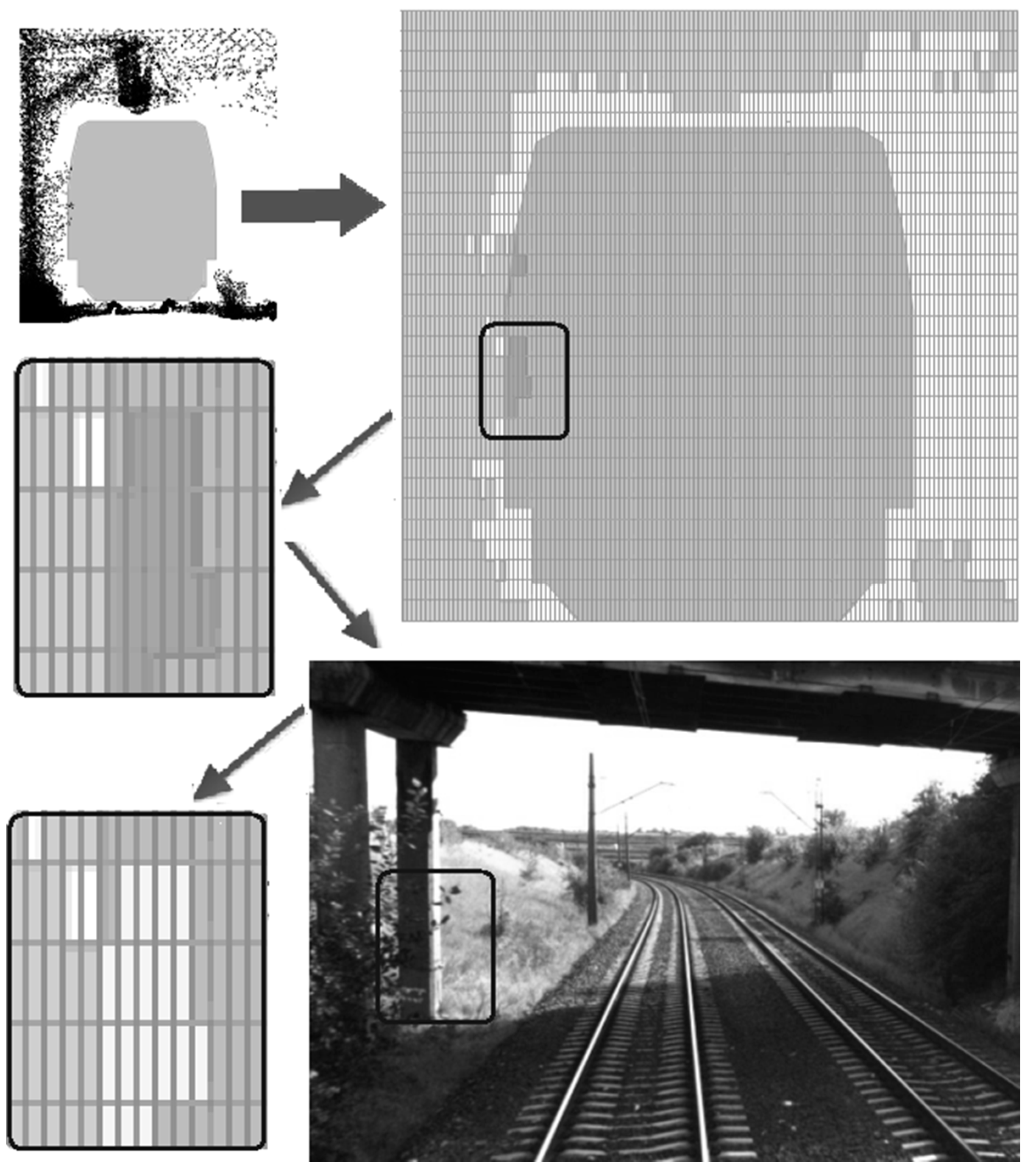
- The database must be capable of importing data directly from measurements, so it must record both point clouds and images. At the same time, data from point clouds is to be analyzed first, while image data is to be used in the event that an area holds some doubts (e.g., areas where the information provided by the point cloud alone is not 100% sufficient to make a decision).
- -
- The database must cooperate with the POS (Leading Network Description) and SILK (Railways Lines Information System) databases. In both of these databases (POS and SILK), the basic way of addressing objects at railway lines is that of chainage. The requirement of the project was the connection of our database with POS and SILK, to exchange the data.
- -
- Due to compatibility with the SILK database, data would be processed under the 1992 national geodetic coordinate system, yet the database must be capable of converting data to other coordinate systems.
- -
- When developing the database, the following input data were utilized:
- -
- GPS/INS data, including the vehicle trajectory coordinates; ca. 200 samples per second.
- -
- Laser scanning data (a point cloud), about 25 million points (~1.5 GB) per kilometer of railway line.
- -
- Images (in JPG format) taken by four cameras; about 350 images (~0.3 GB) per kilometer of railway line.
- -
- Calibration of chainage: Chainage is the basic mode of addressing/indexing railway line objects. Mapping the geographic coordinates to a Linear Referencing System (LRS), which is used in the SILK, can be made with the use of the Oracle Spatial software with dynamic segmentation functions (3D to 1D transformation). The present LRS model for railway lines in the SILK database was made with a cartographic accuracy of 1:25,000 maps. Therefore, a decision was made only to calibrate data based on a dozen or so points obtained from the SILK database.
- -
- Determination of track geometry: Based on GPS data, the examined railway line sections were divided into elementary sections of a length of 1 m each. Assuming that the turning radius is neglectable within such a section, the location of both rails was identified in the point cloud (together with rail height, which made it possible to make allowance for super elevation in further considerations). In this way, the local system of coordinates was determined. Furthermore:
- ○
- the system’s center was precisely positioned vertically just over/on the rails in the Y axis, between the rails in the Z direction and halfway of the section (1 m) along the traveling direction (X) (right-handed system),
- ○
- axis Y was positioned vertically on top of rails and pointing up (making allowance for super elevation),
- ○
- axis X was perpendicular to Y and overlapping the vehicle travel direction,
- ○
- -
- Reduction of data: In order to reduce the amount of 3D data stored in the database, a decision was made to limit the point cloud to strips along the travelling path, being 9.5 m wide (four to the left, four to the right side and 1.5 m as the distance between rails).
- -
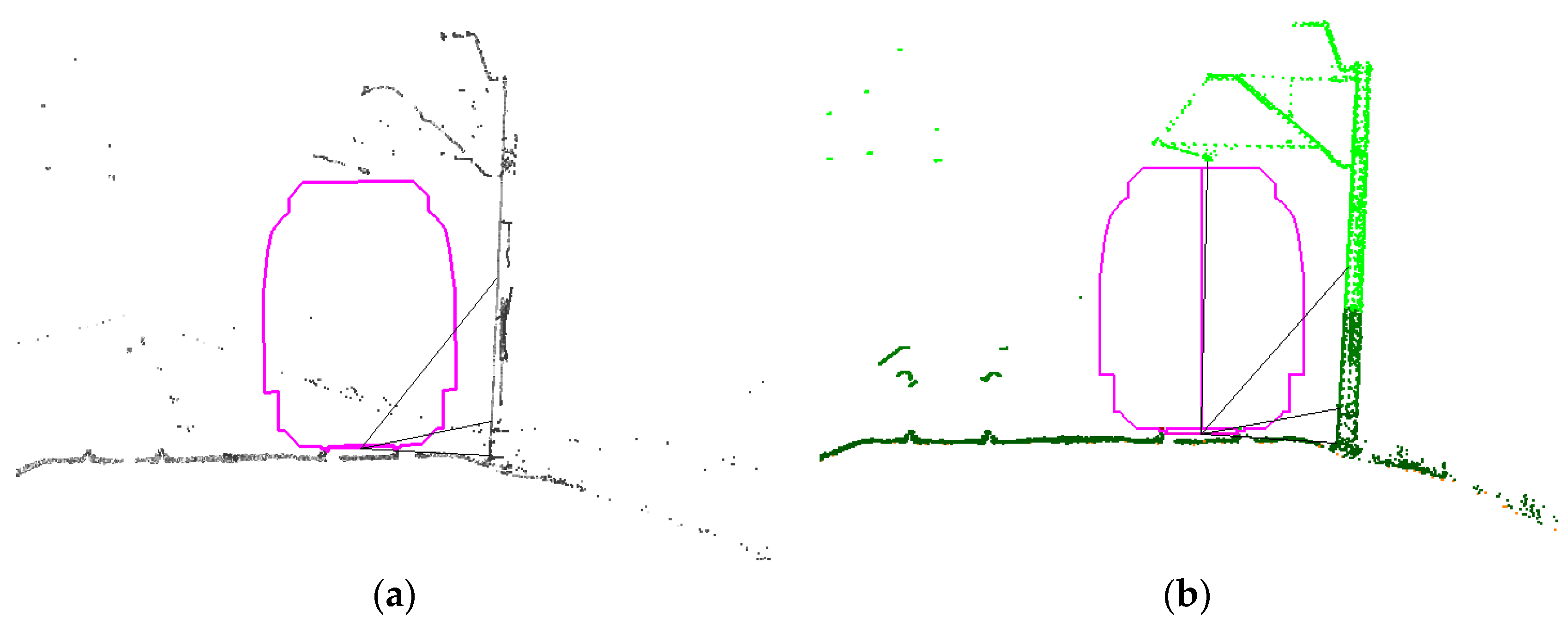
- Considerations regarding the implementation of 2D cross-sections: For each identified 1-m section of the line, a projection of the point cloud upon the YZ plane was made. As each of such sections has its own system of reference, as defined above, and each of those systems is describing space from the viewpoint of a moving vehicle, it is possible to combine such cross-sections. The project participants decided to store in the database cross-sections from 10-m, 100-m and 1-km sections, as well as total cross-sections connected with encoding principles described in the International Union of Railways UIC 502-2 chart and dividing a railway line into segments (i.e., those between railway stations or turnouts).
3.4.1. Conception of Railway Clearance Gauge Determination
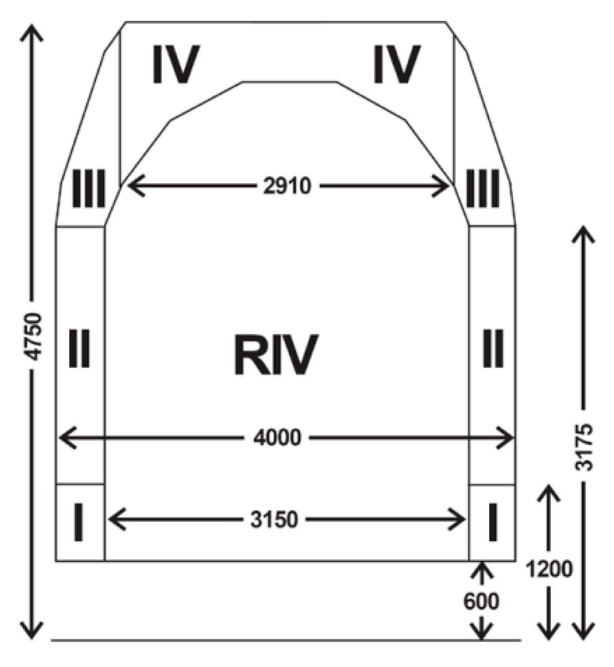
3.4.2. Assigning of Codes
4. Examination of the Selected Mobile Systems in the Application for Measuring the Gauge
4.1. Characteristics of the Tested Measuring Systems
- -
- A system based on a phase scanner profiling in two directions perpendicular to the direction of travel (System 1),
- -
- A system based on two pulse scanners profiling in two directions diagonal to the axis of the track and forward, with integrated cameras (System 2).
4.2. Field Experiments
4.3. The Database Application
- -
- generation of animations
- -
- point cloud visualization
- -
- image viewer
- -
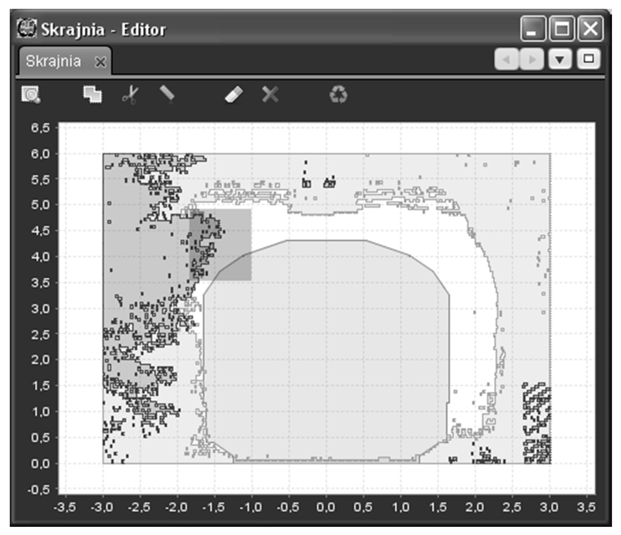
- visualization of 2D cross-sections
- -
- entering the cargo
5. Conclusions
- -
- experiments concerning a point cloud filtration, integration of scanning and photogrammetry and an automatic extraction of edges and special curves,
- -
- research on the current state of play of the knowledge on the effective operation of algorithms of the automatic texturing of railway clearance gauge elements,
- -
- designing a model of a ground-based scanner platform, which was then used in a process of the obtaining and updating of the data necessary for developing a spatial model of railway infrastructure,
- -
- research on the prototype for the database of the railway infrastructure clearance gauge, followed by mathematical analyses necessary in the process of railway codification,
- -
- research for the use of photogrammetric measurements for modelling patterns of the kinematic clearance gauge of cargos,
- -
- developing a methodology for an interactive encoding of a railway line at different variants of cargo transport.
Acknowledgments
Author Contributions
Conflicts of Interest
References
- Mikrut, S.; Mikrut, Z.; Moskal, A.; Pastucha, E. Detection and Recognition of Selected Class Railway Signs. Image Process. Commun. Int. J. 2014, 19, 83–96. [Google Scholar] [CrossRef]
- Briese, C.; Zach, G.; Verhoeven, G.; Ressl, C.; Ullrich, A.; Studnicka, N.; Doneus, M. Analysis of mobile laser scanning data and multi-view image reconstruction. In Proceedings of the International Archives of the Photogrammetry, Remote Sensing and Spatial Information Sciences, Volume XXXIX-B5, XXII ISPRS Congress, Melbourne, Australia, 25 August–1 September 2012.
- Chen, T.; Yamamoto, K.; Chhatkuli, S.; Shimamura, H. Panoramic Epipolar Image Generation for Mobile Mapping System. In Proceedings of the International Archives of the Photogrammetry, Remote Sensing and Spatial Information Sciences, Volume XXXIX-B5, 2012 XXII ISPRS Congress, Melbourne, Australia, 25 August–1 September 2012.
- Kukko, A.; Kaartinen, H.; Hyyppä, J.; Chen, Y. Multiplatform Approach to Mobile Laser Scanning. In Proceedings of the International Archives of the Photogrammetry, Remote Sensing and Spatial Information Sciences, Volume XXXIX-B5, 2012 XXII ISPRS Congress, Melbourne, Australia, 25 August–1 September 2012.
- Zoller+Fröhlich. Available online: http://www.zf-laser.com (accessed on 22 November 2015).
- Blug, A.; Baulig, C.; Dambacher, M.; Wölfelschneider, H.; Höfler, H. Novel platform for terrestrial 3D mapping from fast vehicles. In Proceedings of the International Archives of Photogrammetry, Remote Sensing and Spatial Information Sciences, 36 (3/W49B), PIA07 Photogrammetric Image Analysis ISPRS Technical Commission III Symposium, Munich, Germany, 19–21 September 2007.
- Schewe, H.; Holl, J.; Gründig, L. LIMEZ—Photogrammetric Measurement of Railroad Clearance Obstacles. Available online: http://www.technet-gmbh.de/fileadmin/Photogrammetrie/Publikationen/Limez-english.pdf (accessed on 11 May 2016).
- L-KOPIA. Available online: http://www.lko.se (accessed on 22 November 2015).
- Street Mapper. Available online: http://www.igi.eu/streetmapper.html (accessed on 22 November 2015).
- Topcon IP-S2. Available online: http://www.topcon.co.jp/en/positioning/products/product/3dscanner/IP-S2_Lite_E.html (accessed on 22 November 2015).
- Jongeleen, S.; Evans, A.; Digue, M. Mobile Mapping in a Southern African Context. Available online: http://ee.co.za/wp-content/uploads/legacy/PostionIT%202011/visualisation_july%202011_%20mobile-mapping-1.pdf (accessed on 11 May 2016).
- Kukko, A.; Kaartinen, A.; Hyyppä, J.; Chen, Y. Multiplatform Mobile Laser Scanning: Usability and Performance. Sensors 2012, 12, 11712–11733. [Google Scholar] [CrossRef]
- Lin, Y.; Hyyppä, J.; Kaartinen, H.; Kukko, A. Performance analysis of mobile laser scanning systems in target representation. Remote Sens. 2013, 5, 3140–3155. [Google Scholar] [CrossRef]
- Kaartinen, H.; Hyyppä, J.; Kukko, A.; Jaakkola, A.; Hyyppä, H. Benchmarking the performance of mobile laser scanning systems using a permanent test field. Sensors 2012, 12, 12814–12835. [Google Scholar] [CrossRef]
- Trible. Available online: http://www.trimble.com/Imaging/Trimble-MX8.aspx (accessed on 22 November 2015).
- GPSVision. Available online: http://www.lambdatech.com/GPSVOverview.html (accessed on 22 November 2015).
- GeoAutomation. Available online: http://www.geoautomation.com/technology.html (accessed on 22 November 2015).
- GeoVISAT. Available online: http://www.vansteelandt.be/geovisat/menu031.html (accessed on 22 November 2015).
- OmniVision. Available online: http://omnicomengineering.co.uk/wp-content/uploads/2014/11/OMNIVISION.pdf (accessed on 22 November 2015).
- Earthmine-Mars Collection System. Available online: http://www.earthmine.com/html/products_mobile.html (accessed on 22 November 2015).
- Chen, Z.; Hu, Q.; Guo, S.; Yuan, J. Application of L-MMS in Railroad Clearance Detection. In Proceedings of the 5th International Symposium on Mobile Mapping Technology, Padua, Italy, 29–31 May 2007.
- Talaya, J.; Bosch, E.; Alamus, R.; Serra, A.; Baron, A. Geovan: The Mobile Mapping System from the ICC. In Proceedings of the 4th International symposium on Mobile Mapping Technology, Commission VI, WG VI/4, Kunming, China, 29–31 March 2004.
- Balfour Beatty Rail Technologies. Available online: http://www.balfourbeatty.com/media/29280/laserflex-brochure.pdf (accessed on 22 November 2015).
- Zhan, D.; Yu, L.; Xiao, J.; Chen, T. Multi-Camera and Structured-Light Vision System (MSVS) for Dynamic High-Accuracy 3D Measurements of Railway Tunnels. Sensors 2015, 15, 8664–8684. [Google Scholar] [CrossRef] [PubMed]
- Clipp, B.; Raguram, R.; Frahm, J.; Welch, G.; Pollefeys, M. A Mobile 3D City Reconstruction System. In Proceedings of the IEEE Virtual Reality 2008 Workshop on Cityscapes, Reno, NV, USA, 2008.
- Früh, C.; Zakhor, A. An Automated Method for Large-Scale, Ground-Based City Model Acquisition. Int. J. Comp. Vis. 2004, 60, 5–24. [Google Scholar] [CrossRef]
- Frueh, C.; Jain, S.; Zakhor, A. Data Processing Algorithms for Generating Textured 3D Building Façade Meshes from Laser Scans and Camera Images. Int. J. Comp. Vis. 2005, 61, 159–184. [Google Scholar] [CrossRef]
- Frueh, C. Automated 3D Model Generation for Urban Environments. Ph.D. Thesis, University of Karlsruhe, Karlsruhe, German, 20 September 2003. [Google Scholar]
- Kremer, J.; Grim, A. The Railmapper—A Dedicated Mobile Lidar Mapping System For Railway Networks. In Proceedings of the International Archives of the Photogrammetry, Remote Sensing and Spatial Information Sciences, Volume XXXIX-B5, 2012 XXII ISPRS Congress, Melbourne, Australia, 25 August–1 September 2012.
- Kohut, P.; Mikrut, S.; Pyka, S.; Tokarczyk, R.; Uhl, T. Research on the prototype of rail clearance measurement system. In Proceedings of the Volume XXXIX-B4, 2012 XXII ISPRS Congress, Melbourne, Australia, 25 August–1 September 2012; pp. 385–389.
- Warda, A.; Leszczewicz, Z.; Barszcz, T.; Kohut, P.; Mikrut, S.; Przywieczerski, J.; Pyka, K.; Sitkowski, T.; Tokarczyk, R.; Uhl, T. The Use of MLS for Measuring Railway Clearance Gauge and Constructing Railway Lines Codification System. In Proceedings of the Infraszyn 2013 6th Scientific and Technological Conference on Infrastructure Designing, Constructing and Maintenance in Railway Transport, Zakopane, Poland, 24–26 April 2013. (In Polish)


| Rail Line Code | 3 | 3 | 5 | 4 | 4 | 465 |
| Cargo Code | 0 | 0 | 4 | 4 | 4 | 425 |
| Results | OK | OK | OK | OK | OK | Ok |
| Rail Line Code | 3 | 3 | 5 | 4 | 4 | 465 |
| Cargo Code | 0 | 0 | 4 | 6 | 6 | 425 |
| Results | OK | OK | OK | Not | Not | Not |
| Standard Deviation | Arithmetic Mean | |||
|---|---|---|---|---|
| dx (m) | dy (m) | dx (m) | dy (m) | |
| Track 1 | 0.021 | 0.024 | 0.004 | −0.002 |
| Track 2 | 0.008 | 0.016 | 0.002 | −0.005 |
| Standard Deviation | Arithmetic Mean | |||
|---|---|---|---|---|
| dx (m) | dy (m) | dx (m) | dy (m) | |
| Track 1 | 0.017 | 0.026 | 0.004 | −0.005 |
| Track 2 | 0.014 | 0.023 | −0.002 | −0.001 |
| Standard Deviation | Arithmetic Mean | |||
|---|---|---|---|---|
| dxy (m) | dz (m) | dxy (m) | dz (m) | |
| Track 1 | 0.006 | 0.005 | 0.019 | 0.010 |
| Track 2 | 0.005 | 0.002 | 0.025 | 0.008 |
| dxy (m) | dz (m) | |
|---|---|---|
| Standard Deviation | 0.021 | 0.006 |
| Arithmetic Mean | 0.019 | 0.025 |
© 2016 by the authors; licensee MDPI, Basel, Switzerland. This article is an open access article distributed under the terms and conditions of the Creative Commons Attribution (CC-BY) license (http://creativecommons.org/licenses/by/4.0/).
Share and Cite
Mikrut, S.; Kohut, P.; Pyka, K.; Tokarczyk, R.; Barszcz, T.; Uhl, T. Mobile Laser Scanning Systems for Measuring the Clearance Gauge of Railways: State of Play, Testing and Outlook. Sensors 2016, 16, 683. https://doi.org/10.3390/s16050683
Mikrut S, Kohut P, Pyka K, Tokarczyk R, Barszcz T, Uhl T. Mobile Laser Scanning Systems for Measuring the Clearance Gauge of Railways: State of Play, Testing and Outlook. Sensors. 2016; 16(5):683. https://doi.org/10.3390/s16050683
Chicago/Turabian StyleMikrut, Sławomir, Piotr Kohut, Krystian Pyka, Regina Tokarczyk, Tomasz Barszcz, and Tadeusz Uhl. 2016. "Mobile Laser Scanning Systems for Measuring the Clearance Gauge of Railways: State of Play, Testing and Outlook" Sensors 16, no. 5: 683. https://doi.org/10.3390/s16050683
APA StyleMikrut, S., Kohut, P., Pyka, K., Tokarczyk, R., Barszcz, T., & Uhl, T. (2016). Mobile Laser Scanning Systems for Measuring the Clearance Gauge of Railways: State of Play, Testing and Outlook. Sensors, 16(5), 683. https://doi.org/10.3390/s16050683


