1. Introduction
Wireless power-transmission systems based on inductive coupling are extensively used in implantable microelectronic devices to increase patient’s comfort and reduce the risk of infection due to the use of transcutaneous wires or the chemical side effects of a battery. The size and lifetime of the battery is another issue of concern in powering bio-implantable devices. The smallest possible size is a major requirement for bio-implants. Depending on its size, the functional depth of an implantable device in a human biological tissue is determined. Usually, these devices are placed in less than 10 mm of depth in human tissue. General implanted microsystems are placed at 1–4 mm of depth. Cochlear implants need to be placed at 3–6 mm inside the temporal bone, and for retinal implants, the expected depth is 5 mm [
1,
2,
3].
The applications of wireless power transmission span over a broad range from submicrowatt to few kilowatts [
4,
5,
6,
7,
8,
9,
10,
11,
12]. Inductive-coupling-based wireless power transfer (WPT) systems are commonly used for implantable devices [
13,
14,
15,
16,
17,
18]. The primary and secondary coils are used as the transmitter (TX) and receiver (RX), respectively, in a two-coil-based inductively coupled WPT. A two-coil-based WPT system suffers from low quality factor (Q-factor or Q) and low coupling coefficient (
k) due to the source and load resistances. Hence, the maximum achievable power-transfer efficiency (PTE) is relatively low in such systems [
19,
20,
21]. Moreover, most of the previous coils are designed based on filament or Litz wire. The manufacturing and reduction of the size of such coils require proper expertise and sophisticated machinery. As a result, planar and lithographically defined printed spiral coils (PSCs) were introduced in [
22]. Flexibility and geometric compactness make the PSC suitable for biomedical devices.
The PTE of a WPT system depends on the architecture (dimension and structure) of the coils, physical spacing between the coils, relative location, and environment of the coils. The mutual spacing between the TX (or external coil) and RX (or implanted coil) of a biomedical implant must be smaller than the wavelength in the near field and it depends on the dimensions of the coils. The implanted coil must be carefully designed as it is located inside the human body, and it should be as small as possible.
An efficient power-transfer method is required for bio-implants to satisfy the power specification and safety issues. Thus, resonant-based power delivery technique has become popular nowadays. This WPT technique typically uses four coils (source, primary, secondary, and load) [
23]. The source and primary coils as well as the secondary and load coils are coupled by inductive link. In the TX side, a pair of coils, which are referred to as the source (coil 1 or C1) and primary (coil 2 or C2) coils is used, shown in
Figure 1. Another pair of coils, which are referred to as the secondary (coil 3 or C3) and load (coil 4 or C4) coils is used on the RX side. All the coils are tuned at the same resonance frequency (
fres) by
C1–
C4 capacitors.
R1–
R4 are parasitic resistances.
Li, where
i = 1 to 4, is the self-inductance of the coil.
Mij and
kc.ij represent the mutual inductance and coupling coefficient, respectively, of two adjacent coils. In four-coil-based WPT, the TX coil stores energy in the same way as a discrete LC tank. TX coil can be modeled as a tuned step-up transformer as well, where the source can be represented as a primary of the transformer and it can be connected to the source through a power amplifier. The primary of the TX coil can be modeled as the secondary of the transformer which is left open. The RX functions in a similar manner as a step-down transformer. In contrast with the two-coil-based WPT, the effect of source and load resistance can be reduced by the C1 and C4, respectively, in a four-coil WPT, thus can enhance the overall PTE. In a four-coil-based WPT, a high matching condition can be achieved by adjusting the coupling coefficient between source-primary and secondary-load coils. Therefore, it is possible to transfer high power to the load. The distance between TX and RX is 10–20 mm, and the separation medium is human biological tissue. The architecture of the TX and RX coils shown in
Figure 1 is conformal [
24,
25,
26] or fully planar [
27]. This structure eliminates the possibility of misalignment between coil 1 and coil 2 as well as between coil 3 and coil 4 [
28]. Thus, this method improves the overall PTE under misalignment conditions.
In this paper, a fully planar four-coil magnetic resonance coupling (MRC)-based WPT is analyzed using circuit-based modeling. Both square and circular architectures are considered for analysis and optimization for asymmetrical spiral inductors. The reflected-load theory [
29] is used to analyze the Q-factor and power delivered to the load (PDL). The accuracy of the design model is improved by considering the effects of parasitic components as well as the surrounding environments. Critical design parameters, including the TX and RX dimensions, number of turns of the PSC, self- and mutual inductances, coupling coefficients, and Q-factors, are analytically investigated, and the optimum design is determined by applying the design constraints through a step-by-step procedure in MATLAB. A simulation-based comparative study is done on the PTE of the MRC-WPT of both square and circular resonators in air and the human-tissue media. Effect of misalignment on over-all PTE is characterized and measured as well.
This paper is organized as follows:
Section 2 formulates the theoretical modeling of the MRC-WPT system.
Section 3 describes the optimization method of the PSCs using an iterative approach by utilizing the theoretical model of
Section 2 in MATLAB.
Section 4 presents the simulation results, experimental setup, and necessary comparisons of the results.
2. Theoretical Modeling of MRC-WPT System
This section illustrates the individual models for the self- and mutual inductance, parasitic components, and Q-factor. The models are based on both square and circular coils in the PSC architecture. A detailed analysis of the PTE and PDL is presented on the basis of the accurate equivalent circuit model of the proposed MRC-WPT system.
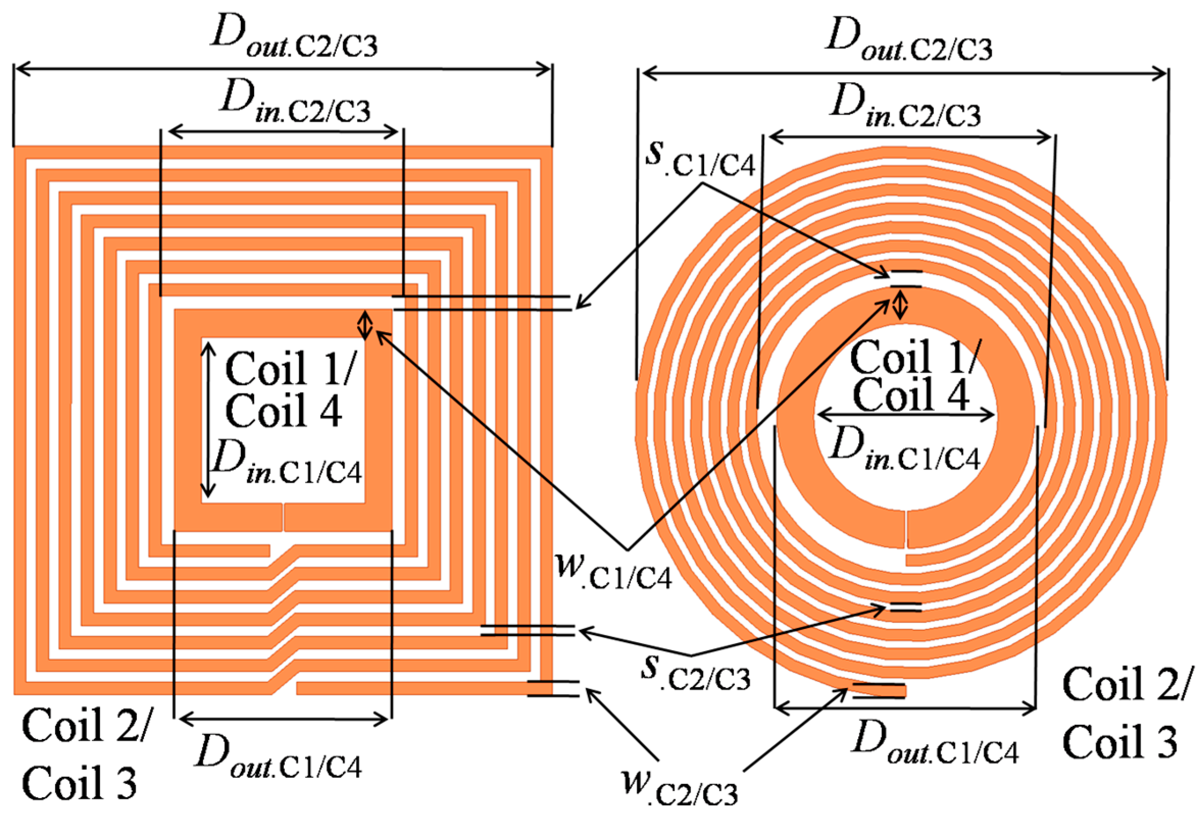
Figure 2 shows the proposed planar MRC-WPT architecture and the geometrical parameters of both the square- and circular-shaped coils. In
Figure 2, coil 1 or coil 4 represents the source or load coil, respectively, and coil 2 or coil 3 represent the primary or secondary coil, respectively.
Din.Cx/y and
Dout.Cx/y denote the inner and outer diameters, respectively. In addition, another two important parameters
w.Cx/y and
s.Cx/y represent the line width and spacing, respectively. The subscript “C
x/y” corresponds to a particular coil from C1 to C4.
2.1. Inductance Modeling
Self-inductance
L is a function of the magnetic flux of the current-carrying conductor and the amount of current flowing through the conductor. The sides of the spirals are approximated to be symmetrical current sheets to measure the self-inductance. Adjacent sheets are considered as orthogonal with zero mutual inductance. On the other hand, the current-carrying opposite sheets have mutual inductance
M. Equation (1) expresses the simplified self-inductance, which is estimated using the concept of geometric mean, arithmetic mean, and arithmetic mean square distances [
30]:
where
ϕ = (Dout.Cx −
Din.Cx)/(Dout.Cx + Din.Cx), which is the fill factor, and
Cli is the layout-dependent coefficient. For circular coils,
Cl1 = 1,
Cl2 = 2.46,
Cl3 = 0.0, and
Cl4 = 0.2. For square coils,
Cl1 = 1.27,
Cl2 = 2.07,
Cl3 = 0.18, and
Cl4 = 0.13. In Equation (1),
n.Cx represents the number of PSC turns of coil C
x (where
x = 1, 2, 3, and 4).
For unity-turn coils, the Neumann’s equation to calculate the mutual inductance between two current-carrying filaments can be simplified as Equation (2) [
31]:
where
ai =
Dout.Cx−(
n.Cxi1)(
w.Cx+
s.Cx) −
w.Cx/2,
bj =
Dout.Cy− (
n.Cyj− 1)(
w.Cy +
s.Cy) −
w.Cy/2,
γij = 2
aibj/(
ai2 +
bj2+
d2) and
d is the distance between two adjacent coils. Parameter
ρ [
31] is a structure-dependent term.
Equation (2) estimates all possible Ms among the planar inductors by considering each turn, and the total M can be determined by adding all the combinations. If both TX and RX are circular shaped, ρ = 1. Otherwise, for square-shaped TX and RX coils, ρ can be approximated as (4/π)2. Thus, the M value between two square-shaped coils is (4/π)2 times greater than that of the circular-shaped coils.
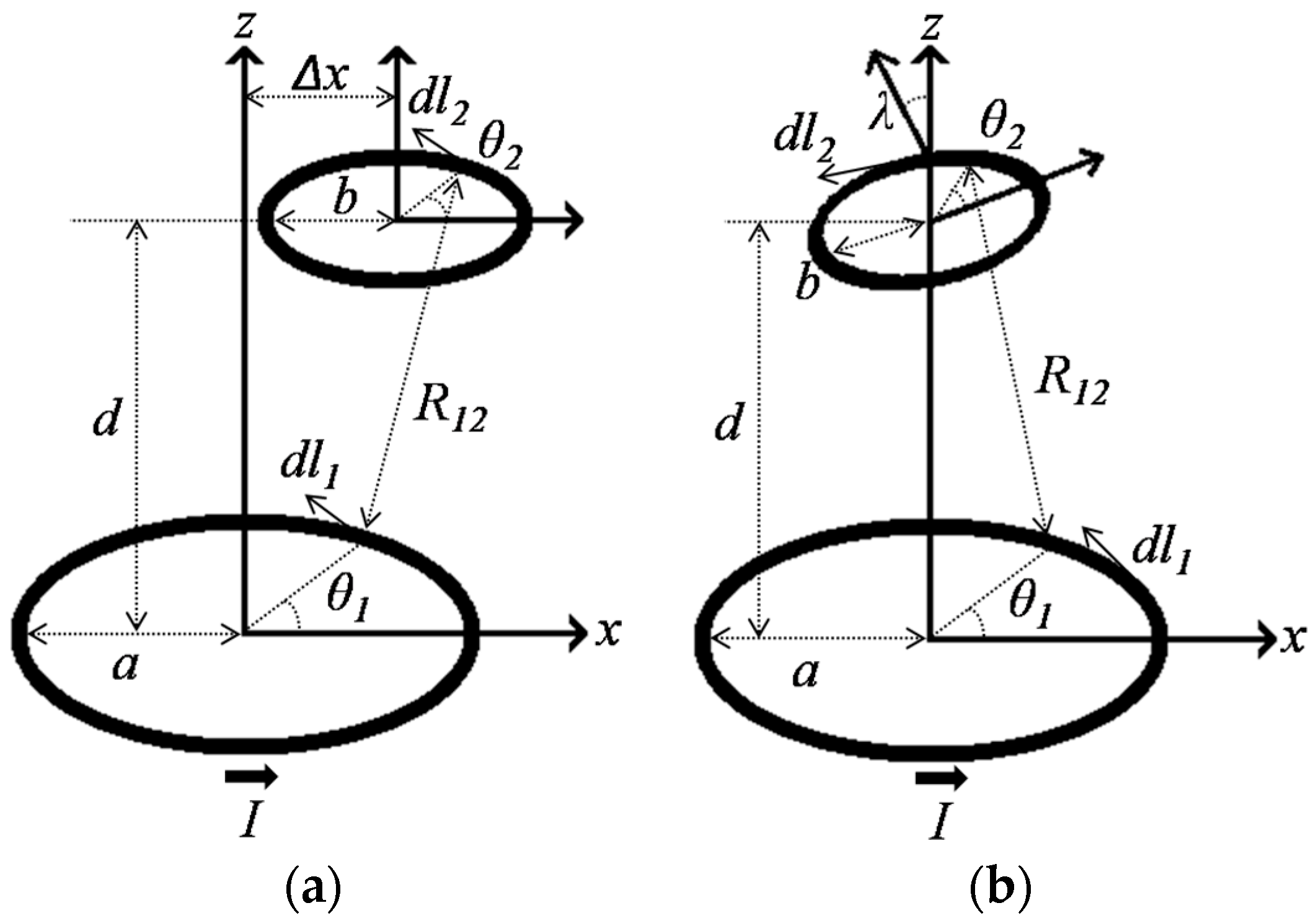
Figure 3a shows the configuration of the planar coils for lateral misalignment. Δ
x represents the lateral displacement.
The distance between two arbitrary points on those coils is assumed as:
M is expressed by using three new parameters [
31], where
γ = 2
ab/(
a2 +
b2+
d2+Δ
x2),
α = 2Δ
xa/(
a2 +
b2+
d2+Δ
x2), and
β = 2Δ
xb/(
a2 +
b2+
d2+Δ
x2). Thus:
For simplification, the [1 − (
γcos(
θ1−
θ2) +
αcos
θ1−
βcos
θ2)]
−1/2 term in Equation (3) can be expanded by Taylor series and solved as:
where
σ = Δ
x2/(
a2 +
b2+
d2+Δ
x2).
Figure 3b shows the configuration of angular misalignment and it is represented by
λ. The distance between two arbitrary points on those coils is evaluated by:
By introducing the parameter
γ = 2
abcos
λ/(
a2 +
b2+
d2) and
α = 2
bdsin
λ/(
a2 +
b2+
d2),
M can be expressed as follows:
M can be further simplified by Taylor series from Equation (5) to:
To realize a complete planarization of the system, C1 and C2 (as well as C3 and C4) are printed on the same side of the substrate. Therefore, the distance becomes zero between the C1 and C2 coils, along with the C3 and C4 coils. In such condition, Equation (2) reveals a large error in calculating
M12 and
M34. Hence, it can be expanded as Equation (7) [
27]:
2.2. Parasitic Capacitance
Parasitic capacitance,
Cpr is a function of the spacing between planar conductive traces and the materials present at the surrounding of the PSCs. High permittivity of the tissue can also increase the parasitic capacitance of the implanted PSC [
21].
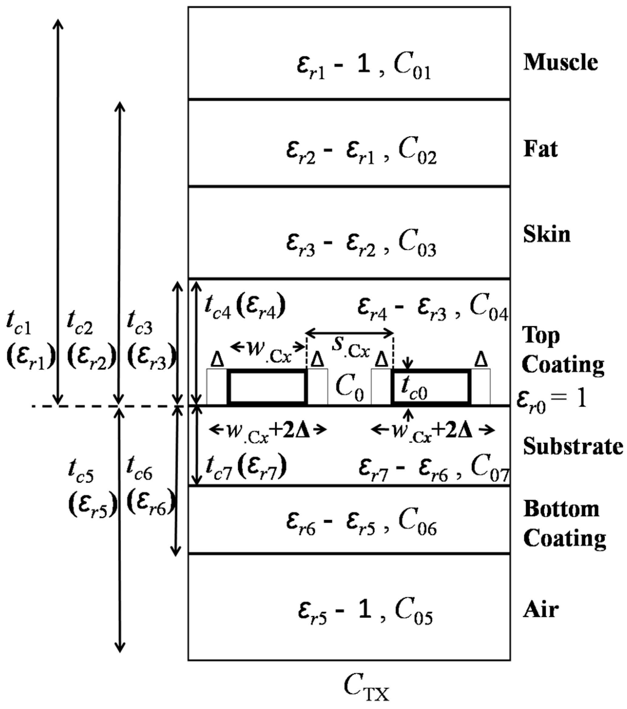
Figure 4 shows a modeled unit-length parasitic capacitance of a TX coil.
The PSC is considered as a coplanar stripline sandwiched between multiple dielectric layers. The metal traces of the PSC are printed on a substrate. The top and bottom sides of the substrate are insulated with coating layers. One side of the PSC is human tissue and the other side is air. To realize a more realistic human tissue model, three layers of biological tissues are considered to enhance the approximation accuracy. The general architecture of the biological tissue is formed using consecutive layers of skin, fat and muscle. Moreover, for the RX or implanted coil the air should be replaced by the biological tissue, depending on the anatomical location of the coil. In
Figure 4,
tci,
ɛri,
CTX,
C0, and
C0i represent the layer thickness, relative dielectric constant, total capacitance per-unit length of the TX PSC, free-space capacitance of the adjacent traces, and partial capacitance of the dielectric layer, respectively, where,
i = 0 to 7. According to [
32], PSC metal thickness
tc0 affects the overall
CTX, and it can be utilized by adjusting the PCS line width and spacing by 2Δ, where:
εa represents the mean value of the permittivity of the layers in contact with the PSC strips, and weff is the effective width of the PCS metal traces.
An accurate method to approximate
CTX is presented in [
33]. Based on conformal mapping and superposition of the partial capacitances,
CTX can be simplified as:
where
εeff is the effective relative dielectric constant.
Theoretically,
C0 can be calculated using Schwartz transformation and can be represented as:
where
K is the complete elliptical integral of the first kind and
K’ (
ki) =
K(
ki’).
ki and
ki’ can be expressed as:
The ratio of
K(
ki)/
K’(
ki) in Equation (13) can be further simplified using the Hilberg approximation and can be expressed as:
To communicate with the inner terminal, a conductor bridge has to be built. This bridge or via goes across all other turns of the PSC and results in additional parasitic capacitance, which is known as overlapping trace capacitance or
Ctov, where:
Here,
Atov is the overlapping area, and
ttov (≈
tc7) is the spacing between the two metal layers. The effective dielectric constant
ɛeff_ov between two conductive plates can be found in [
34]:
Finally, the total parasitic capacitance of the TX PSC can be calculated by:
where
lc is the length of the conductive trace of the PSC for square coil Equation (18a) [
22] and circular coil Equation (18b), respectively:
2.3. AC Resistance
The Q-factor of the inductor is a function of the effective series resistance (ESR). Thus, to achieve a high Q-factor, the ESR of the inductor coil must be as low as possible. At high frequencies, the skin effect can severely increase. Series resistance
Rs is dominated by dc resistance
Rdc of the PSC conductive trace:
where
ρc represents the resistivity of the PSC conductive material. Skin-effect resistance
Rskin can be calculated using Equation (19). Therefore:
where
δ is the skin depth,
µ0 is the permeability of free space,
µr is the relative permeability of the metal layer, and
f is the operating frequency.
Eddy current is another source of parasitic resistance. The magnetic fields of the external PSC and the adjacent turns of the same PSC can cause eddy current generation. The direction of the eddy currents is opposite that of the main current flow, thus, it increases the PSC effective resistance. The modified resistance by adding the effect of eddy currents [
21] can be expressed as:
where
Rsheet is the metal trace sheet resistance. Consequently, final
Rs can be represented as:
2.4. Q-Factor
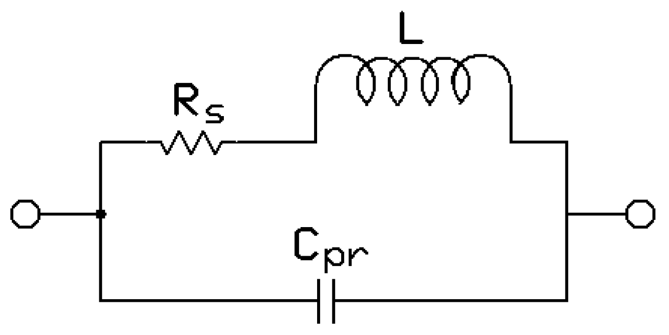
Figure 5 shows the lumped model of the resonator coil.
Considering that
Rs is in series with
L and
Cpr is parallel with both
Rs and
L, the overall impedance of a coil can be expressed as [
23]:
The effective self-inductance
Leff and ESR can be modeled as:
The ESR significantly increases as the operating frequency of the coil approaches
fres. For a frequency higher than
fres, the coil behaves as a capacitor, and hence, it cannot be used as an inductor. The Q-factor of an unloaded inductor can be:
2.5. Power Transfer Efficiency
By applying the circuit theory to
Figure 6, the relationship between the current through each coil and the voltage applied to the source can be expressed in the following matrix form [
23]:
Equation (28) can be further expanded as [
35,
36,
37]:
where
Rsrc is the source resistance and
Rload is the load resistance.
Rsrc and
R4 are small in magnitude, and at resonant frequency,
jωL = 1/
jωC. Hence, the imaginary part of the corresponding element is zero. C1 and C4 are small in size; thus, they have a very small inductance and can be neglected. The large distances between C1 and C4, C1 and C3, and C2 and C4 result insignificant mutual inductance and mutual resistance [
23,
35,
38]. Therefore a simplified form of Equation (29) can be expressed as:
To simplify PTE equation,
Mij is usually normalized by using
Li and
Lj by defining
kc.ij as:
At resonance, PTE
η can be expressed as:
For loaded Q-factor
Q4L, Equation (32) can be expanded as [
39]:
where
QL (=
Rload/
ωL4) is the load Q-factor and
Q4L = (
Q4·
QL)/(
Q4 +
QL). The PTE (
η23) of loosely coupled C2 and C3 is the dominant factor in determining the overall PTE of the four-coil link at large coupling distance
d. In Equation (27), the effects of adjacent coils in a multi-coil-based system are ignored. In contrast, Q-factor can be estimated more accurately by considering the effect of reflected impedance from the load coil back to the driver coil, one stage at time in a multi-coil system. At resonance, the effect of RX on TX can be modeled using the reflected impedance [
40]:
In Equation (34),
Rref.j,j+1 represents the reflected load from (
j + 1)th to
jth coil, where
kc.j,j+1 is the coupling coefficient between the
jth and (
j + 1)th coils and all coils are tuned at
fres.
Q(j+1)L is the loaded Q-factor of the (
j + 1)th coil, which can be obtained from:
where,
Qj =
Qunloaded = (ω
Lj/
Rj) and
Rj are the unloaded quality factor Equation (27) and parasitic series resistance of the
jth coil, respectively. According to Equation (34), when
RLoad is reflected onto C3 through C4, it limits the Q-factor of C3 [
40]. Similarly, the total impedance in the secondary coil (C3) is reflected onto the primary coil (C2) and reduces the Q-factor of C2 (
Q2 =
ωL2/
R2), which can be expressed as:
From Equation (36) it can be inferred that strong coupling between C2 and C3 (i.e., high
kc.23) reduces
Q2L and thus,
η12, which is the PTE between C1 and C2. In Equation (36)
Q2L is roughly proportional to
kc.23−2, where
kc.23 is further inversely proportional to
d2 [
23]. Therefore,
Q2L is proportional to
d4. For a small
d,
Q2L will reduce significantly. It implies that
η12 will reduce enormously as well.
η12 can be expressed as [
40]:
In Equation (37),
η12 is significantly reduced at small
d if
kc.12 is not chosen to be large. According to Equation (34), large
kc.12 results in a large reflected load on C1, which can reduce the available power from the source. On the other hand, PDL
Pload can be calculated by multiplying the power provided by power source
E by the PTE as [
40]:
4. Fabrication and Results
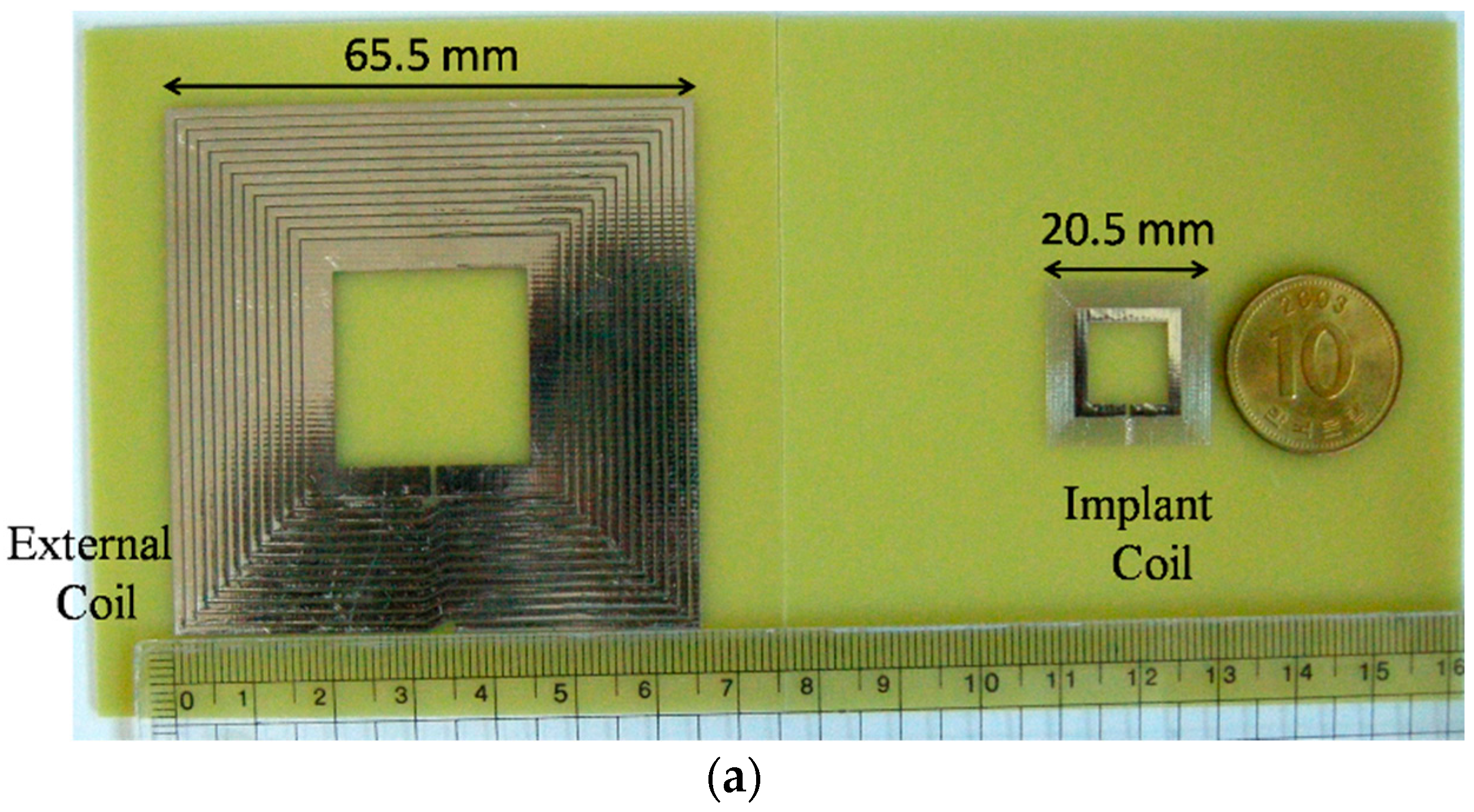
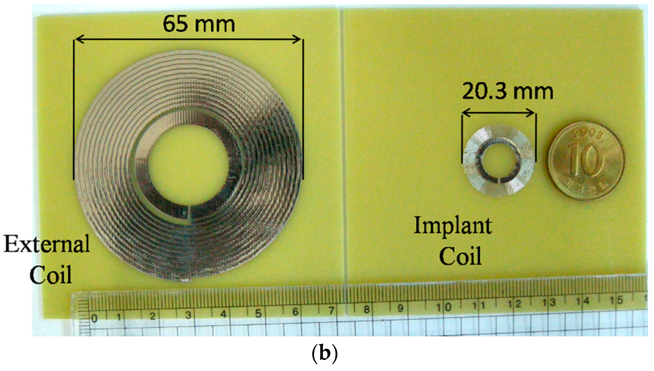
To verify the accuracy of the PTE and PDL equations through measurement, both the square and circular fully planar four-coil MRC-WPTs are fabricated on 1.6-mm-thick FR4 printed circuit boards.
Figure 13a,b shows the fabricated square and circular coils, respectively. For a nominal coupling distance of
d = 10 mm,
Rload = 100 Ω, and
f = 13.56 MHz,
Table 4 lists the electrical specifications of the designed coils achieved from simulation.
Figure 14 shows the experimental setup [
35] to verify the fabricated coils. Resonant circuit similar to
Figure 6 is built for both the square and circular coils. A signal generator is used as a power source and
Rsrc = 50 Ω. For the measurement, an oscilloscope (DPO 4034, Tektronics, Beaverton, OR, USA) and an LCR meter are used. The transmitted and received power can be easily determined by measuring the current and voltage waveforms.
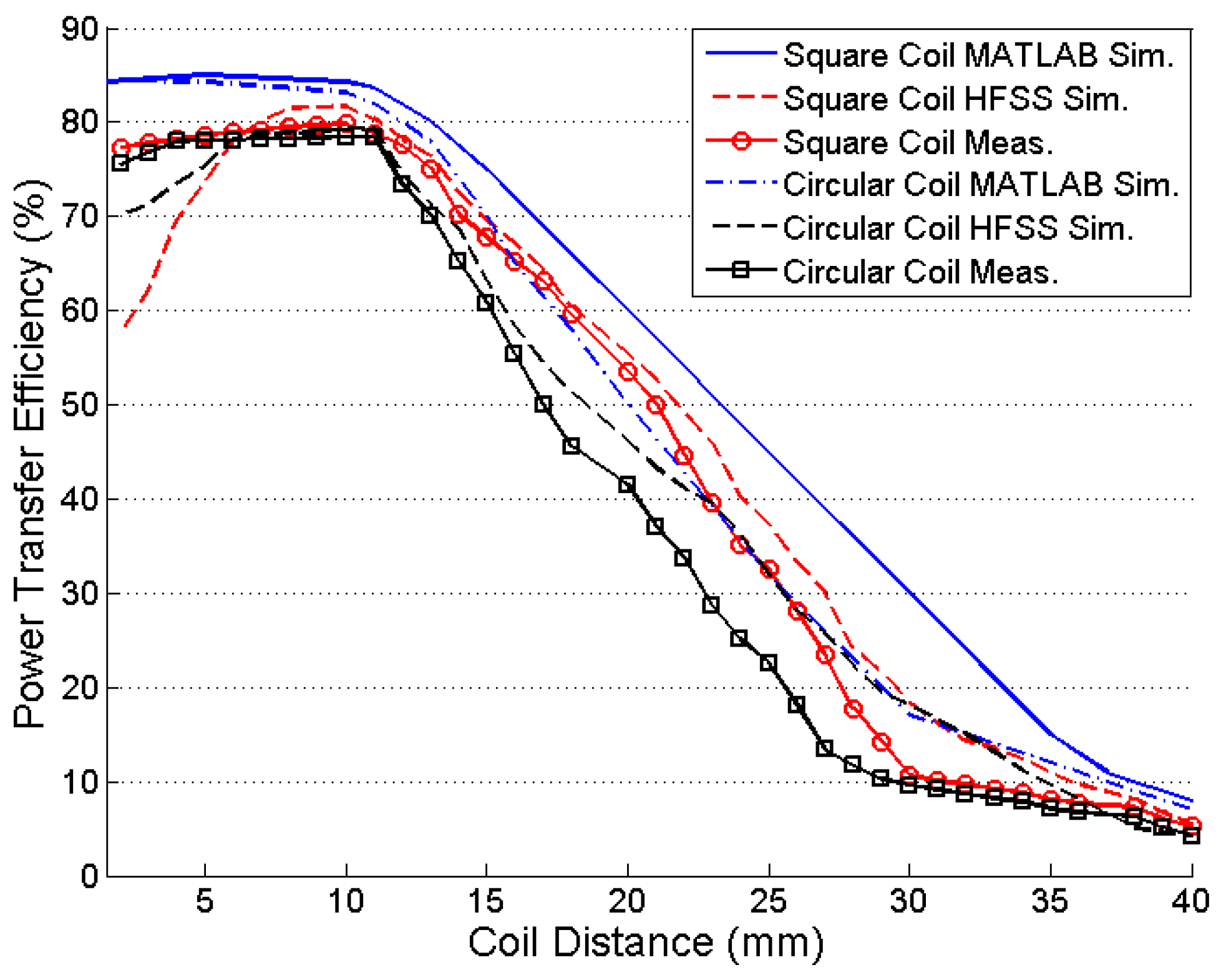
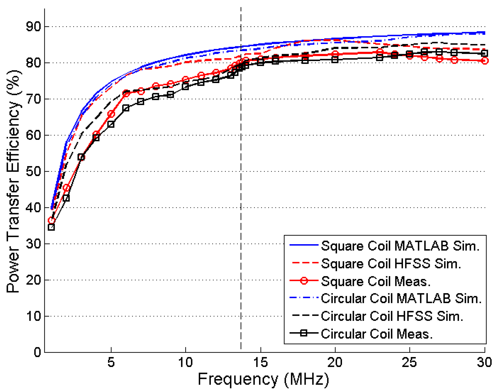
Figure 15 shows the comparison of the calculated, simulated, and measured values of the PTE versus coupling distance in the square and circular coil inductive links. The designed coils are optimized for 10 mm of coupling distance and generate a maximum PTE at that specified coupling distance. High
Rsrc is an important factor to degrade the PTE performance from the MATLAB simulation to HFSS simulation and measurement data. During MATLAB simulation of PTE in Equation (33) the effect of
kc.14,
kc.24, and
kc.13 are neglected. At
d < 5 mm, these parameters cannot be neglected. The effect of
Rsrc in Equation (30) is not considered as well for the simplicity of the calculation and simulation in MATLAB. Thus, there is a discrepancy visible between the calculation (MATLAB simulation) and measured data (HFSS simulation and measured) at
d < 5 mm.
For a frequency sweep of 500 Hz to 30 MHz, the PTE is maximized at approximately 13–14 MHz because of the high Q-factor of the PSCs for both the square and circular coils, as shown in
Figure 16. The improvement in PTE is very small at higher frequencies.
Figure 17 shows the effect of lateral misalignment on PTE. The variation of PTE for Equation (4) is simulated using MATLAB and verified by HFSS simulation and measurement. TX coil is kept constant and RX coil’s positions are changed from 0 mm to 20 mm lateral plane for both simulation and experimental measurement at
d = 10 mm. The PTE decreases significantly for higher lateral displacement of the RX coil. The effect of angular misalignment on PTE is observed for MATLAB simulation, HFSS simulation, and practical measurement on
Figure 18. For
d = 20 mm the PTE is simulated and measured for
λ = 0 to 13 degree. The PTE decreases exponentially in both the cases of lateral and angular misalignments.
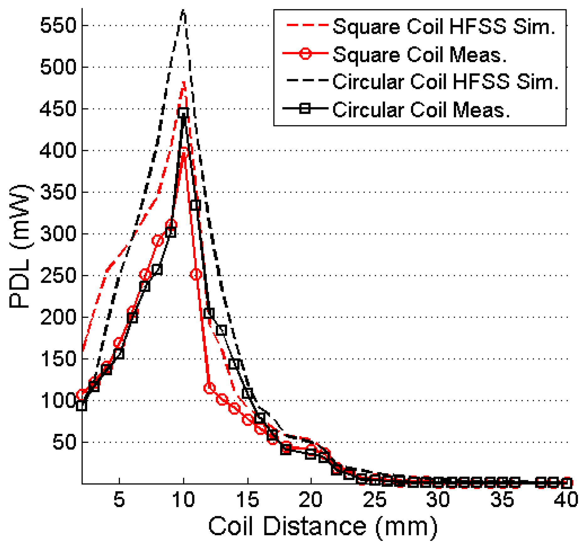
The output power at a 100-Ω load resistance of the system is simulated and measured, and its plot is shown in
Figure 19. For 10 mm of coupling distance between the TX and RX coils and 13.56-MHz frequency, the maximum simulated and measured PDLs for the square coil resonator are 481.76 and 396 mW, respectively.
Table 4 lists the comparison of the coupling coefficients between the square and circular coils. Thus, Equation (37) justifies the higher PDLs of the circular coil, which are 570.35 and 443.5 mW, respectively, under the simulation and measurement conditions.
Figure 20 shows the effect of changing load on the received power. The PDL is reduced significantly for a 10 K-Ω load resistor. The minimum simulated and measured received power is 14.6 mW and 11.7 mW, respectively, for the square coil resonator for 10 K-Ω load resistor. In case of circular coil, simulated and measured PDLs are 11.85 mW and 12.85 mW, respectively, for a 10 K-Ω load.
Table 5 lists the summary and comparison of the work presented in this paper with previous works. The comparison is focused only on the four-coil based resonators for different applications where the coupling medium and surrounding environment is air. Both the square and circular coils are also simulated in a biological tissue medium. In contrast to the air medium, the PTE significantly degrades in the tissue medium. In HFSS, the 10-mm tissue medium is created similar to that shown in
Figure 1, where we consider that the skin, fat, and muscle-tissue thicknesses are 1, 2, and 7 mm, respectively.
Table 6 lists the electrical properties of the mentioned human tissues.
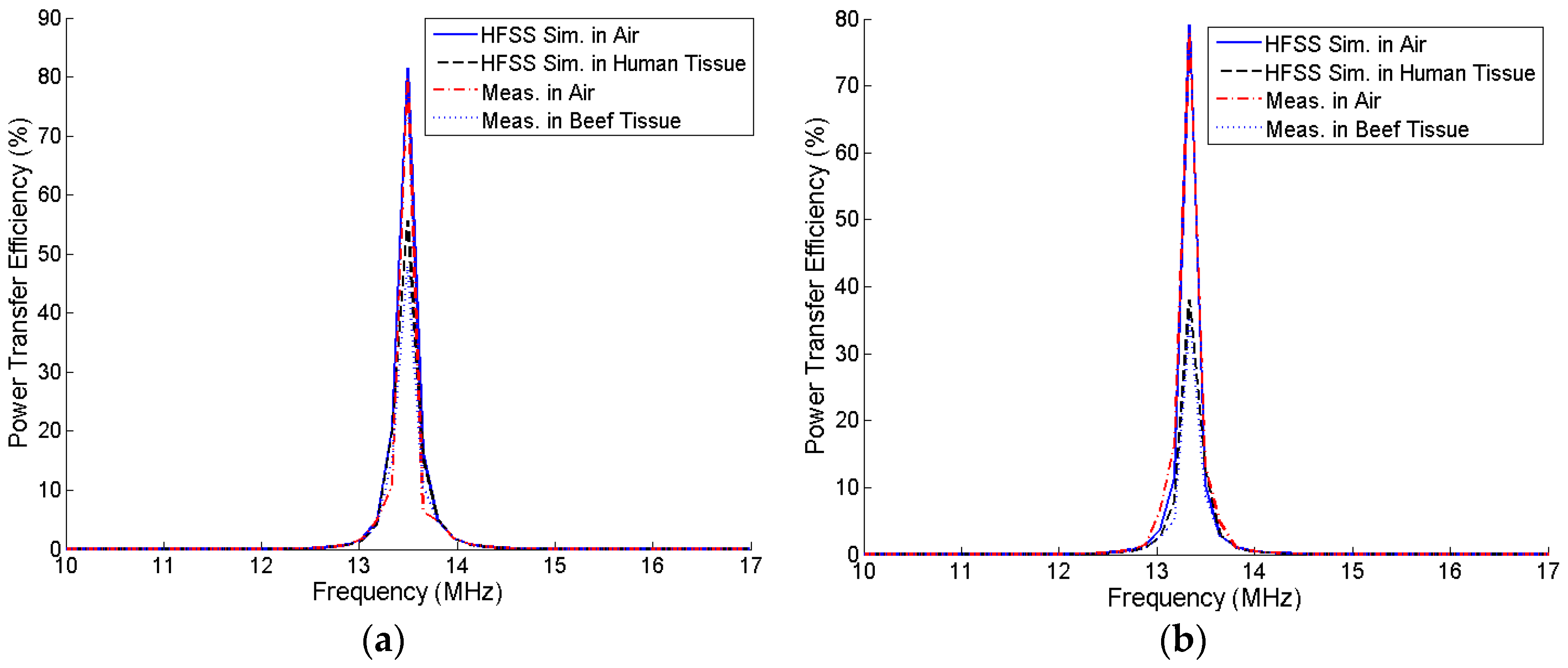
Figure 21 shows the comparison of the simulated and measured PTE of the square and circular PSCs in air and human tissue media under resonance condition. Instead of real human tissue, beef tissue medium was used for the practical measurements. The simulated PTEs of the square and circular coils are degraded to 55.74% and 38.06%, respectively, when the coupling medium between the TX and RX coils is a three-layered human tissue.
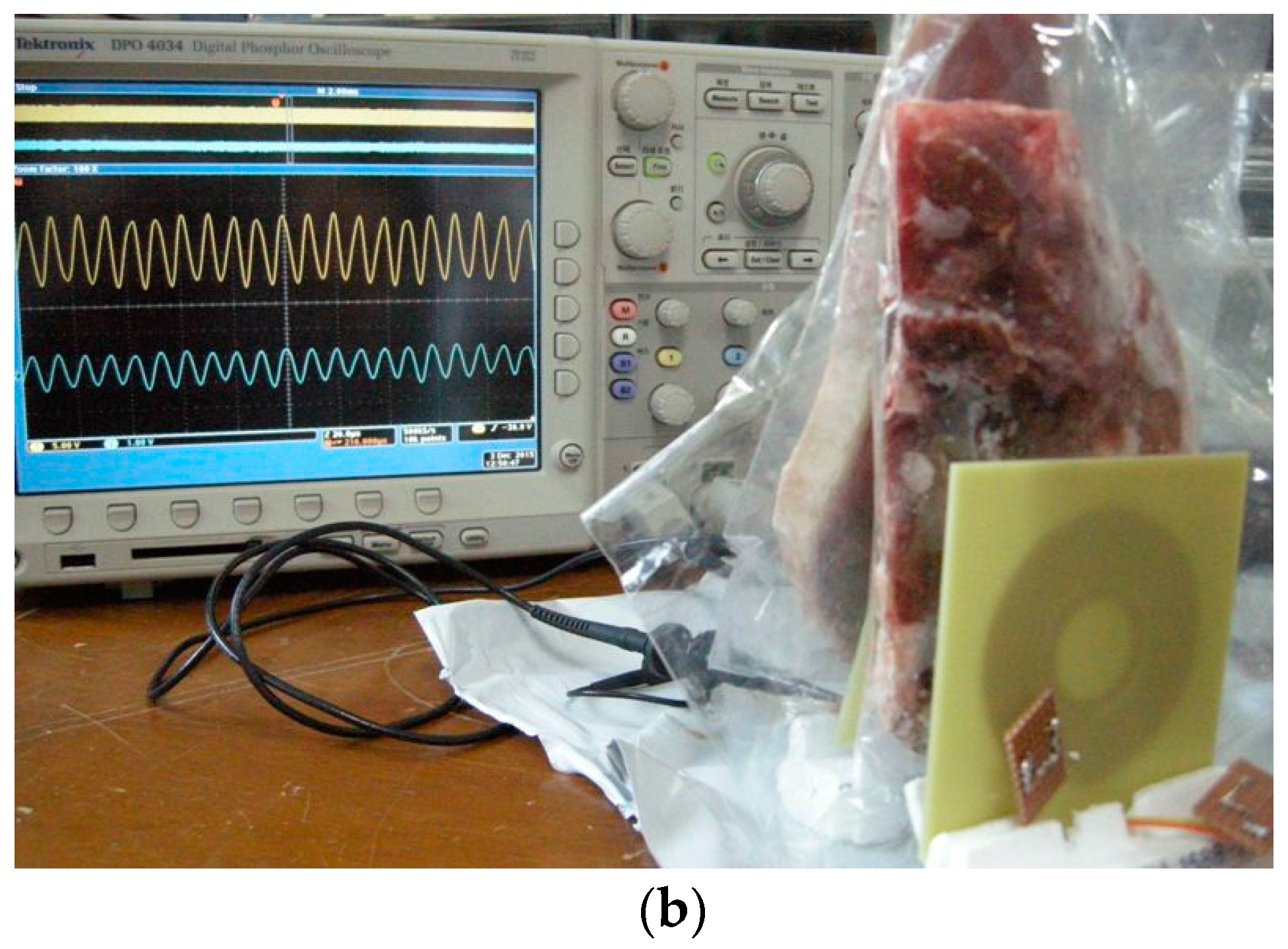
Figure 22 shows the experimental setup to measure the PTE when the coupling medium between the TX and RX coils is 10 mm of beef muscle tissue, which are cut from the lower portion of the ribs. A 20-mm of beef muscle tissue layer is also placed behind the RX coil. The temperature of the beef muscle was 8.7 °C at the time of measurement, and the measured PTE is 48.1% and 35.4%, respectively, for the square and circular PSCs. Due to high permittivity and high conductivity of the biological tissue environment, the Q-factor of each PSC drops significantly. It also affects the parasitic parameters of the PSC. Thus, the PTE is decreased drastically in the biological tissue medium than the air medium.
5. Conclusions
In this paper, a detailed analysis of a fully planar MRC-WPT system for a four-coil-based architecture has been presented for both square and circular structures. The proposed models are optimized using an iterative procedure and fabricated to validate the theoretical modeling. From the analysis, we determined that the circular PSCs require lower self- and mutual inductances than the square PSCs and as a result, the Q-factor and PTE of a circular resonator can be less than those of a square resonator. Another assumption was that a low coupling coefficient can cause a low PTE, but a high PDL due to lower reflection at the load. This phenomenon is also verified. The coupling coefficient of the circular PSC is lower than that of square PSC. Hence, circular PSC provides higher PDL than the square PSC. The designed and fabricated structures are also verified in a biological tissue medium. Very few previous attempts considered the tissue medium. In case of biomedical applications, only an air-medium reference cannot offer an appropriate PTE scenario. On the other hand, most of the previous works overlooked the PDL and only dealt with the PTE performance. Even high- PTE systems can transfer a low PDL. In this work, the PDL for both coil configurations (square and circular) are measured and compared. Although the biological tissue medium reduces the PTE, the amount of power that can be received by the designed square or circular implanted coil remains sufficient to drive a sub-micron technology-based bio-implantable device. Misalignment between external and internal coils is very important issue in a transcutaneous system. Thus, the effect of misalignment on PTE is characterized and practically observed. Compactness of the implanted coil is a major requirement for biomedical applications. A fully planar architecture is more suitable than a simple planar or Litz coil- based resonators in this manner. Thus, the proposed four-coil fully planar MRC-WPT can be a good candidate for biomedical devices.


