Article

Fatigue Damage Evaluation of Short Carbon Fiber Reinforced Plastics Based on Phase Information of Thermoelastic Temperature Change

1
Department of Mechanical Engineering, Kobe University, Kobe 657-8501, Japan
2
DIC Corporation, Tokyo 103-8233, Japan
*
Author to whom correspondence should be addressed.
Sensors 2017, 17(12), 2824; https://doi.org/10.3390/s17122824
Submission received: 14 November 2017 / Revised: 30 November 2017 / Accepted: 1 December 2017 / Published: 6 December 2017

Abstract

:
Carbon fiber-reinforced plastic (CFRP) is widely used for structural members of transportation vehicles such as automobile, aircraft, or spacecraft, utilizing its excellent specific strength and specific rigidity in contrast with the metal. Short carbon fiber composite materials are receiving a lot of attentions because of their excellent moldability and productivity, however they show complicated behaviors in fatigue fracture due to the random fibers orientation. In this study, thermoelastic stress analysis (TSA) using an infrared thermography was applied to evaluate fatigue damage in short carbon fiber composites. The distribution of the thermoelastic temperature change was measured during the fatigue test, as well as the phase difference between the thermoelastic temperature change and applied loading signal. Evolution of fatigue damage was detected from the distribution of thermoelastic temperature change according to the thermoelastic damage analysis (TDA) procedure. It was also found that fatigue damage evolution was more clearly detected than before by the newly developed thermoelastic phase damage analysis (TPDA) in which damaged area was emphasized in the differential phase delay images utilizing the property that carbon fiber shows opposite phase thermoelastic temperature change.

1. Introduction

Carbon fiber reinforced plastic (CFRP) has been widely employed for the primary structural members of transportation vehicles such as automobile, aircraft, or spacecraft, utilizing its excellent specific strength and specific rigidity in contrast with the metal. Short carbon fiber composite materials have been receiving a lot of attentions because of their excellent moldability and productivity. However, they show complicated behaviors in fatigue fracture due to their random fibers orientation. Therefore, effective nondestructive evaluation techniques are required for detecting and measuring various types of damages—such as fiber breakage, matrix cracking, and delamination—during fatigue fracture. Nondestructive evaluation techniques using infrared thermography, i.e., thermographic NDT has been effectively employed for the detection of delamination defects in fiber reinforced plastics. The thermographic NDT techniques based on thermal insulation effect by the delamination defect have been applied to the nondestructive testing of composite materials. The combination of active pulse heating and subsequent transient temperature measurement was effectively employed for sensitive detection of delamination damage in composites. Avdelidis et al. [1,2] reviewed NDT techniques using transient temperature distribution for CFRP as well as data processing techniques for pulsed thermography. Chatterjee et al. [3] compared the defect imaging performance among three transient thermography techniques, e.g., pulsed, lock-in, and frequency modulated thermography. Maldague et al. [4] developed pulse phase infrared thermography for improving the resolution of defect images and contributed to nondestructive evaluation of composite materials. As the transient temperature data analysis scheme, principal component analysis (PCA) has been investigated by several researchers to extract small changes in temperature trends [5,6,7].
In contrast with these thermal insulation techniques, damage evaluation techniques based on the thermoelastic stress analysis (TSA) using infrared thermography were examined for CFRP composites. TSA is a well-established experimental technique for the evaluation of the stress field in isotropic materials, and it has come into widespread use in the industry as an effective, experimental, full-field stress measurement technique [8,9,10,11,12]. Innovative research works on the TSA technique are found in structural integrity evaluations for steel structures related with fracture mechanics evaluations and/or fatigue damage analyses. As for steel structural members, evaluation schemes of the fracture mechanics parameters have been investigated, taking advantage of the TSA technique [13]. The fracture mechanics parameters such as stress intensity factor or J-integral have been directly determined from stress distribution around crack tips [14,15]. These techniques have been successfully applied to the fatigue life assessment for metallic materials. Tomlinson et al. [16] investigated fatigue crack propagation under mixed mode loading. Diaz et al. [17] applied their improved TSA technique for evaluating stress intensity factors in the fatigue test of weld specimen, demonstrating the feasibility of TSA for crack growth analysis influenced by crack closure or residual stress field.
Thermoelasticity for orthotropic materials have been studied by many researchers and the TSA technique has been employed as a powerful tool for evaluating impact or fatigue damage in composite materials and structures [18,19,20,21,22]. Paynter and Dutton [23] applied the TSA technique to wind turbine blade composite structure with successful results on damage evaluation using second harmonic signal correlation. Jones and Molent [24] showed the applicability of the TSA technique for in situ measurement during redesign, reinforcement or repair in aircraft structures. Emery and Dulieu-Barton [25] applied the TSA technique to fatigue damage evaluation in laminated glass fiber epoxy materials, in which TSA was employed as a powerful experimental tool for analyzing complicated fatigue damages such as fiber breakage, matrix cracking, and delamination damage in composites. Fruehmann and Dulieu-Barton [26] applied the TSA technique for the assessment of fatigue damage evolution in woven composite materials. Uenoya and Fujii [27] developed thermoelastic damage analysis (TDA) for the early damage detection in plain-woven CFRP. Yoshida et al. [28] applied TSA technique for the characterization of impact damages in cross-plied carbon fiber/thermoplastic composites.
The present authors [29] investigated the relationship between the fiber orientation angles and the phase delay of the thermoelastic temperature change from the applied loading signal. In this study, distributions of the thermoelastic temperature change and its phase delay were measured for short carbon fiber reinforced plastics during fatigue testing. The relationship between the phase difference and fiber orientation angle was investigated to develop a new thermoelasticity approach for fatigue damage identification for the short carbon fiber reinforced plastics. Fatigue damages were evaluated according to the conventional TDA procedure [27] as well as the newly developed phase-delay based damage characterizing technique “thermoelastic phase damage analysis (TPDA)”.

2. Thermoelastic Stress Analysis Using Infrared Thermography

Dynamic stress change cause a very small temperature change under adiabatic conditions in a solid. This phenomenon is known as the thermoelastic effect and is described by Lord Kelvin’s equation [30], which relates the temperature change (∆TE) to the sum of the changes in the principal stresses (∆σ) under cyclic variable loading as follows.
Δ T E = α ρ C p T Δ σ = k T Δ σ
Here, α is the coefficient of thermal expansion, ρ is the mass density, Cp is the specific heat at constant pressure and T is the absolute temperature. The coefficient k is called thermoelastic constant. The sum of the changes in the principal stresses (∆σ) is obtained by measuring the temperature change (∆TE) using infrared thermography.
As thermoelastic temperature changes are very small and sometimes hidden by the thermal noise of the infrared camera, lock-in infrared thermography using reference signals synchronized with the stress changes is commonly employed to improve the accuracy of stress measurements. The TSA technique uses a lock-in algorithm with a reference-loading signal extracted from the load cell or strain gauge to improve the signal–noise ratio.
When a tension and compression loading in sinusoidal waveform as shown in Figure 1 is applied to materials with positive value of thermoelastic constant k, the thermoelastic temperature change shows opposite phase waveform against the loading waveform. In this study, the value of the phase difference ∆θE was defined as the difference in phase between the thermoelastic temperature change and the loading signal as shown in the figure. In this case, phase difference ∆θE is 180 deg. In this study, thermoelastic temperature measurement was conducted for the short carbon fiber reinforced plastics, and the thermoelastic temperature change ∆TE and the phase difference ∆θE was obtained from experimental data.

3. Experimental Setup

Configurations of the CFRP specimen employed in this study are shown in Figure 2. The specimens were cut from laminated short fiber CFRP sheet with vinyl ester resin and 25.4 mm long carbon fiber bundles. Each bundle was composed of 12,000 short carbon fibers. The mass content (wt %) of resin and fiber was 67 and 33, respectively. The specimen has circular notches with a radius of 2 mm.
Cyclic-axis sinusoidal waveform loading with a frequency f of 7 Hz and a stress ratio R = 0.1 was applied to the specimen by an electrohydraulic fatigue testing machine. Microscopic visible images on the specimen surface and side surface were taken by optical microscope. The temperature change on the specimen surface was measured by infrared thermography with an MCT array detector (CEDIP Inc. (FLIR Systems Inc.), Croissy Beaubourg, Fracnce (Wilsonville, OR, USA), Titanium530L). The specifications and setting of this infrared camera are listed in Table 1. The thermoelastic temperature change ∆TE and the phase difference ∆θE were obtained from experimental data as shown in the forgoing paragraph.

4. Experimental Results

4.1. Effect of Fiber Orientation on Thermoelastic Temperature Change

Before conducting fatigue test, the effect of the fiber orientation angle on the thermoelastic temperature change was experimentally investigated using a CFRP specimen without notches. Measurement of the thermoelastic temperature change was conducted under the applied maximum stress σmax = 100 MPa. The fiber orientation angle φf is defined as shown in Figure 3; thus φf is equal to 0 degrees when a fiber bundle is oriented in parallel with the loading axis. The distribution of the fiber orientation angle φf was measured after the thermoelastic stress measurement as described below: (1) surface thin resin layer was removed by polishing for exposing carbon fiber bundles; (2) optical image of the surface carbon fiber bundles was taken by digital camera; (3) fiber orientation angle φf was determined by image processing program developed by Enomae [31].
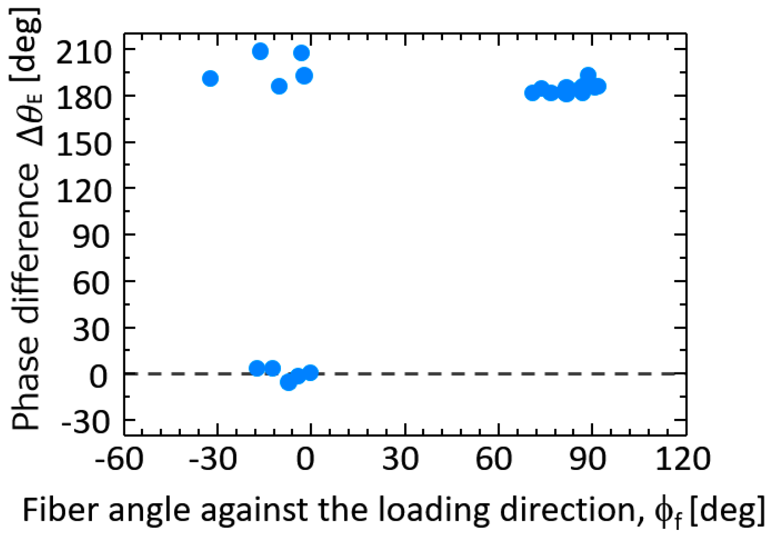
Obtained optical image of the sample surface, distribution of fiber orientation angles, and thermoelastic temperature change ∆TE obtained for CFRP specimen without notches are shown in Figure 4. The relationship between the thermoelastic temperature change and the fiber orientation angle φf is shown in Figure 5. It is found from these figures that ∆TE measured in the area where φf is around 90° takes higher values compared with those measured in the area where φf is around 0°. Furthermore, the relationship between the fiber orientation angle φf and the phase difference ∆θE is shown in Figure 6. It can be seen from the figure that the phase difference ∆θE takes the value of 180° where the fiber orientation angles are around 90°. On the other hand, ∆θE takes 0° where φf is around 0°.
It was reported by Sugimoto and Ishikawa [32] that the coefficient of thermal expansion of carbon fiber in longitudinal direction has negative value, hence the thermoelastic constant k of unidirectional CFRP takes negative value. It is supposed that carbon fibers mainly shared the applied axial load in the region where the orientation angles of the carbon fiber bundles are 0° (parallel with the loading axis). Therefore, the thermoelastic temperature change showed a coordinate-phase waveform with that of applied loading.

4.2. Fatigue Damage Identification Based on Thermoelastic Temperature Change and Its Phase Delay Information

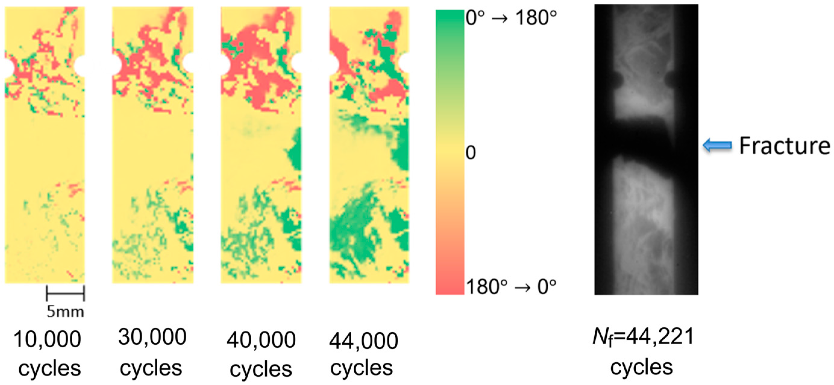
Fatigue test was conducted for the short carbon fiber reinforced plastic specimen with circular notches under the applied maximum stress σmax = 180 MPa. As described in the introduction, Uenoya et al. [25] developed the thermoelastic damage analysis (TDA) for the early damage detection in plain-woven long carbon fiber reinforced plastics. In this technique, a differential thermoelastic temperature distribution image was generated by subtracting an image of thermoelastic temperature change obtained at certain loading cycle from a reference initial image of thermoelastic temperature change. Fatigue damage evolution causes local stress change, and this is emphasized in the differential thermoelastic temperature distribution image. Therefore, the fatigue damage in CFRP sample can be detected in the differential thermoelastic temperature distribution image at the early stage in the fatigue life. In this study, the reference initial image of thermoelastic temperature change was set at 200 cycles. The obtained TDA images at 10,000; 30,000; 40,000; and 44,000 cycles are shown in Figure 7, with the infrared image obtained after failure of the CFRP specimen at 44,221 cycles. It is found from TDA images that the thermoelastic temperature change ∆TE on the fracture part was decreasing with the increasing loading cycles. And the decreasing area of ∆TE was expanded in the transverse direction of the specimen. This indicates that fatigue damage can be detected from the local stress change caused by the change in load sharing conditions due to the damage evolution.
Distribution of the phase difference ∆θE obtained at 200; 10,000; 30,000; 40,000; and 44,000 cycles are shown in Figure 8. Change in phase values were found in the region where the structural fracture of CFRP sample was detected. The phase values were changed from 0 to 180°, and the phase change region was expanded with the increasing loading cycles. As described in the foregoing paragraph, ∆θE = 0° means that the thermoelastic effect of carbon fiber bundles is predominant, on the other hand ∆θE = 180° means that the thermoelastic effect of matrix resin is predominant. The change in phase values indicates the change of load sharing conditions between resin and carbon fiber bundles due to the fatigue damage evolution. We thought that high-sensitivity early fatigue damage detection technique can be developed by utilizing the change in phase difference ∆θE; we propose a thermoelastic phase damage analysis (TPDA). In TPDA a differential phase delay distribution image is generated by subtracting a phase delay image obtained at certain loading cycle from a reference initial phase image. In this study the reference initial phase delay image was set at 200 cycles. The obtained TPDA images at 10,000; 30,000; 40,000; and 44,000 cycles are shown in Figure 9. It was found from TPDA images that the significant change of phase values from 0 to 180° (indicated green color in the figures) was found in the region where the structural fracture was detected.
In this experiment, visible images on the side surfaces of the CFRP specimen were taken by digital microscope. Microscopic visible images taken at 30,000; 35,000; and 40,000 loading cycles are shown in Figure 10 compared with TPDA results. The microscopic imaging area was indicated by red broken lines in the figures. It was found that delamination damage was initiated at 30,000 cycles and it grew and reached the front surface of the specimen (infrared observation side). TPDA images show the change in phase values was clearly detected in the region where the delamination fracture was initiated. The phase values were changed from 0 to 180°, and the phase change region was expanded with the increasing loading cycles. As described in the foregoing paragraph, ∆θE = 0° means that the thermoelastic effect of carbon fiber bundles is predominant, on the other hand ∆θE = 180° means that the thermoelastic effect of matrix resin is predominant. The change in phase values indicates the change of load sharing conditions between resin and carbon fiber bundles due to the evolution of delamination damage.

5. Conclusions

In this study, TSA using an infrared thermography was applied to the evaluation of fatigue damage in short carbon fiber composites. In addition to the conventional thermoelastic damage analysis, the phase difference between the thermoelastic temperature change and the applied loading signal was measured for short carbon fiber reinforced plastics. Obtained results are summarized as follows:
(1)
It was found from the relationship between the thermoelastic temperature change ∆TE and the fiber orientation angle φf that ∆TE in the area where φf = 90° takes higher value compared with that in the area where φf = 0°.
(2)
It was also found from the relationship between the fiber orientation angle φf and the phase difference ∆θE that ∆θE takes 180° in the area where φf = 90°. On the other hand, ∆θE takes 0° where φf = 0°. This is due to the negative thermoelastic constant of carbon fibers and the load sharing condition between resin and carbon fibers.
(3)
Fatigue damage was evaluated according to the conventional TDA procedure as well as the newly developed phase-delay based damage characterizing technique “thermoelastic phase damage analysis (TPDA)”. It was found from TPDA images that the significant change of phase values from 0 to 180° (indicating the change in load sharing condition between resin and carbon fibers due to fatigue damage evolution) was found in the region where the structural fracture was detected.

Acknowledgments

The authors would like to acknowledge that this research was partly supported by a Grant-in-Aid for Scientific Research from the Japan Society for the Promotion of Science (B: 26289009).

Author Contributions

The work presented in this paper was a collaboration of all authors. S. Nonaka and K. Hamada made the specimen. Y. Nakamura acquired and processed the experimental data. D. Shiozawa and T. Sakagami analysis and contributed writing the paper. The manuscript was discussed by all authors.

Conflicts of Interest

The authors declare no conflict of interest.

References

  1. Avdelidis, N.P.; Almond, D.P.; Dobbinson, A.; Hawtin, B.C.; Ibarra-Castanedo, C.; Maldague, X. Aircraft composites assessment by means of transient thermal NDT. Prog. Aerosp. Sci. 2004, 40, 143–162. [Google Scholar] [CrossRef]
  2. Avdelidis, N.P.; Gan, T.-H. Non-destructive evaluation (NDE) of Composites: Infrared (IR) thermography of wind turbine blades. In Non-Destructive Evaluation (NDE) of Polymer Matrix Composites; Karbhari, V.M., Ed.; Woodhead Publishing Limited: Cambridge, UK, 2013; pp. 634–648. ISBN 978-0-85709-344-8. [Google Scholar]
  3. Chatterjee, K.; Tuli, S.; Pickering, S.G.; Almond, D.P. A comparison of the pulsed, lock-in and frequency modulated thermography nondestructive evaluation techniques. NDT E Int. 2011, 44, 655–667. [Google Scholar] [CrossRef] [Green Version]
  4. Maldague, X.; Marinetti, S. Pulse phase infrared thermography. J. Appl. Phys. 1996, 79, 2694–2698. [Google Scholar] [CrossRef]
  5. Rajic, N. Principal component thermography for flaw contrast enhancement and flaw depth characterization in composite structures. Compos. Struct. 2002, 58, 521–528. [Google Scholar] [CrossRef]
  6. Griefahn, D.; Wollnack, J.; Hintze, W. Principal component analysis for fast and automated thermographic inspection of internal structures in sandwich parts. J. Sens. Sens. Syst. 2014, 3, 105–111. [Google Scholar] [CrossRef]
  7. Marinetti, S.; Grinzato, E.; Bison, P.G.; Bozzi, E.; Chimenti, M.; Pieri, G.; Salvetti, O. Statistical analysis of IR thermographic sequences by PCA. Infrared Phys. Technol. 2004, 46, 85–91. [Google Scholar] [CrossRef]
  8. Greene, R.J.; Patterson, E.A.; Rowlands, R.E. Thermoelastic Stress Analysis. In Springer Handbook of Experimental Solid Mechanics; Sharpe, W.N., Jr., Ed.; Springer Science + Business Media, LLC: New York, NY, USA, 2008; pp. 743–767. ISBN 978-0-387-26883-5. [Google Scholar]
  9. Dulieu-Barton, J.M.; Stanley, P. Development and applications of thermoelastic stress analysis. J. Strain Anal. Eng. Des. 1998, 33, 93–104. [Google Scholar] [CrossRef]
  10. Dulieu-Barton, J.M. Introduction to thermoelastic stress analysis. Strain 1999, 35, 35–39. [Google Scholar] [CrossRef]
  11. Pitarresi, G.; Patterson, E.A. A review of the general theory of thermoelastic stress analysis. J. Strain Anal. Eng. Des. 2003, 38, 405–417. [Google Scholar] [CrossRef]
  12. Sakagami, T. Remote nondestructive evaluation technique using infrared thermography for fatigue cracks in steel bridges. Fatigue Fract. Engng. Mater. Struct. 2015, 38, 755–779. [Google Scholar] [CrossRef]
  13. Tomlinson, R.A.; Olden, E.A. Thermoelasticity for the analysis of crack tip stress fields—A review. Strain 1999, 35, 49–55. [Google Scholar] [CrossRef]
  14. Ju, S.H.; Lesniak, J.R.; Sandor, B.I. Numerical simulation of stress intensity factors via the thermoelastic technique. Exp. Mech. 1997, 37, 278–284. [Google Scholar] [CrossRef]
  15. Diaz, F.A.; Patterson, E.A.; Tomlinson, R.A.; Yates, J.R. Measuring stress intensity factors during fatigue crack growth using thermoelasticity. Fatigue Fract. Engng. Mater. Struct. 2004, 27, 571–583. [Google Scholar] [CrossRef]
  16. Tomlinson, R.A.; Marsavina, L. Thermoelastic investigations for fatigue life assessment. Exp. Mech. 2004, 44, 487–494. [Google Scholar] [CrossRef]
  17. Diaz, F.A.; Yates, J.R.; Patterson, E.A. Some improvements in the analysis of fatigue cracks using thermoelasticity. Int. J. Fatigue 2004, 26, 365–376. [Google Scholar] [CrossRef]
  18. Lin, S.T.; Rowlands, R.E. Thermoelastic stress analysis of orthotropic composites. Exp. Mech. 1995, 35, 257–265. [Google Scholar] [CrossRef]
  19. Dulieu-Barton, J.M.; Stanley, P. Applications of thermoelastic stress analysis to composite materials. Strain 1999, 35, 41–48. [Google Scholar] [CrossRef]
  20. Emery, T.R.; Dulieu-Barton, J.M.; Earl, J.S.; Cunningham, P.R. A generalised approach to the calibration of orthotropic materials for thermoelastic stress analysis. Compos. Sci. Technol. 2008, 68, 743–752. [Google Scholar] [CrossRef]
  21. Palumbo, D.; De Finis, R.; Demelio, G.P.; Galietti, U. Study of damage evolution in composite materials based on the Theroelastic Phase Analysis (TPA) method. Compos. Part B Eng. 2017, 117, 49–60. [Google Scholar] [CrossRef]
  22. Sfarra, S.; Perilli, S.; Ambrosini, D.; Paoletti, D.; Nardi, I.; de Rubeis, T.; Santulli, C. A proposal of a new material for greenhouses on the basis of numerical, optical, thermal and mechanical approaches. Constr. Build. Mater. 2017, 155, 332–347. [Google Scholar] [CrossRef]
  23. Paynter, R.J.H.; Dutton, A.G. The use of a second harmonic correlation to detect damage in composite structures using thermoelastic stress measurements. Strain 2003, 39, 73–78. [Google Scholar] [CrossRef]
  24. Jones, R.; Molent, L. Application of constitutive modeling and advanced repair technology to F111C aircraft. Compos. Struct. 2004, 66, 145–157. [Google Scholar] [CrossRef]
  25. Emery, T.R.; Dulieu-Barton, J.M. Thermoelastic Stress Analysis of damage mechanisms in composite materials. Compos. Part A 2010, 41, 1729–1742. [Google Scholar] [CrossRef]
  26. Fruehmann, R.K.; Dulieu-Barton, J.M.; Quinn, S. Assessment of fatigue damage evolution in woven composite materials using infra-red techniques. Compos. Sci. Technol. 2010, 70, 937–946. [Google Scholar] [CrossRef]
  27. Uenoya, T.; Fujii, T. Damage characterization of woven fabric composite materials by thermoelastic analysis. J. Soc. Mater. Sci. Jpn. 2000, 49, 941–947. [Google Scholar] [CrossRef]
  28. Yoshida, T.; Uenoya, T.; Miyamoto, H. Impact damage characterization in cross-plied carbon fiber/ thermoplastic composites using thermoelastic stress analysis. Proc. SPIE 2012, 8347. [Google Scholar] [CrossRef]
  29. Sakagami, T.; Shiozawa, D.; Nakamura, Y.; Nonaka, S.; Hamada, K. Fatigue damage evaluation of short fiber CFRP based on phase information of thermoelastic temperature change. Proc. SPIE 2017, 10214. [Google Scholar] [CrossRef]
  30. Thomson, W. On the dynamical theory of heat. Trans. R. Soc. 1853, 20, 261–283. [Google Scholar]
  31. Enomae, T. FiberOri8single03.exe. Available online: http://www.enomae.com/FiberOri/index.htm (accessed on 4 December 2017).
  32. Sugimoto, S.; Ishikawa, T. Examination of quantitative infrared stress measurement of CFRP laminates and its application to non-destructive evaluation. Tech. Rep. Natl. Aerosp. Lab. 1999, 1396, 1–23. [Google Scholar]
Figure 1. Definition of phase in thermoelastic temperature change.
Sensors 17 02824 g001
Figure 2. Configurations of employed short carbon fiber reinforced plastic specimen.
Sensors 17 02824 g002
Figure 3. Definition of fiber orientation angle.
Sensors 17 02824 g003
Figure 4. Fiber orientation angles and thermoelastic temperature change (σmax = 100 MPa, f = 7 Hz): (a) optical image; (b) orientation angle; (c) thermoelastic temperature change.
Sensors 17 02824 g004
Figure 5. Relationship between thermoelastic temperature change ∆TE and fiber orientation angle φf.
Sensors 17 02824 g005
Figure 6. Relationship between phase difference ∆θE and fiber orientation angle φf.: the phase difference ∆θE was measured for specimen in Figure 4 and Figure 5 under σmax = 100 MPa and f=7 Hz.
Sensors 17 02824 g006
Figure 7. TDA images and infrared image obtained after specimen failure (σmax = 180 MPa, f = 7 Hz).
Sensors 17 02824 g007
Figure 8. Distribution of phase delay measured at increasing loading cycles (σmax = 180 MPa, f = 7 Hz).
Sensors 17 02824 g008
Figure 9. Results of thermoelastic phase damage analysis (TPDA) indicating early fatigue damage evolution (σmax = 180 MPa, f = 7 Hz).
Sensors 17 02824 g009
Figure 10. Microscopic visible images of specimen side surface indicating delamination damage evolution (σmax = 180 MPa, f = 7 Hz).
Sensors 17 02824 g010
Table 1. Specifications and setting of employed infrared camera
Infrared DetectorMCT
Detectable wavelength7.7–9.3 μm
Number of detectors320 × 256
Temperature resolution (NETD)25 mK
Framing rate373 Hz
Time of data acquisition10 s