1. Introduction
There are approximately 39 million legally blind people in the world, while another 246 million people have some form of significant visual impairment [
1]. Among them, the number of older people is increasing due to age-related diseases such as glaucoma and diabetic retinopathy. In their daily lives, these people experience many difficulties when traversing unfamiliar environments on the way to their destination. For this type of wayfinding, it is essential to use and organize definite sensory cues from the external environment [
2,
3,
4]. In general, sighted people construct 3D maps based on visual sensory information. In contrast, visually impaired people use different cognitive and attentional resources. As discussed in [
5], people who are born blind or become blind early in life encode the sequential features of a travelled route, i.e., they create a set of instructions that denote directional changes in the route.
To reduce the difficulties of the visually impaired and help them localize a current position and find a destination, a wide range of technologies have been developed [
3,
6,
7,
8,
9,
10,
11,
12,
13,
14,
15,
16,
17,
18,
19,
20,
21,
22,
23,
24,
25,
26,
27,
28,
29,
30,
31,
32]. The most recent research and technologies have focused on Global Positioning Systems (GPS) systems [
6,
7]. However, while systems using GPS sensors operate well as wayfinding aids in outdoor environments, GPS signals are often unavailable in indoor environments, which makes them inadequate for assisting people indoors. Accordingly, the goal of the present study was to develop a wayfinding system that will be effective in various indoor environments with complex illumination patterns and cluttered backgrounds such as shopping malls, hospitals, and schools.
Thus far, various solutions for indoor wayfinding have been proposed and implemented. They can be categorized as either sensor-based approaches [
8,
9,
10,
11,
12,
13,
14,
15,
16,
17,
18,
19,
20,
21] or vision-based approaches [
22,
23,
24,
25,
26,
27,
28,
29,
30,
31,
32]. The former use sensors, such as Wi-Fi, RFID, and UWB sensors, to estimate a user’s current position, and the latter use images obtained from a camera and recognize visual clues, such as objects and scene texts, from the surrounding environment. Among these potential solutions, vision-based methods have received more attention from researchers, and, in particular, systems with color codes have been successfully investigated for use in various applications [
26,
27,
28,
29,
30,
31,
32].
To help blind and visually impaired people with wayfinding, two basic functions should be supported: positioning (to localize a user’s position) and path guidance (to guide a user through a route to the target destination and the return route) [
30]. To support such functions, most existing systems require the indoor structural information of buildings such as maps and building layouts. Typically, these systems obtain such information through seamless communication between a user’s mobile device and server systems, or some systems assume that a building map has been provided previously. However, in real situations, this assumption is not always true, and access to such structural information may be limited to authorized people only and is generally not common knowledge for the public. Moreover, stable communication between the server and mobile user is not guaranteed due to signal interruptions or traffic. Thus, it is necessary to develop wayfinding systems that can function in various environments regardless of the availability of maps.
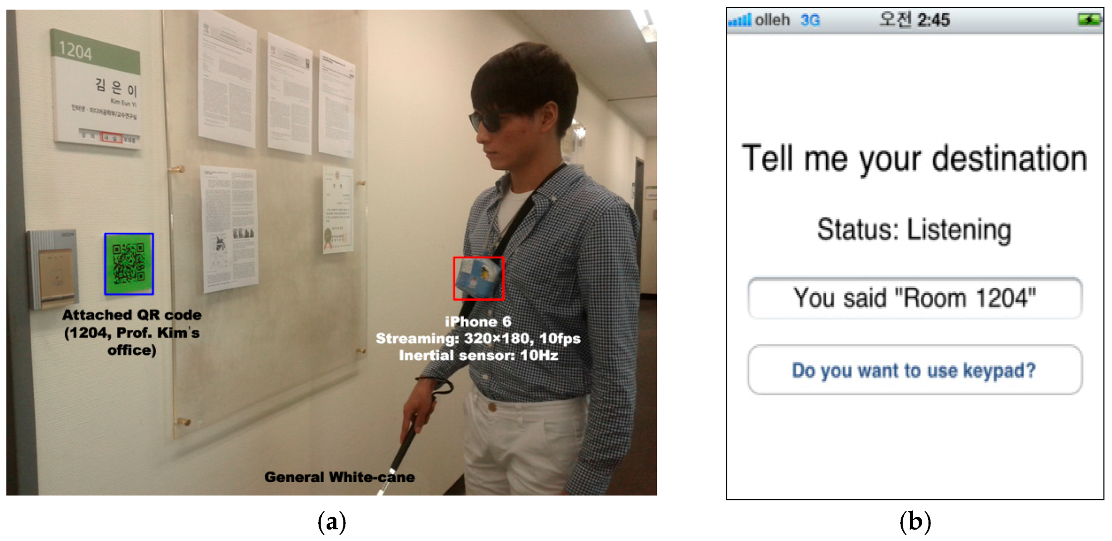
For the design of a wayfinding system, we conducted an initial study on the wayfinding behaviors of visually impaired people and sighted people. We collected and analyzed the behaviors that perceive the environmental information such as the moving direction or location, and determined the next actions on the way to a given destination. In general, visually impaired people depend on a white cane to understand the environmental information. Using the white cane, they can understand the situation through detecting changes in the walls, including corners, and the ground height. When the place type changed, they determined their next actions such as finding braille signs next to the door, turning left or right according to the corner, or going up stairs. These observations signify that recognizing the current situation is essential to enabling safe travel and determining their way.
Sighted people can navigate unfamiliar indoor environments even if they do not have the structural information because they can locate the necessary information from visual clues such as objects and signs within the environment. An interesting point is that the sighted people require different types of information according to their situation. For example, when they are standing in front of a door, they need information about the room number in order to know whether it is their intended destination. For a junction or hall, they need directional information about their destination.
Based on these observations, we propose a situation-based wayfinding system that first recognizes the situation and then locates the appropriate environmental information. In this study, a situation refers to the type of place where the user is standing, and it is classified as a door, corridor, hall, or junction. In order to represent different environmental information, two types of QR code were designed: one encodes location-specific information and the other encodes directional information. These QR codes are attached according to the place type.
The proposed system was implemented on an iPhone 6, which has an embedded camera, gyroscope, and accelerometer. It consists of five processing modules: situation awareness, object detection, object recognition, user trajectory recording, and activity-based instruction. The situation awareness module is the core of the proposed system because it determines the type of scene objects to be detected according to the type of current place. For the situation awareness module, some templates that represent the respective situations are first collected. Then, a vocabulary tree is built first from templates, which are used for an effective image description and a fast comparison between images. Then, a new input image is compared with the templates using an entropy-based metric, and its situation is determined based on the most similar template. Once a situation is determined, the necessary environmental information is located. In this proposed approach, this information is represented with color QR codes [
26,
27,
28,
29,
30,
31,
32], which require only minor modifications to the environment such as posting special signs and are widely used in real environments. Then, simple computer vision algorithms based on color and edges are applied to detect the codes on a mobile smartphone quickly and reliably. While a user is moving, their motion is computed continuously, and their routes are recorded in the user trajectory recording module, which are used to guide the return route. Finally, all processed results are conveyed to the user through activity-based instructions. These results guide visually impaired people to the destination using the user’s movement activity paths, such as walking a certain number of steps and compass directions, and the users are notified via beeping or text-to-speech (TTS) information.
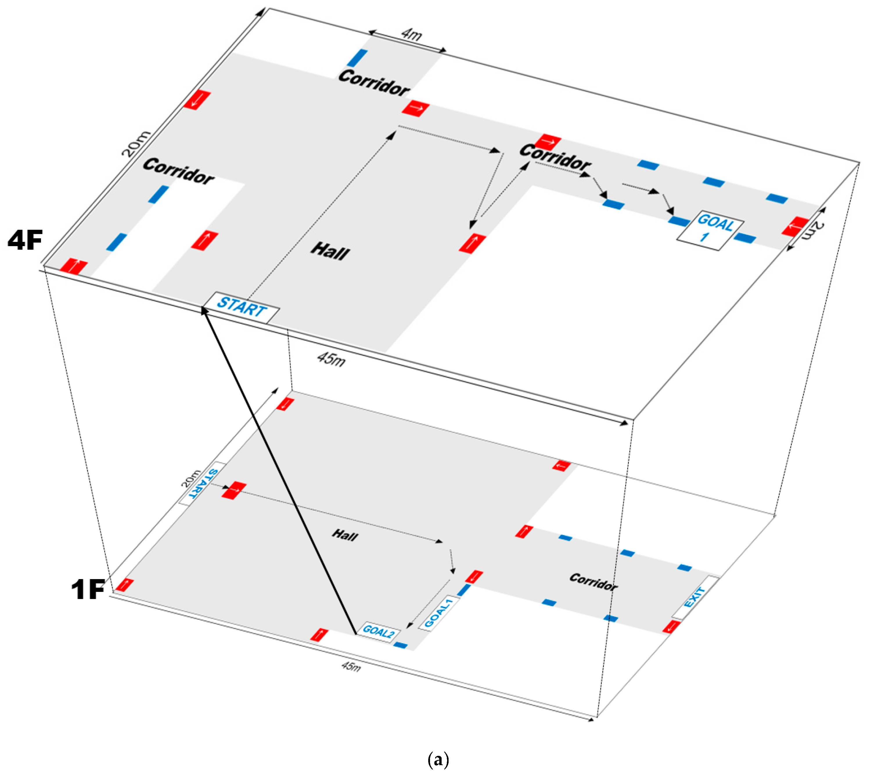
To assess the validity of the proposed method, it was tested in unfamiliar indoor environments with varying illuminations and building layouts. The experimental results show that the proposed system could detect the scene objects with an accuracy of almost 100% at a distance of 2.5 m and a viewing angle of ±40°. Furthermore, it recognized the meaning of an object with an accuracy of more than 99%. In addition, to demonstrate its feasibility as a wayfinding aid for blind and visually impaired people, field tests were conducted with four users. They were all able to locate their path in real-time with an accuracy of 97%.
The reminder of the paper is organized as follows:
Section 2 reviews previous work presented in the literature.
Section 3 presents an overview of the proposed system. The module details are introduced from
Section 4 to
Section 7. The experimental results are reported in
Section 8, followed by the conclusions in
Section 9.
3. Overview of the Proposed System
The goal of the proposed system is to guide blind and visually impaired people to and from their destination of choice in unfamiliar indoor environments to fulfill their accessibility and mobility needs. Here, the primary target user population is people with low vision or blindness. The proposed wayfinding system was implemented on an iPhone6, which has an embedded camera, gyroscope, and accelerometer. Additionally, it supports two functions: positioning and path guidance. Initially, by processing the images obtained from the iPhone camera, the proposed system first recognizes the current situation. Then, it locates scene objects and recognizes their meaning so that it can guide the user along a route to the target destination. Meanwhile, it calculates the user’s motions using the two inertial sensors and records the user’s trajectories, which are used as a guide for the return route.
Figure 3 shows the overall architecture of the proposed wayfinding system. When a user input is given to the system by speech recognition, the proposed system is activated. The information collected from the sensors are continuously processed, and the results are delivered to the user by a Text-To-Speech interface. The proposed system consists of five main modules: situation awareness, object detection, object recognition, user trajectory recording, and user interface with activity-based instructions.
In the situation awareness module, the proposed system first recognizes the user’s situation, which refers to the type of place where the user is standing. This module has an essential function in the proposed system. It can determine what environmental information is required and where the user should traverse by classifying the current types of places as corridors, doors, halls, or junctions. This enables the proposed system to function in various environments even though environmental maps are not available. For the situation awareness module, image matching techniques based on shape descriptors are used. This is discussed in detail in
Section 4.
According to the situation, the required environmental information is different either requiring just location information (door) or requiring both location and directional information (corridor, hall, and junctions). Here, the environmental information is represented by QR codes. The codes were designed with green or orange quiet zones (The quiet zone helps the scanner find the leading edge of the barcode so reading can begin), which enable accurate discrimination from complex environments even when using simple color analysis. Based on the current situation and environmental information, an activity-based instruction is created and conveyed to the user. Then, human activities such as walking a certain number of steps and turning in a certain direction are obtained by calculating the distance between the user and the QR code and the viewing angle. While moving, the user’s path is continuously recorded in the user trajectory recording module, which is used to help the user locate previously visited locations such as his/her starting point.
While the user is moving, the proposed system records all processing results in a log file. Thus, it can manage the unexpected problems that can occur due to battery discharge or sensing failures. If beeping or speech signals are suddenly not generated by the proposed system, the user must stop walking and restart the system. Once the proposed system is restarted, it automatically loads the last log file in order to verify whether the recent recognition results match with the user’s destination or not; if it does not match, the proposed system determines that the previous wayfinding was not completed and asks the user if they want to continue the wayfinding for the previous destination.
4. Situation Awareness
People often move through unfamiliar environments. Even when people have no prior structural information for such environments, they can easily reach their destination. The reason is that sighted people use various types of visual clues that are found in indoor environments to guide them. This section describes how people use visual clues that are found in environments. Based on our observations, we defined important situations and then developed an algorithm that recognizes those situations.
4.1. Initial Study
To collect visual clues that are often observed in real environments, an initial study was conducted. We focused on determining which visual clues are necessary from various objects in the surrounding environment and how people use this information to guide them to their destination. In this initial study, two men and three women were selected who had expert knowledge on the structure and rooms of several buildings at our university campus. Using a digital camcorder, the users recorded useful visual clues that were found in real environments.
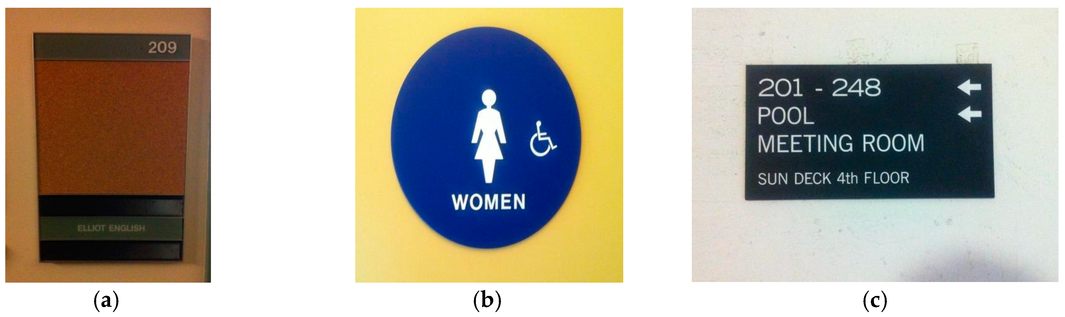
Figure 4 shows some of the visual clues that were observed in real environments.
As seen in
Figure 4, many visual clues can be observed in real environments. Although some differences exist according to the type of building, the visual clues can be divided into two groups:
location-specific information that identifies the current position, and
directional information for a given destination.
In addition, visual clues with positioning information were primarily observed in front of doors, while clues with directional information usually were observed in halls and corridors. For example, place numbers (
Figure 4a) and pictograms (
Figure 4b) were found in front of doors, whereas directional signs were found in a hall or at a junction shown in
Figure 4c.
In addition, in order to analyze the needs of blind people and visually impaired people for the proposed wayfinding system, we observed their behaviors in order to understand how they interpret the environmental information around them. Yang et al. studied their wayfinding behaviors through interviews and through capturing all actions during finding their destination in unfamiliar environments [
40]. In general, the visually impaired people depend on white-cane to understand environmental information. Through alternatively striking the left side and the right side with the white cane, they can perceive the location of obstacles and the available directions toward their destination.
Table 2 presents the user behaviors using the white-cane to understand the environment around them. On flat ground, the visually impaired people first find the nearest wall, and then move forward following the wall. When they move around, it is possible to recognize doors or corridors through changes in the edges and shapes of the walls. On stairs or slopes, they can determine whether to go up or go down through variations in the height of the ground.
Consequently, situation information has an important function in navigation and wayfinding for both sighted people and visually impaired people. Accordingly, it was used as a foundation to develop the proposed system. To improve the mobility of blind or visual impaired people so that they can independently traverse unfamiliar indoor environments, a situation-based navigation and wayfinding system is proposed that first recognizes the type of place and then detects and recognizes the signage.
4.2. Definition of Situations
In this study, a situation refers to the type of place where the user is standing. The situation is categorized into one of four types: door, corridor, hall, and junction. While the first three situations (door, corridor, and hall) are self-contained, the last situation (junction) transposes one situation into another making it a combination of two or more situations. Thus, the first three situations are called primitive place types while the last situation is called a complex place type.
These types of situations have also been considered in other systems. For example, in anti-collision systems, the situations are divided into four types according to the level of difficulty in controlling a wheelchair: in front of a door, in front of an obstacle, a wall, and other situations. Then, the classification is performed based on the sensor information attached to both sides of the wheelchair. The situation is determined according to the difference between the distances measured by the sensors. This approach is unsuitable for mobile phones due to hardware issues; thus, this study proposes a novel vision-based method to recognize various situations.
4.3. Recognition Methods
For situation awareness, specific characteristics must be identified to distinguish the four situation types, that is, the visual patterns associated with each type of situation must be recognized. However, the same type of situation can appear significantly different in images for many reasons including cluttered backgrounds, different viewpoints, orientations, scales, lighting conditions, and so on. Thus, to manage these differences, speeded-up robust feature (SURF) is used. SURF is known as a scale and rotation invariant feature detector [
41]. To establish a link between the four situation types and the SURFs, 200 images representing the four situation types were collected from various environments and used to extract the SURF local descriptors.
Figure 5 shows the characteristics of the detected SURF descriptors corresponding to the four situation types.
Figure 5a,b shows the SURFs overlapping the original images, while
Figure 5c–e shows the accumulated SURF descriptors over 5, 10, and 20 images for each situation type. Interestingly, in
Figure 5c–e, the accumulated SURFs for the corridor images revealed an X-shaped pattern shown in the top images. A rectangular-shaped pattern was observed for the door images (second image from the top). The SURFs for the hall images were crowded around the upper boundaries with a horizontal and thick line pattern in the center. A specific pattern was not detected in the junction image SURFs, which were complexly and sparsely distributed across the images. Thus, common patterns were revealed among the images that belonged to the same situation type, except for the complex junction situation. Therefore, SURF descriptors were used to index the collected sample images and to match the input image with the indexed image to recognize the current situation. A vocabulary tree, which is a very popular algorithm in object recognition, was used for the indexing [
42,
43]. Therefore, the module has two stages: an offline phase to build the vocabulary tree and an online phase to recognize the current situation.
4.3.1. Offline Stage
First, 200 images were collected for the template data to represent the four situation types from various environments, and 20,289 SURF descriptors were extracted from the local regions in the images. Then, the extracted descriptors were quantized into visual words by the hierarchical
K-means [
42,
43]. Here,
K defines the branch factor (number of children of each internal node), not the number of clusters, and it was set at 10.
The process for the hierarchical
K-means quantization is as follows. First, an initial clustering is performed on the 20,289 initial descriptors, thereby defining the
K groups, where each group consists of the descriptor vectors closest to a particular cluster center. This process is performed recursively, and a vocabulary tree is built. Each node in the vocabulary tree is an associated inverted file with reference to the images containing the descriptor that corresponds to that node. Once the quantization is defined, an entropy-based weight (
) is assigned to each node (
i), as follows:
where
N is the number of images in the template database, and
Ni is the number of images in the database with at least one descriptor vector path through node
i. Inspired by the TF-IDF scheme [
42], this is used to ignore the effects of the most frequent and infrequent features (noise) in the template database.
4.3.2. Online Stage
The online phase determines the most relevant images in the template database in relation to the current input image, which is calculated based on the similarity of the paths down the vocabulary tree of the descriptors from the DB images and those from the input image. According to the weights assigned to each node in the vocabulary tree, the template data (
t) and input image (
q) are defined as follows:
where
and
are the number of descriptor vectors with a path through node
i in the template and input image, respectively. To compute the difference between the template and input vectors, both vectors are normalized, and then, the similarity is calculated using the following dot product.
The template image with the highest matching score is selected, and its situation type is assigned to label the current situation.
5. Object Detection and Recognition
It is difficult to recognize normal signage such as numbers and pictures due to their complex shapes, varieties, and distance. Due to these difficulties, color codes have been used extensively to replace normal signage [
26,
27,
28,
29,
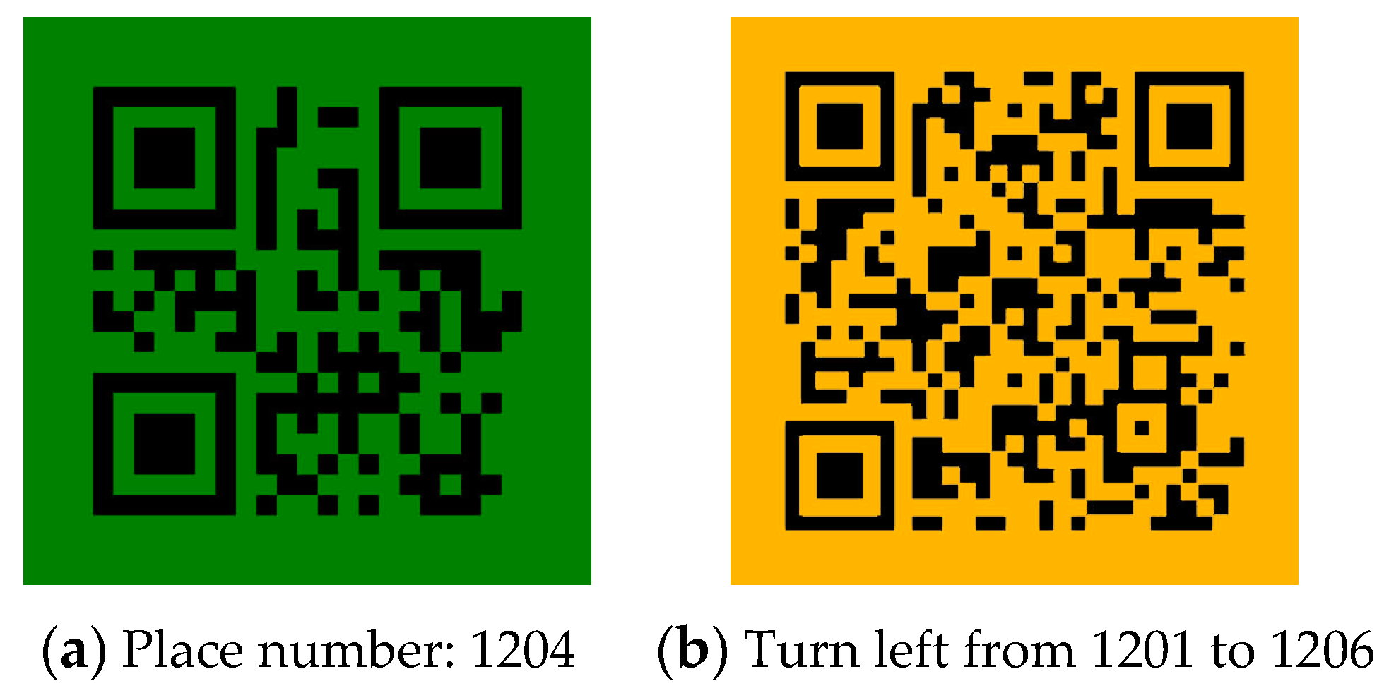
30]. Although a variety of color codes have been proposed, the QR code was chosen for the proposed system for several reasons. First, it can hold a large amount of information, including numerals, alphabet characters, symbols, and control codes. Second, the reader is freely available and can be installed on all smartphones with cameras, and it runs quickly and reliably. Accordingly, QR codes were used to represent the environmental information and then modified to increase their usability.
Unlike the existing methods that use QR codes to represent URLs [
44], we used QR codes to represent numerical and alphabetic characters that indicate the positioning information such as the room numbers and signs indicating stairs and exits. Therefore, no network access is required in order to interpret the meaning of the QR codes. In addition to facilitating easier discernment of the QR codes from the background, green and orange color were used to denote the QR code quiet zones. For the minimized modification in the environment, the QR code size was set to 12 × 12 cm
2, which was determined through experiments. The QR code was located 140 cm above the floor.
Based on the current situation, the proposed system detects different types of QR codes. The green QR codes are used to represent location-specific information, which are usually located next to the doors; the orange QR codes indicate directional information and appear in corridors, halls, and junctions. Because the standard green color (RGB (0, 255, 0)) and orange color (RGB (128, 128, 0)) in real environments appear similar to fluorescent green and orange with diffuse reflections, this study used a darker green color (RGB (0, 128, 0)) and a darker orange color (RGB (256, 186, 0)).
Figure 6 presents the examples of the generated QR codes and their meanings.
Figure 6a is a QR code that encodes the location-specific information: this room is 1204.
Figure 6b is a QR code that encodes directional information: Turn left from room 1201 to room 1206.
5.1. Object Detection
In the proposed system, the QR codes use dark green or dark orange to represent the quiet zones, and they have a square shape. Thus, they are detected by locating a green (and orange) square in a context. The process for detecting the QR codes is as follows:
- (1)
Preprocessing: Because time-varying illumination requires contrast adjustment, a histogram specification is used.
- (2)
Discretization: Each pixel in the input image is classified as green, orange or others. The color ranges are defined as follows:
- (3)
Labeling: Row-by-row labeling is performed on the discretized image. Then, the area and circularity are calculated from all components. These properties are used to remove noise: if the circularity of a region is larger than a predefined threshold or if its area is too small, it is considered to be noise. Thus, only components corresponding to color codes are filtered through this stage.
- (4)
Post-processing: After the noise filtering, the adjacent components are merged to prevent the color codes from being split.
Figure 7 shows the process used to localize the QR codes.
Figure 7a–c shows the input image, the discretized results, and the labeling. The detected regions of the QR codes are marked in red and blue; the red one indicates the detected location-specific code, and the blue one means the detected directional code, respectively. As shown in
Figure 7b, the discretized image includes abundant noise, which is removed using two geometric characteristics (see
Figure 7c).
5.2. Object Recognition
The code was attached to locations where real signage was placed in indoor environments. Once the code is localized in the detection module, the proposed system initiates the QR reader [
45]. A standard QR reader can accurately recognize the detected codes within a limited range as follows: the distance from the user to the codes should be within 1 m, and the code should be perpendicular to the user. Due to these limitations, after detecting the codes, the proposed system first measures the distance between the user and the detected code and the viewing angle between them. It then verifies if the two conditions are satisfied. If not, it guides the user to approach the code and adjust his/her position so that the QR reader can read the code. The details of this process are discussed in
Section 6.
6. User Interface with Activity-based Instructions
Recently, activity-based navigation has been proposed as an alternative to map-based navigation because it does not require a pre-installed map, and it is not dependent on absolute positioning [
34]. An activity denotes the mode of human movement such as standing, walking, climbing stairs or riding an elevator. Thus, activity-based navigation guides a user to a destination using a sequence of human movement activities such as walking a certain number of steps, going up or down, and so on. The efficiency of the method in reducing the mental burden on visually impaired people and reducing navigation errors has been demonstrated previously in [
34]. As mentioned above, people who go blind early and those born blind encode the sequential features of travelled route, i.e., a set of instructions that denotes the directional changes in their route. Therefore, activity-based navigation is well-suited to providing guidance information to these users.
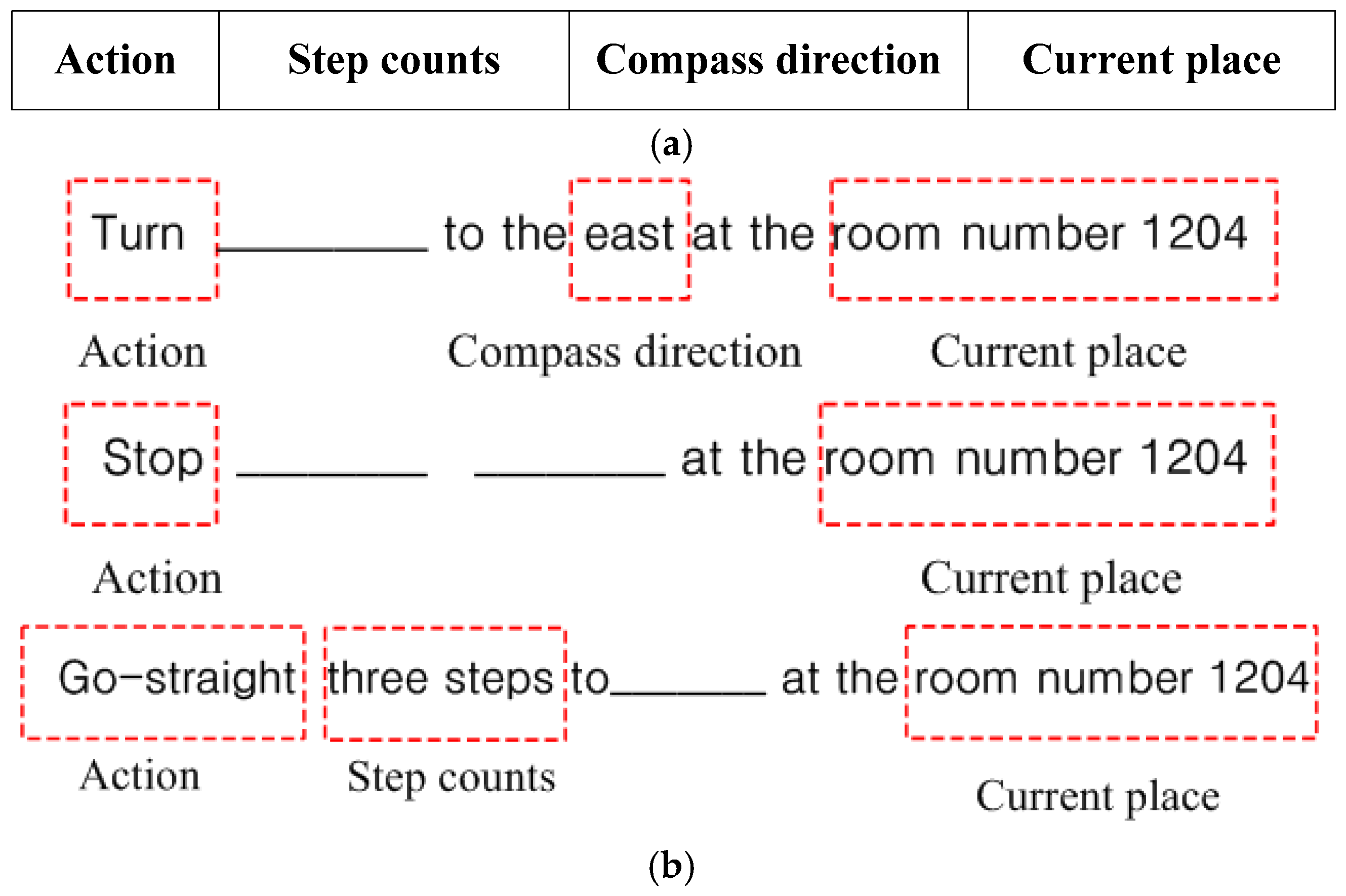
Accordingly, to convey the recognized results to users in a more efficient manner, new activity-based instructions were defined and used in the proposed system. Here, one instruction statement consists of four parameters: action, step counts, compass direction, and current place, which are shown in
Figure 8a. Based on the results obtained from the situation awareness and color code recognition modules, the user action is determined. Then, the parameters necessary for the required actions are calculated by analyzing the geometric characteristics of the detected QR code.
In addition, for the navigation system for blind users, the generated information is represented using spatial language (“turn left/right”, “go-straight,” or “stop”) or virtual sounds (i.e., the perceived azimuth of the sound indicates the target waypoint). The former is spoken to the user using a text-to-speech (TTS) service, and the latter is conveyed using beeps or sonar sounds. In the beginning of the wayfinding, spatial language is more effective for guidance to a specific direction or waypoint. However, when a cognitive load is present or accumulated while the user is moving, virtual sounds exhibited better performance than the spatial language [
37,
38,
39]. Therefore, the proposed method combined these approaches: for the actions of “go-straight” and “stop”, the number of step counts to the destination is important. Thus, the proposed system used beeping sounds with different frequencies according to the remaining number of step counts. However, for the action of ‘turn’, the proposed system uses spatial language to convey the directional command with compass directions through the text-to-speech service. The effectiveness of the combination of these two methods was demonstrated in a field study, which is described in
Section 8.2.3. Through field tests, the combined method exhibited better performance than using only speech-based spatial language.
6.1. Actions
In the proposed system, the possible actions are go straight, turn, and stop, each of which is determined according to several conditions such as the current situation, code detection, and viewing angle and distance between the user and the color codes. This determination process is summarized in
Table 3.
When color codes are not detected, the proposed system guides the user to continue to go straight along their original direction. However, if a color code is found, it verifies whether the QR code is placed within a recognizable scope. Then, if the two QR code-reading conditions are satisfied (as specified in
Section 5.2), it selects the appropriate action based on the current situation. For example, when a user is standing in a hall, junction, or corridor, it chooses the turn action (see the third row of
Table 3). However, when a user is standing in front of a door, the proposed system first verifies whether the current positioning is the destination and then directs the user to stop or return to the previous route to continue his/her travel.
After determining a suitable action according to the user’s conditions, the necessary parameters for performing the respective actions should be calculated. For a go straight action, a step count is necessary to approach the detected color code or the next location. For the turn action, the compass direction is required to guide the user’s orientation for the next direction. Then, when the destination is reached, the proposed system is terminated, and it waits until a new destination is given. Accordingly, the instructions are presented in three forms according to the action type and are shown in
Figure 8b.
6.2. Current Place
The positioning information is required for all actions. In this study, the positioning information is denoted by the current situation or current place. If explicit information is provided by decoding QR codes, the places are clearly denoted such as Room 1204, toilet, or other specific locations; otherwise, the situation such as a junction or hall is used to denote the current place. Such information is obtained through the situation awareness and object detection and recognition.
6.3. Compass Direction
Here, the compass direction is described by the cardinal direction, and the possible direction is selected from the following eight orientations: {north (0°), northeast (45°), east (90°), southeast (135°), south (180°), southwest (225°), west (270°), and northwest (315°)}. Sometimes, the compass direction is clarified explicitly by the QR codes that represent directional information (see
Figure 6b). However, in many cases, the compass direction is not clarified, e.g., when the detected color codes are not placed within a recognizable scope and when a user wants to return to the previous steps. To guide users in such cases, two algorithms were developed to calculate the compass direction. The first algorithm is a vision-based algorithm that was developed to calculate the compass direction based on the viewing angles between a user and the detected QR codes. The second algorithm is a sensor-based algorithm that calculates the compass direction using the difference between the user’s successive motions obtained from the gyroscope and accelerometer. In this section, only the vision-based algorithm is illustrated, and the sensor-based algorithm will be discussed in
Section 7.
To calculate the viewing angles between the user and QR codes, a regular 36 × 36 grid map was used, and each cell was 5 × 5. The procedure to estimate the viewing angle between the camera and color code is as follows:
- 1)
The regular grid map is overlaid on the detected color code.
- 2)
For the cells allocated on both sides, the densities of the green-colored cells on the Y-axis are accumulated; each cell is denoted as DL or DR, respectively.
- 3)
The direction of the left or right side is set by the sign of the difference between the two accumulated densities.
- 4)
The viewing angle is determined by the difference between the two accumulated densities, i.e., |DL-DR|.
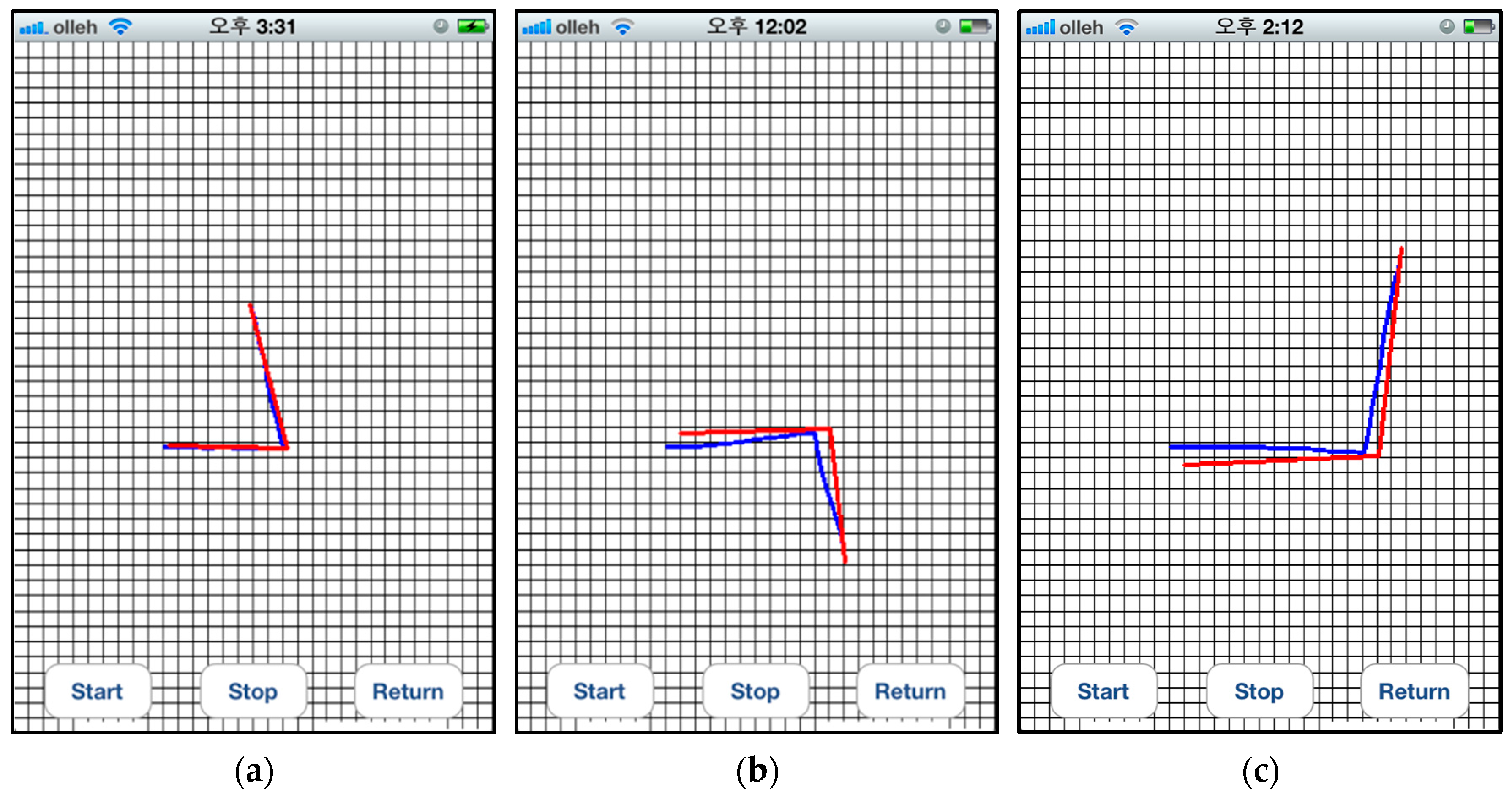
Figure 9 shows that the different values as the viewing angles increase at various distances. As can be seen in this figure, these differences are directly proportional to the viewing angle between the user and the color code, that is, the difference gradually increases with larger viewing angles.
6.4. Step Counts
A step count is obtained by dividing the distance to a specific position by a normal step distance. Here, a normal step distance is assumed to be 0.5 m. When QR codes are not detected and when a user is turning, the step count is fixed to 3 because the proposed system can detect objects at a distance of 2.5 m from a user. In other cases, the distance is calculated using image processing. The step count calculation is performed after estimating the viewing angle because the distance measured at the perpendicular line from the color codes is more accurate.
Similar to the calculation for the compass direction, the regular grid map is first overlaid on the codes. Then, the distance is obtained by counting the number of grid cells that are mapped to the green quiet zone. Its ratio over all cells is inversely proportional to the distance, that is, the ratio gradually decreases with larger distances between the user and the color code.
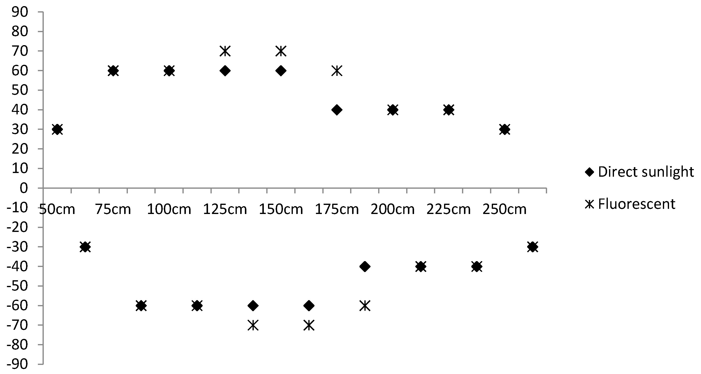
Figure 10 shows the color codes that are captured at several distances and viewing angles. The images in
Figure 10a,b were captured from the same distance; however, they have different viewing angles of 20° and 50°, respectively. The images in
Figure 10c,d were captured at a distance of 0.5 m and 1.25 m, respectively, from the user.
To measure the viewing angles and distances from the user, the regular grid map was first overlain on the detected color codes shown in
Figure 10. Then, the difference was calculated between the densities of the green-colored pixels at both ends, and the ratio of green-colored cells over all cells was counted. As shown in
Figure 10, the difference in
Figure 10a is larger than that in
Figure 10b, and
Figure 10c has a smaller ratio than that of
Figure 10d.
7. User Trajectory Recording Module
When a user returns to his/her start point (i.e., lobby or elevator), it can cause a mental and physical burden on the user. To reduce his/her difficulties, we provide the back paths using the recorded paths. To do this, this module records a user’s trajectories until he/she arrives at his/her destination from the starting point to help him/her return to a previous location such as the starting point. Using the sensors that are already integrated into mobile phones, the paths can be constructed automatically while the user is moving. Here, two inertial sensors are used: a gyroscope and an accelerometer.
Algorithm 1 describes the algorithm used to record a user’s trajectory to the destination. All paths are recorded to the stack (S), and each path is formatted as one instruction statement. Thus, the action should be defined first, and then, the related parameters, e.g., step counts (SC), compass direction (
), and current position (P), should be estimated. In this module, these parameters are calculated based on the sensory information.
| Algorithm 1: The proposed trajectory recording algorithm. |
| Input: Gyroscope sensor G, Accelerometer sensor AC, destination D |
| Output: Stack S that contains the set of instructions, I(A, SC, , where A, SC, , P are the variables for the action, step count, compass direction, and position, respectively. |
| Procedure: |
| 1. | Initialize A ← null, , , SC ← 0, P(, ) ← (0,0); |
2. | // Determine the action type
If AC < 0.03, then A ← Stop |
| 3. | else if then A ← Turn |
| 4. | else A ← Go-straight |
| 5. | //Estimate the instruction parameters according to the action type
if A is Go-straight, then SC, , is updated by the following equation:
|
| 6. | else if A is Turn, then |
| 7. | PushI(A, SC, to S |
8. | //check if the current positioning information is the destination (the positioning information is obtained by recognizing the QR codes)
if the current location is destination, then terminate |
| 9. | else Go to Line 2 |
Once the user arrives at the destination, the return route to the origin should be provided. The algorithm used to provide the reverse path is simple and described in Algorithm 2. As shown in Algorithm 2, the instruction that is placed on the top of the stack is conveyed to the user. Because the main users of the proposed system are blind or visually impaired, all instructions are provided verbally through text-to-speech functionality.
| Algorithm 2: The proposed trace backward algorithm. |
| Input: Stack S that contains the set of instructions, I(A, SC, ), where A, SC, , P are the variables for the action, step count, compass direction, and position, respectively |
| Output: Instruction |
| Procedure: |
| 1. | Pop I(A, SC, from S |
| 2. | if A is Turn, then ← . |
3.
4.
5.
6.
7. | //Generate the instruction statement according to the action type
if A is Go-straight, Pop I(A, SC, from S
if A is Go-straight, then
else, Push I(A, SC, to S and make instruction as ‘Go-straight SC steps’
else if A is Turn, then make instruction as ‘Turn to the
else make instruction as ‘Stop’
//Convey the instruction to the user, through Text-to-Speech (TTS) service |
| 8. | Call TTS (instruction) |
| 9. | if S is empty, then terminate |
| 10. | else Go to Line 1 |
9. Conclusions
This study developed a new situation-based wayfinding system to help blind and visually impaired users recognize their location and find their way to a given destination in an unfamiliar indoor environment. The proposed wayfinding system was implemented on an iPhone 6, and it consists of five modules: situation awareness, object detection, object recognition, activity-based instruction, and user trajectory recording.
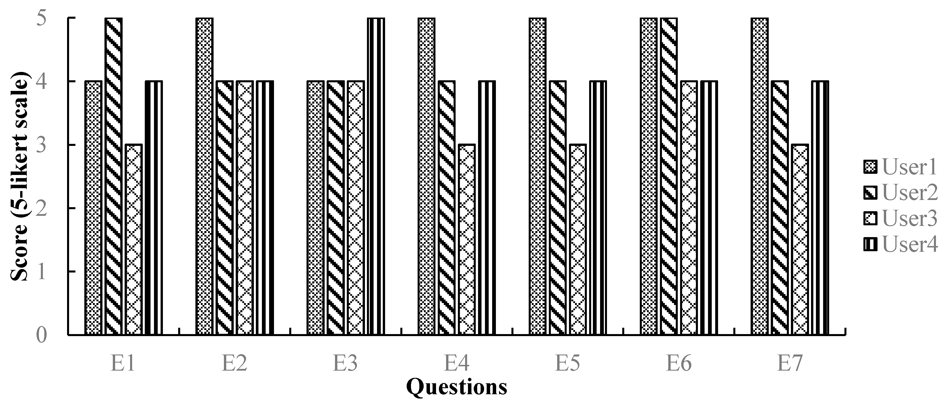
To assess the validity of the proposed codes and wayfinding system, experiments were conducted in several indoor environments. The results show that the proposed system could detect the color codes with an accuracy of almost 100% at a distance of 2.5 m and a viewing angle of ±40°, while recognizing their meaning with an accuracy of above 99%. In addition, to confirm its real-time efficacy, field tests were performed with four users who have significant visual impairments; all the users found the optimal path in real-time with an accuracy of 97%.
A significant contribution of the proposed system over existing systems is that it does not rely on prior knowledge such as maps or 3D models of buildings by automatically predicting the outline of the buildings through situation awareness and scene object recognition. Another contribution is the development of a wayfinding system for mobile phones that are equipped with a camera and inertial sensors (i.e., gyroscope and accelerometer), which can guide users along a route to the target destination. A third significant contribution is that the proposed system has a more efficient user interface using activity-based instructions.
The proposed system needs some improvements including (1) the provision of optimal path guidance to users through combining map information with the proposed system [
16,
35], (2) increases in the localization accuracy through integrating the UWB technique in cluttered environments [
17], and (3) verification of the generalizability of the proposed system through designing various scenarios with more varied users.
In order to fully support the mobility of blind people and visually impaired people, a system that can prevent collisions with obstacles should be incorporated into the current wayfinding system, and intensive formal validation tests should be performed with more users in order to generalize the system’s efficiency and validity. In this area of research, the previous studies of the author developed an intelligent wheelchair [
48,
49] and EYECANE [
50,
51]. The intelligent wheelchair was used for severely disabled people and it provides anti-collision maneuvers as well as a convenient user interface. EYECANE is a camera-embedded white cane that detects obstacles and find obstacle-less paths using a vision-based technique. To avoid obstacles in a more efficient manner, situation information is required, e.g., users should walk along a corridor wall, they should stop in front of a door, and so on. Thus, in future research, a technique to avoid obstacles will be developed based on situation information, and algorithms will be integrated into EYECANE. The current wayfinding system will be combined with the extended EYECANE to support safer mobility of blind and visually impaired people.


