1. Introduction
The ankle joint plays a key role in maintaining balance during walking [
1,
2,
3]. Recently, there have been an increasing number of people suffering from ankle injuries caused by diseases and accidents. In the US, more than 23,000 cases of ankle sprain injuries happen every day [
4]. The postoperative recovery from ankle injury is slow and ineffective while the application of rehabilitation robots is supposed to be possible to solve this problem. Rehabilitation robots can help patients accomplish repetitive training tasks more accurately and effectively without physical therapists’ excessive participation [
5,
6,
7]. Increasing attention has been paid to the robotic rehabilitation that is appropriate to perform repetitive exercises for the recovery from neuromuscular injuries [
8].
In the perspective of ankle rehabilitation, parallel robots can produce greater torque as well as achieve multiple movement degrees of freedom (DOFs) [
9]. A series of parallel platform-based ankle rehabilitation robots have been developed [
10]. Liu et al. [
11], Alireza et al. [
12], and Mozafar et al. [
13] all proposed a 6-DOF ankle rehabilitation robot based on the Stewart platform. However, these robots utilized rigid actuators, such as electric motors or cylinders [
14] that cannot achieve soft and compliant interaction with the patients. To overcome the limitations, some researchers started to use pneumatic muscles (PMs) as actuators to drive the ankle rehabilitation robot. PMs have inner compliance, high power/weight ratio [
15] and can drive the robot in a safer way, so they have become increasingly popular in the rehabilitation robots [
16]. Xie et al. [
17,
18] designed a four PMs-driven 3-DOF ankle rehabilitation robot with large workspace and good flexibility. Park et al. [
19] in Harvard University designed a PMs-driven ankle rehabilitation robot by simulating the human muscle-tendon-ligament model, in which the PMs directly drove the foot to complete dorsiflexion/plantarflexion and inversion/eversion movements. Sawicki et al. [
20] also used multiple PMs to provide dorsiflexion and plantar flexion torque for the ankle movement. Patrick et al. [
21] designed a 2-DOFs ankle rehabilitation robot driven by three PMs to help patients achieve plantarflexion/dorsiflexion and inversion/eversion movements.
PMs have strong non-linearity and time-varying properties [
22], which may cause difficulties in implementing precise control [
23]. In order to solve these problems, a variety of control approaches have been developed. Zhao et al. [
24] used neural network to adjust the parameters of PID controller. However, the method has the problems of long response time, poor tracking on desired trajectory and low tracking accuracy in the step response experiment. Zhang et al. [
25] proposed a hybrid fuzzy controller to control the elbow exoskeleton robot actuated by PMs. However, this method cannot estimate the external disturbance when chattering happens, resulting in a large overshoot of step response. For the safety of human-robot interaction, Choi et al. [
26] proposed a new approach to control the compliance and associated position independently. However, when an external disturbance occurs suddenly, the control method cannot detect the external disturbance quickly and it takes a long time to re-track the desired trajectory. Meng et al. [
9] proposed an iterative feedback tuning control method for the repetitive training. However, the actual trajectory changed in a ladder shape because the external disturbance cannot be estimated. Jiang et al. also [
27] proposed an adaptive fuzzy control algorithm based on neural network optimization to control the humanoid lower limb device driven by pneumatic muscles. However, this method cannot achieve high-accuracy tracking control and the error would significantly increase when the external load changes.
During the operation of rehabilitation robot, external disturbances are usually inevitable [
28]. To obtain good control performance, the applied disturbance needs to be known exactly. However, external disturbances are often difficult to get accurately [
29]. Therefore, one of the reasons why the above control method cannot achieve better control accuracy is that the external disturbance cannot be estimated. It has been recently accepted that the disturbance observer is a good choice to solve this problem [
30]. Yang et al. [
31] designed an error-feedback controller based on extended state observer to estimate the external disturbances and improve the trajectory tracking accuracy of a PMs-driven robot. Zhu et al. [
32] presented an adaptive robust controller based on a pressure observer to control a three PMs-driven robot without pressure sensors. Wu et al. [
33] proposed a novel nonlinear disturbance observer-based dynamic surface control (NDOBDSC) and can solve the friction and unknown external disturbances existing in the PM-driven device. Youssif et al. [
34] designed a nonlinear disturbance observer (NDO) to estimate the lumped disturbance. Zhang et al. [
35] proposed an active disturbance rejection controller for a PM actuator to achieve angle tracking precisely under varying load conditions. Plenty of studies have implied that external disturbance observer can reduce the error and improve the control accuracy effectively.
On the other hand, since the parallel robot actuated by PMs is a complex high-order nonlinear system, it would be increasingly difficult to develop an accurate control scheme for the system [
36]. The backstepping sliding mode control (BS-SMC) can decompose a high-order nonlinear system into several lower order subsystems and design an intermediate virtual controller for each subsystem, which can improve the control performance [
37]. In recent years, BS-SMC has attracted the interest of many researchers. Petit et al. [
38] used backstepping sliding mode method to control a robot with variable stiffness and achieved satisfactory tracking performance. However, the tracking error would obviously increase if external disturbance occurred. Taheri et al. [
39] designed a backstepping sliding mode controller for pneumatic cylinders suitable for wearable robots. The force and stiffness tracking performance were better than the previous pneumatic force-stiffness sliding mode controllers. However, the overshoot of this control scheme was still large and there was no experiment with variable loads. Esmaeili et al. [
40] used a backstepping sliding mode controller to achieve balancing and trajectory tracking of Two Wheeled Balancing Mobile Robots (TWBMRs).
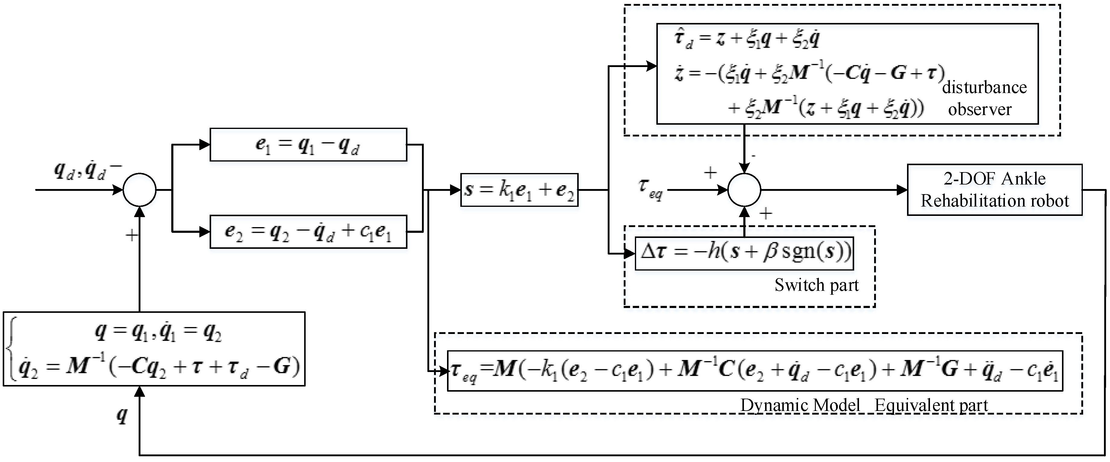
As concluded from the previous studies, there will be excessive overshoots or significantly increased errors when the external disturbance happens. The main reason is that the above methods cannot estimate the external disturbance, and as a result the control output cannot be adjusted in real time. This paper will propose an adaptive backstepping sliding mode control (ABS-SMC) with the capacity to estimate the external disturbance during operation, thus improving the robustness and accuracy of the control method. The ABS-SMC method is applied to a new 2-DOF parallel ankle rehabilitation robot which has been recently developed by us using pneumatic muscles. The controller can also deal with the nonlinearities and uncertainties of the robot system. The rest of this paper is arranged as follows:
Section 2 presents mechanism design of the ankle robot. The control strategy is described in
Section 3. In
Section 4, experiments are carried out to verify the performance of the controller.
Section 5 draws conclusion of the paper.
2. The Ankle Rehabilitation Robot
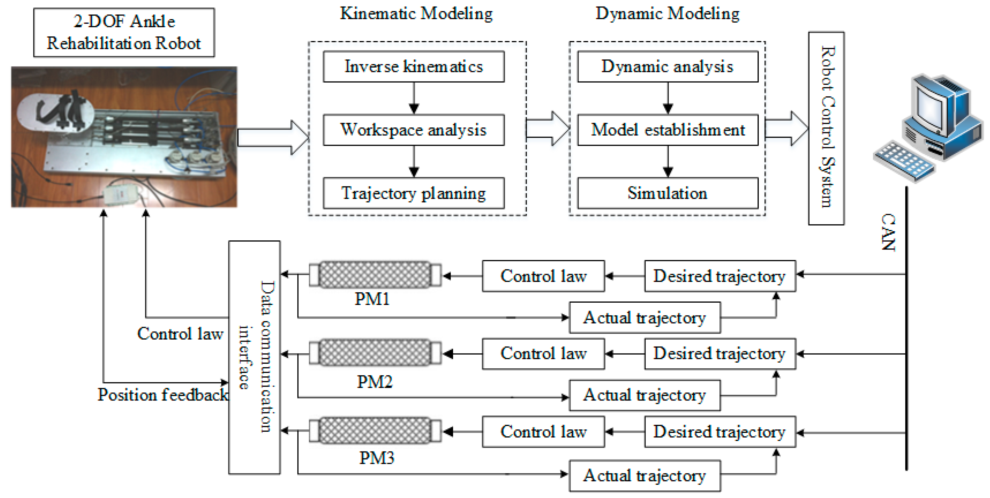
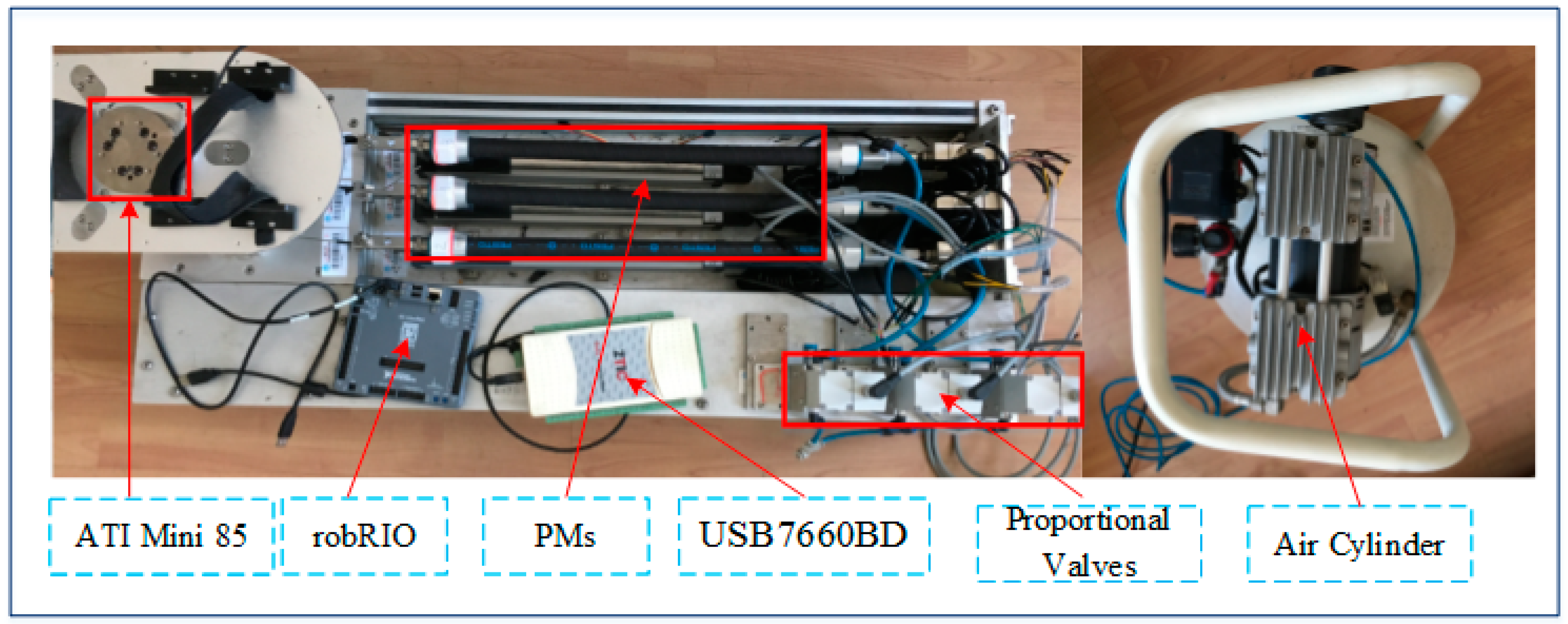
The complete system of the 2-DOF ankle rehabilitation robot and its hardware configuration are shown in
Figure 1 and
Figure 2, respectively. The robot consists of a fixed platform, a moving platform, and three pneumatic muscle actuators. The moving platform is equipped with two angle sensors (GONIOMETER SG110) to measure its real-time orientation angle around the X and Y axis. Each pneumatic muscle (FESTO MAS-20-400N) is controlled by an air pressure proportional valve (ITV 2050-212N). The position information of each pneumatic muscle is collected by displacement transducers (MLO-POT-225-TLF). A force/toque sensor (ATI Mini85) is mounted between the platform and the footplate to measure the applied ankle torque. Through the data acquisition card, the sensing data are gathered by robRIO and then transmitted to the host computer. After the D/A conversion of the data, the control signals are input to the corresponding proportional valves to control pneumatic muscles, thus driving the upper platform to move. The ABS-SMC is implemented in the host computer and closed-loop control is realized on LabVIEW.
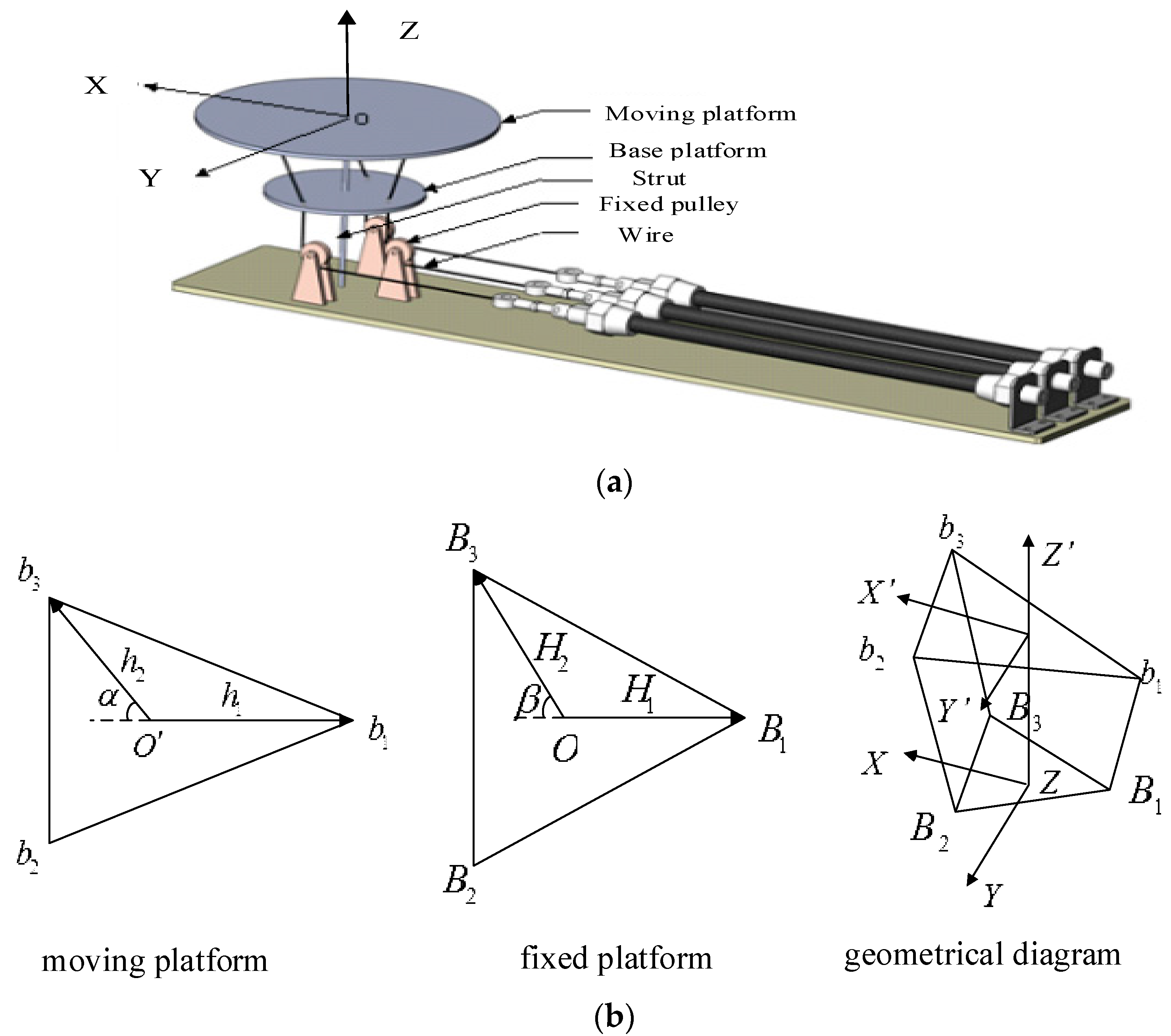
Figure 3a,b show the simplified structure and geometrical model of the designed ankle rehabilitation robot. Since the PM can only provide pulling force, the robot must have a redundant actuation mechanism [
41]. So the 2-DOF ankle rehabilitation robot is actuated by three pneumatic muscles. The lower fixed platform has three fixed holes, and the wires pass through the holes on the fixed platform. A strut is fixed between the fixed platform and the moving platform (end-effector). The Hooke joints between these two platforms guarantee that the robot can only move at two orientations. When the muscles’ lengths change, the platform can be controlled to work on two orientations. In order to reduce the height of the robot and make it easier for human usage, three PMs are placed in the horizontal direction, using three fixed pulleys to change the direction of actuating forces. In this case, the overall height of the robot is only 0.3 m.
In order to control the robot end-effector to track a predefined trajectory for ankle movement training, the robot kinematic model must be studied [
42], using which the joint space displacements can be determined from the end-effector orientation. As shown in
Figure 3b,
and
represent the moving platform and the fixed platform, respectively. The vectors that connect the moving platform and the fixed platform can be written as
,
and
.
and
are coordinate system of the moving platform and the fixed platform, respectively. A space vector in the moving coordinate can be transformed to the fixed via rotation matrix, which is widely used to establish inverse kinematics of the parallel rehabilitation robot [
43]. Here
,
,
,
,
,
. The rotation matrix can be expressed as:
The solution of
,
and
is necessary for robot control and workspace analysis. It can be obtained by using the inverse kinematics. The link’s length of this parallel robot is:
where
is the vector from
to
,
is the vector from
to
,
is the vector from
to
and
is the vector from
to
.
The dynamic model of the robot describes the relationship between the output torque and the desired angle as well as angular velocity [
44]. The dynamics model is also the foundation of sliding mode control [
45]. Define
as the generalized coordinates of the robot’s moving platform, thus the generalized speed of the moving platform is shown in Equation (3).
Lagrange’s equation is suitable for the complete system and it can solve the complex system dynamic equation in a simpler way [
46]. So we use the Lagrange’s equation to establish the dynamic equation of the moving platform:
where
,
and
represent the robot inertia matrix, the Coriolis centrifugal force matrix and the gravity matrix,
is the robot torque and
is the external disturbance torque.
is mainly composed of human applied torque and the friction. The parameters in Equation (4):
where
is the mass of the moving platform,
is the rotational inertia of the moving platform,
is the position vector of the moving platform centroid,
and
is the spiral matrix of
. According to the formula, the driving force of each pneumatic muscle can be obtained, and finally to realize the accurate trajectory tracking of the robot platform.
5. Conclusions
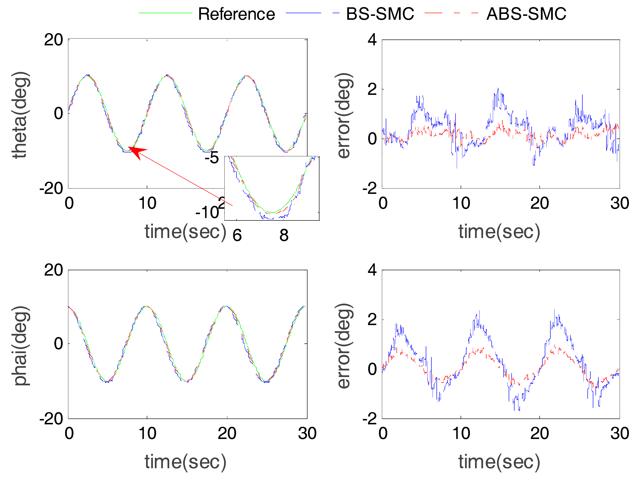
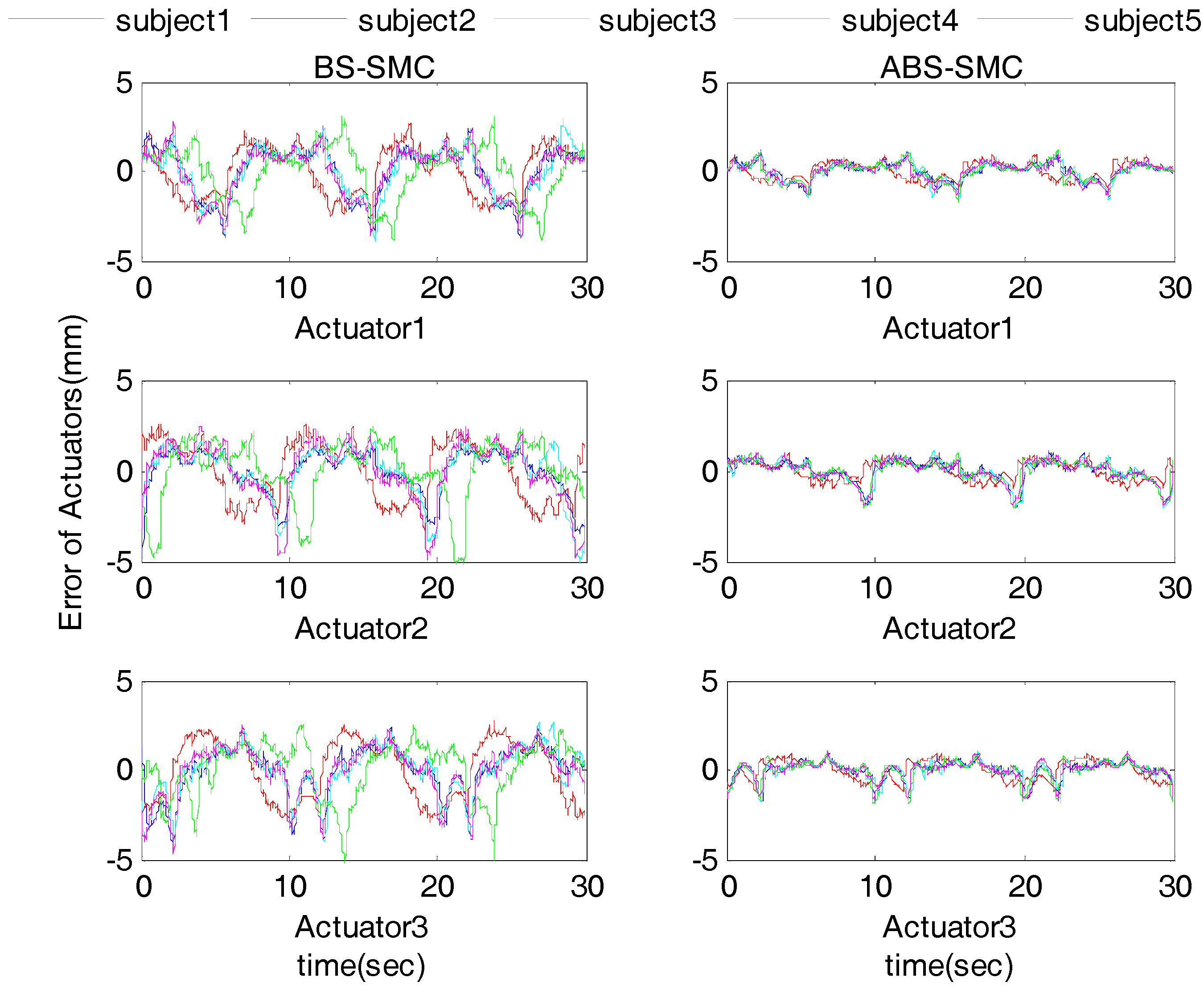
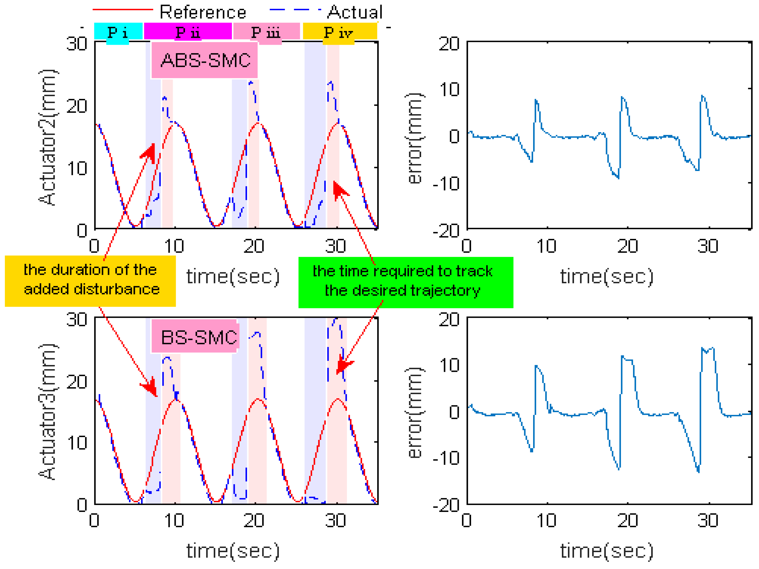
In this paper, a 2-DOF parallel robot was developed for ankle rehabilitation and the inverse kinematics model as well as the dynamics model of the robot were constructed. This paper proposed an ABS-SMC for PMs by introducing a disturbance observer, so the external disturbances can be estimated and the control output can be adjusted in real time. Experimental results show that the ABS-SMC had better trajectory tracking performance compared with the conventional method. The proposed method can greatly reduce chattering, which may reduce secondary damage to the patient. When participants were involved, the tracking error of traditional method obviously increased while the error of the proposed method remained small. In addition, the ABS-SMC has a better anti-interference ability. When the ankle rehabilitation robot was applied with greater resistance, the proposed method could quickly track the desired trajectory after removing the resistance. How the control would perform under uncertainties in the model and the applied torque is also need to be studied in the future. Because of the complexity of the ankle rehabilitation robot, it is difficult to establish a precise dynamic model. Our model here can match the real system to a large extent, which can also be reflected from the experimental results. However, the model uncertainties should be optimized further and the applied torque can be measured in real time by using a force/torque sensor to reach a more accurate model that will in turn improve the control performance. To improve the patient’s participation in the future work, patient force feedback must be considered. In this case, the performance of current position/force hybrid control and impedance control can be improved by incorporating the proposed ABS-SMC method. Furthermore, functional electrical stimulation, and biological signals should also be applied to the control of the robot to improve the patient’s voluntary participation and rehabilitation training performance.

 ,
, 


