3.1. Experimental Setup
An experimental setup was built to evaluate and compare the accuracy of the HCI, the LMC
® and the Intel RealSense
® SR300 (Intel Corporation, Santa Clara, CA, USA) [
40] in the hand tracking of the FT, OC and PS movements. The comparisons were made by using a DX400 optoelectronic system (BTSBioengineering, Milan, Italy) as gold reference (BTS SMART DX400©, 8 TVC, 100–300 fps) [
41].
The LMC hand-tracking device [
22] is built around two monochromatic IR cameras and three infrared LEDs, which project patternless IR light in a hemispherical working volume. The IR cameras reliably acquire images of the objects (hands) from 2 cm to 60 cm distance in the working volume, at a frame rate of up to 200 fps. To reduce possible interference among the several Infrared Radiation (IR) light sources of the different devices, the comparison was split into two experiments (
Section 3.1.1 and
Section 3.1.2): in the first one, the HCI, the LMC and the DX400 were involved; in the second one, the HCI, the RealSense SR300 and the DX400 were involved. In both the experiments, the devices’ accuracies were evaluated by comparison of the movements captured at the same time by the two devices with the DX400 reference system. It should be noted that we compared two SR300 devices; one is a component of the HCI of our system, and the other is an external device whose proprietary hand tracking firmware was to be assessed. In this case, we compared the performance of our tracking software, based on the processing of color and depth map of the SR300 implementing the HCI, with the proprietary one of the external SR300.
The movements were performed in the smallest working volume common to all the devices. Specifically, both the LMC and the SR300 used in the HCI have a working volume delimited by a truncated pyramid boundary, whose apex is centered on the device and whose top and base distances are defined by the reliable operating range. This range is established according to the device specifications [
22,
40] and the results of other experimental works [
29,
35], also taking into account a minimum clearance during movements, to avoid collisions. Consequently, we assume a reliable operating range for the LMC controller from 5 to 50 cm, while that of SR300 of the HCI can be safely reduced respect to the device specifications (20 to 120 cm) from 20 to 100 cm, considering the minimum spatial resolution necessary to track the colored marker at the maximum range. Therefore, the reliable working volume for the LMC is about 0.08 m
3, while that of the HCI is about 0.45 m
3, which is about six times bigger. Then, the smallest working volume common to all the devices is constrained by the LMC one, and therefore the accuracy evaluations and comparisons are limited to this volume.
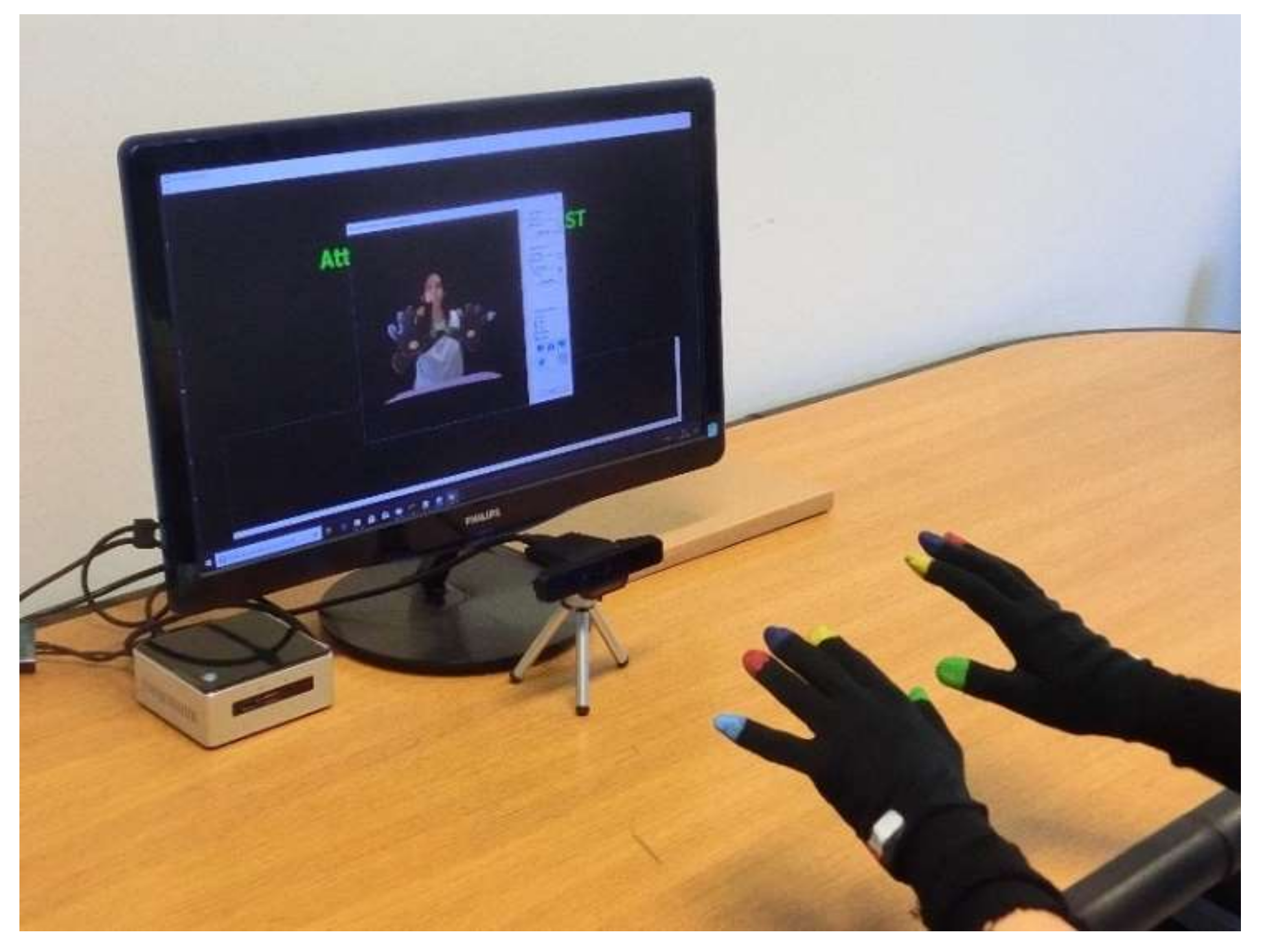
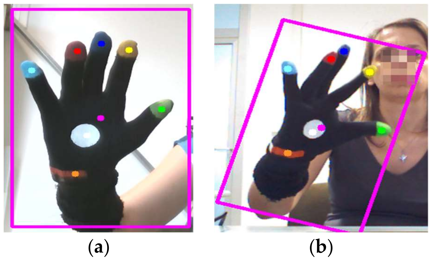
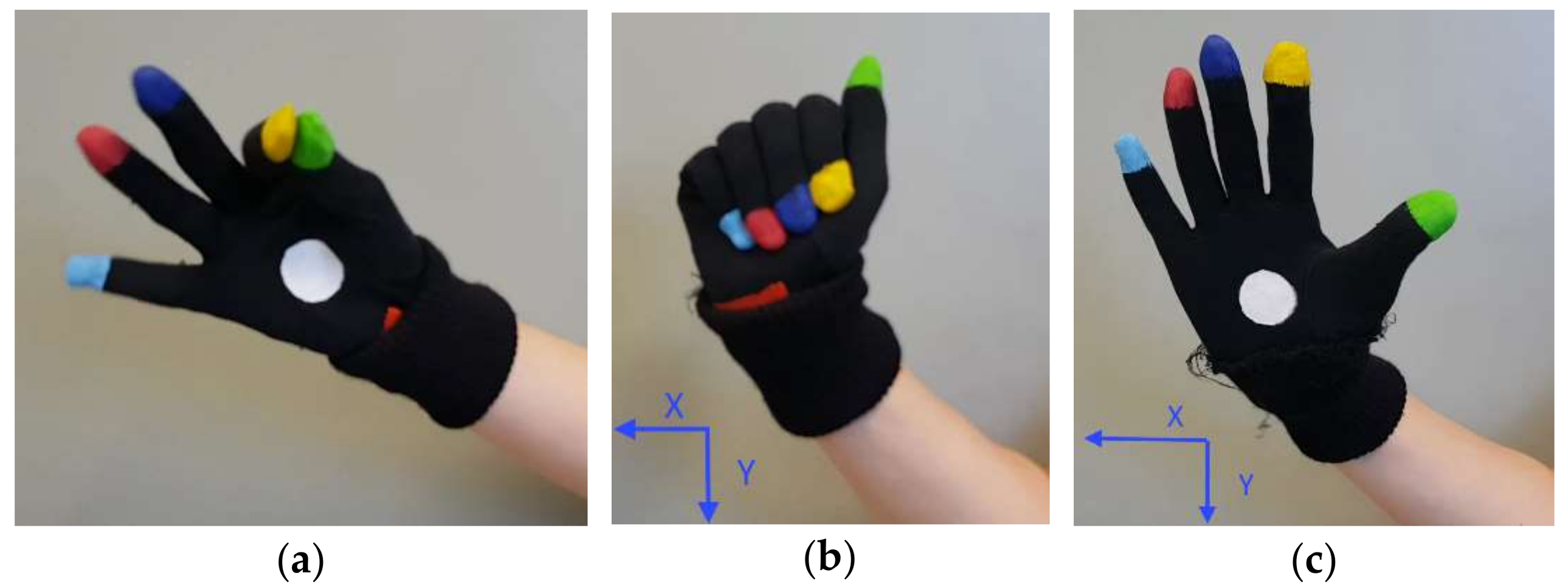
In the two experiments, five healthy subjects (3 men/2 women) of different heights (from 1.50 to 1.90 m), aged between 25 and 65, were recruited to assess the accuracy of the devices in hand tracking of FT, OC and PS movements. The subjects had no history of neurological, motor and cognitive disorders. The rationale of this choice is to provide a data set of finger trajectories approximately filling the working volume, which are representative both of the specific movements and of the population variability. Moreover, we chose healthy subjects because their movements are faster and of greater amplitude with respect to motor-impaired PD subjects, and therefore they are more challenging for accuracy evaluations. During the experiments, the subjects were seated on a chair facing the HCI and the LMC (or the SR300, in the second experiment), with the chest just beyond the upper range of the working volume. A set of hemispherical retroreflective markers, with diameter of 6 mm, were attached on the fingertips of the subject wearing the HCI glove (
Figure 4).
The subjects were told to perform the FT, OC and PS movements as fast and fully as prescribed in UPDRS guidelines [
2], with the hand in front of the devices. The movements were performed in different positions, approximately corresponding to the corners and the center of the bounding box of the working volume, with the aid and the supervision of a technician. A total of nine hand positions were sampled in the working volume. The movements were first performed by the right hand in its working volume, then by the left one, after adjusting the chair and subject position to fit its corresponding working volume. The 3D trajectories of the fingers were tracked simultaneously by the HCI and by one of the other two devices, and were then compared with those captured by the DX400 optoelectronic system.
The different 3D positions of the reflective and colored fingertip markers correspond to a 3D displacement vector with constant norm of about 9 mm between their respective 3D centers. This vector was added to the 3D centers of the colored fingertip markers to estimate the “offset free” colored marker trajectory, which was used for the HCI accuracy estimation. To evaluate the influence of the gloves respect to the bare hand on the commercial system accuracy, we performed two preliminary tests. First, we compared the luminance of the IR images of both the bare hand and gloved one, as obtained from the SDKs of the two devices. Please note that, IR images are used as input for the proprietary hand tracking firmware of the LMC. We found no substantial differences between the IR images of the hand in the two cases; neither in the spatial distribution, nor in the intensity of the luminance. Second, as in [
29], we compared the fingertip position of a plastic-arm model, fixed on a stand, in different static locations inside the working volume. In every location, we first put on and then removed the glove from the hand, looking at the differences in the 3D fingertip positions for the two conditions. Since we found position differences below 5 mm, we assumed the glove influence to be approximately negligible.
In both the experiments, we checked for possible IR interference among different devices by switching them on and off in all possible combinations, while keeping the hand steady in various positions around the working volume and looking at possible data missing or variations of tracked positions. A safe working zone of approximately 2 × 2 × 2 m in size was found, where the different devices were not influenced by one another. The devices could almost frontally track the hand movement, without line of sight occlusions. In the safe working volume, the claimed accuracy of the DX400 is 0.3 mm, and all markers were seen, at all times, by at least six of the eight cameras placed in a circular layout and few meters around the working zone. Two calibration procedures were used in the two experiments to estimate the coordinate transformation matrices for the alignment of the local coordinate systems of the different devices to the reference coordinate system of the DX400 (
Section 3.1.1 and
Section 3.1.2).
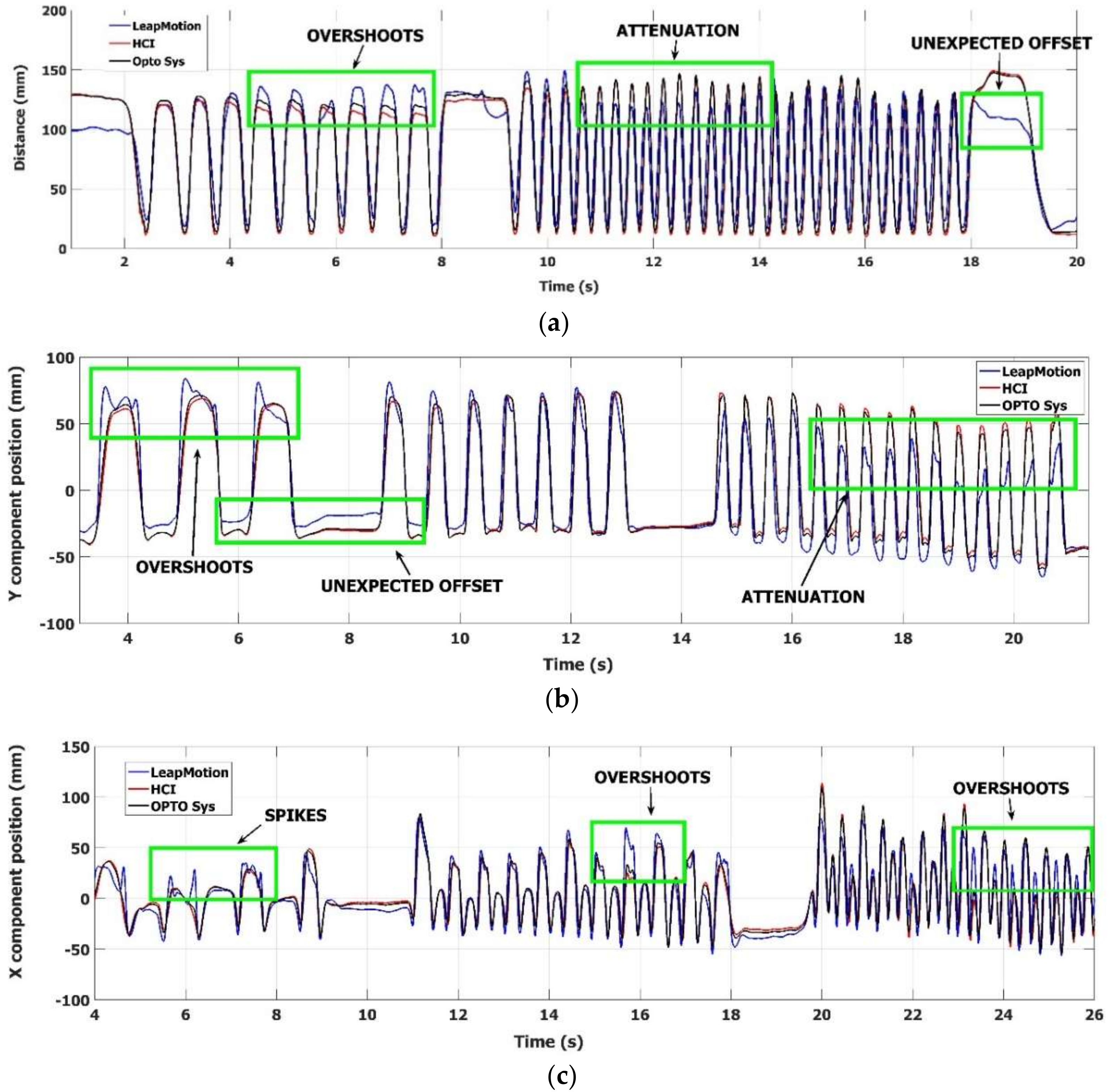
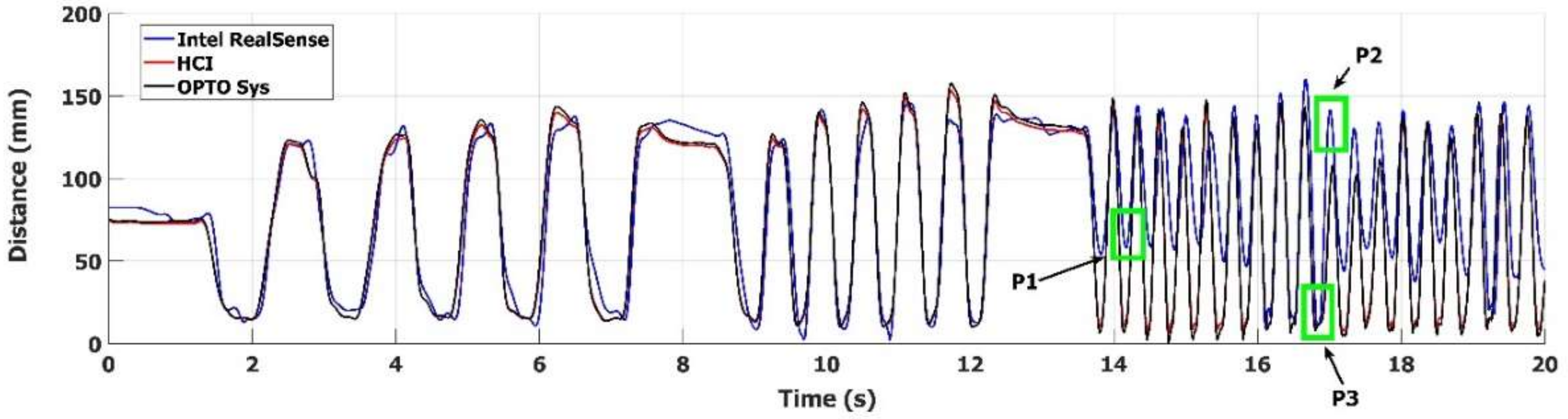
The devices have different sampling frequencies: a fixed sampling rate of 100 sample per second for the DX400, an almost stable sampling rate of 60 sample per second for the SR300, and a variable sampling rate, which cannot be set by the user, for the LMC, ranging from 50 to 115 samples per second in our experiments. Consequently, the 3D trajectory data were recorded and resampled by cubic spline interpolation at 100 samples per second to compare the different 3D measures at the same time. To compare the accuracy of the different tracking devices, we used the simple metrics developed in [
37], which provides a framework for the comparison of different computer vision tracking systems (such as the devices under assessment) on benchmark data sets. With respect to [
31], where the standard Bland-Altman analysis was conducted to assess the validity and limits of agreement for measures of specific kinematic parameters, we prefer to adopt the following more general approach and not to define, at this point, which kinematic parameters will be used to characterize the movements.
Consider two trajectories
X and
Y composed of 3D positions at a sequence of time steps
i. According to [
37], we use the Euclidean distance
di between two samples positions
xi and
yi at time step
i as a measure of the agreement between the two trajectories at time
i. The mean D
mean of these distances
di provides quantitative information about the overall difference between
X and
Y. Here we identify
X trajectory as measured by the DX400 reference system, and the distances
di can be interpreted as positional errors. Then, as in [
37], we adopt the mean D
MEAN, the standard deviation SD, and the maximum absolute difference MAD = |
di|
max of the
di sequence as useful statistics for describing the tracking accuracy. Furthermore, we note that, for the tracking accuracy evaluation of the FT, OC and PS movements, the absolute positional error in the working volume is not important; the correctly performed hand movements are necessarily circumscribed to a small bounding box positioned at the discretion of the subject in the working space.
On the other hand, we know the device measurements are subject to depth offsets increasing with the distance from the device [
33]. For this reason, some pairs of trajectories may be very similar, except for a constant difference in some spatial direction; that is, an average offset vector
(translation) could be present between the trajectories. Since this offset vector is not relevant for characterizing the movements, we subtract it from the
di sequence before evaluating the accuracy measures [
37], (p. 4). The accuracies were evaluated comparing the finger trajectories measured at the same time by one device and the corresponding one measured by the DX400. Only the trajectory parts falling in the working volume were considered in the comparison. The final measure of the device accuracy is obtained by the average values of the D
MEAN and the SD evaluated for all the trajectories captured by the device in the working volume, while for the MAD value the maximum over all the trajectories in working volume is considered.
Custom C++ scripts were developed for both the experiments to collect the data through the SDK APIs of the devices, and custom Matlab
® scripts (Mathworks Inc, Natick, MA, USA) were developed to perform the alignment of the finger trajectory data from different devices into the common reference frame of the DX400, and to evaluate accuracy measures (see
Table 1 and
Table 2).
3.1.1. Leap Motion and HCI Setup
The LMC was positioned facing the subject (the Y axis of the LMC reference system was pointing to the subject’s hand) at about 10 cm away from the closest distance of the hand in the working volume, and it was firmly attached on a support to avoid undesired movements of the device. The RGB-Depth sensor of the HCI was placed 10 cm beyond and above the LMC, to avoid direct interferences with the LMC and to allow the maximum overlapping of the working volumes of the two sensors.
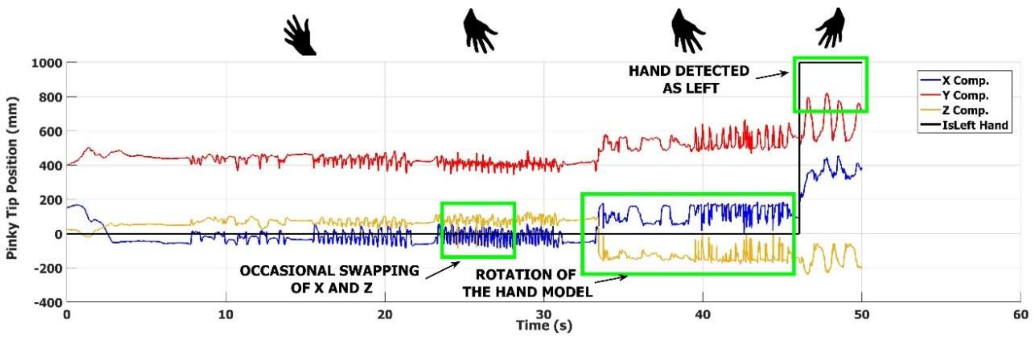
An external processing unit (Asus laptop Intel Core i7-8550U, 8 MB Cache) was used to run the scripts accessing the LMC proprietary software (LMC Motion SDK, Core Asset 4.1.1) for real-time data acquisition and logging. The final information provided by the scripts was the positions over time of 22 three-dimensional joints of a complex hand model, which includes fingertips. The LMC Visualizer software was used to monitor, in real time, the reliability of the acquisitions.
The calibration procedure, used to estimate the alignment transformation between the LMC controller and the DX400 coordinate frames, makes use of the same special V-shaped tool (
Figure 5a) as in [
29], which consists of two wooden sticks fixed on a support and two reflective markers fixed on the stick tips. The tool was moved around the working space and tracked both by the LMC and the DX400. The alignment transformation was estimated as the transformation (roto-translation) which best aligns the two set of tracking data by the two devices.
A different approach was used to estimate the alignment transformation between the coordinate frames of the SR300 device of the HCI and the DX400. A dihedral target, made of three planes orthogonal to each other, was built (
Figure 5b). Seven reflective markers were attached at its center and along the axis at a fixed distance from the origin. The depth maps of the SR300 device of the HCI were processed to extract the planes, and to estimate the dihedral plane intersections and their origin in the local coordinate system [
42]. The positions of the reflective marker on the plane intersections were measured by the DX400, in the global coordinate system. The alignment transformation was then estimated as the transformation which best aligns the two sets of data tracked by the two devices.
3.1.2. Intel SR300 and HCI Setup
We refer to
Section 2.1 for a brief description of the RealSense SR300 features. In this experiment, the Intel SR300 was positioned facing the subject at about 20 cm away from the closest distance of the hand in the working volume, and it was firmly attached on a support to avoid undesired movements. The device transmitted 3D position data of hand and fingertips to the Asus laptop PC (
Section 3.1.1) running specifically developed C++ scripts interfacing the SR300 SDK APIs [
23] for real-time data acquisition and logging. The same approach described in
Section 3.1.1 was used to estimate the alignment transformation between the coordinate frames of the SR300 device respect to the DX400. We note, as in
Section 3.1, that we compared two SR300 devices; one is a component of the HCI of our system, and the other is an external device whose proprietary hand tracking firmware was to be assessed.

 ,
, 


