Article

A Flexible Interdigital Electrode Used in Skin Penetration Promotion and Evaluation with Electroporation and Reverse Iontophoresis Synergistically

1
State Key Laboratory of Transducer Technology, Institute of Electronics, Chinese Academy of Sciences, Beijing 100080, China
2
University of Chinese Academy of Sciences, Beijing 100049, China
3
School of Public Health, Capital Medical University, Beijing 100069, China
4
Beijing Municipal Key Laboratory of Clinical Epidemiology, Beijing 100069, China
*
Author to whom correspondence should be addressed.
Sensors 2018, 18(5), 1431; https://doi.org/10.3390/s18051431
Submission received: 28 March 2018 / Revised: 25 April 2018 / Accepted: 2 May 2018 / Published: 4 May 2018
(This article belongs to the Section Biosensors)

Abstract

:
Skin penetration is related to efficiencies of drug delivery or ISF extraction. Normally, the macro-electrode is employed in skin permeability promotion and evaluation, which has the disadvantages of easily causing skin damage when using electroporation or reverse iontophoresis by alone; furthermore, it has large measurement error, low sensitivity, and difficulty in integration. To resolve these issues, this paper presents a flexible interdigital microelectrode for evaluating skin penetration by sensing impedance and a method of synergistical combination of electroporation and reverse iontophoresis to promote skin penetration. First, a flexible interdigital microelectrode was designed with a minimal configuration circuit of electroporation and reverse iontophoresis for future wearable application. Due to the variation of the skin impedance correlated with many factors, relative changes of it were recorded at the end of supply, different voltage, or constant current, times, and duration. It is found that the better results can be obtained by using electroporation for 5 min then reverse iontophoresis for 12 min. By synergistically using electroporation and reverse iontophoresis, the penetration of skin is promoted. The results tested in vivo suggest that the developed microelectrode can be applied to evaluate and promote the skin penetration and the designed method promises to leave the skin without damage. The electrode and the method may be beneficial for designing noninvasive glucose sensors.

1. Introduction

As traditional blood glucose testing is invasive, it brings great pain to the patient. However, diabetes patients need to measure glucose levels more than 8 times a day [1,2,3]. Thus, it also brings a big psychological burden to patients and could result in poor compliance. In recent years, researchers have used the ISF (interstitial-fluid) to replace blood for measuring human glucose concentration by a method of reverse iontophoresis extraction of ISF through the skin and achieved some results [4,5,6,7]. This method determines the blood glucose level based on monitoring the glucose concentration in ISF because a close relationship exists between the glucose concentration of the ISF and that of blood [8].
Due to the small volume of extracted ISF and the strong current density, reverse iontophoresis may damage skin. In addition, the measurement is inaccurate if the patient is moving, exercising, sweating, or experiencing rapid temperature changes [5,6]. When the extracted tissue fluid reaches a certain level, the glucose electrode can accurately test the results. As we know, the reverse iontophoresis applies a constant current to the skin. Under the action of the electric field, the positive and negative ions move in the subcutaneous tissue toward the cathode and anode respectively. The electric field of reverse iontophoresis forms a positive to negative ion current, which is used to carry the glucose in the subcutaneous tissue fluid to the skin surface [9]. The electroporation was firstly used for transdermal drug penetration, and it acts on the skin with a brief high-voltage pulse to achieve transient nanometer-wide aqueous pores in the formation of lipid bilayers in the skin, increasing the skin’s penetration during action [10]. There is a certain relationship between skin impedance and penetration. Under low frequency conditions (100 Hz~1000 Hz), skin impedance can better reflect its penetration. The smaller the impedance of skin becomes, the greater the penetration of skin becomes [11,12,13]. Traditionally, skin permeability evaluation, which is realized by impedance detected at a certain frequency based on macro-electrode, has the disadvantages of large measurement error, low sensitivity, and difficulty in integration [14,15]. Therefore, skin with a multilayer structure can be better characterized by its electrical properties using the interdigital microelectrode [16]. In the experiment, a low-cost flexible gold interdigital microelectrode is designed to evaluate skin penetration promotion by measuring skin impedance. The method of electroporation was used to open the water-containing channel to increase the penetration of the skin, and the reverse iontophoresis’s method was used to extract the glucose in the ISF. It is expected that the extraction time is shorter and current smaller, the extracted amount is larger. Synergistical combination of electroporation and reverse iontophoresis to achieve the expectation may be a way.
The objectives of this in vivo study are to evaluate and promote the skin penetration by interdigital microelectrode and to find suitable permeation-enhanced conditions through the designed method that can be used to guide ISF extraction, thereby providing guidance for blood glucose monitoring and diabetes management. In the study, different types of electroporation, various reverse iontophoresis and combination of electroporation and reverse iontophoresis for in vivo skin penetration experiments by interdigital microelectrode were applied and affected factors of these methods on skin penetration were explored, and noninvasive extracting glucose in the ISF was hoped for.

2. Materials and Methods

2.1. Fabrication of Flexible Gold Interdigital Microelectrode

The skin penetration promotion and evaluation was conducted with the same electrodes, which is designed with the form of a flexible gold interdigital microelectrode. The interdigital structure is one of the most commonly used form. It is often applied to the detection of multi-layer material properties because it can sensitively detect changes in material properties [17]. In this study, the design of the electrode was performed according to the literature [18]. Figure 1a shows the schematic of the flexible gold interdigital microelectrode multilayers. The gold interdigital detection layer (0.2 µm) is located on the top of the electrode. The material of the middle layer (12.5 µm) is polyimide. A copper shielding layer (0.2 µm) is formed on the bottom of the electrode, and the area of the shielding layer completely covers the corresponding area of the gold interdigital detection layer to reduce external interference. Figure 1b is the draft of interdigital electrode structure. “a”, “b”, “d” represent the left finger width, the right finger width and electrode spacing, respectively. The sizes/geometries of the electrodes were tested and validated to suit the impedance test of different individuals and different skin parts [19]. The optimum finger width parameter of the flexible gold interdigital microelectrode is a = 100 µm, b = 300 µm, d = 135 µm. Figure 1c is the multilayer sensors manufactured by HLDtech, Inc. (Beijing, China) based on flexible FPC technology.

2.2. Circuit Design of the Electroporation

High voltage is used in electroporation, but the actual voltage on the skin is relatively low. Chizmadzhev Y et al. (1997) believe that combining with the theory and experiment, this voltage can choose the moderate value Uskin = 10~60 V [20]. Therefore, the pulse voltage of electroporation was 0~60 V in this paper. The reduction of the voltage used for electroporation can greatly simplify the complexity of the circuit and enable miniaturization of the electroporation.
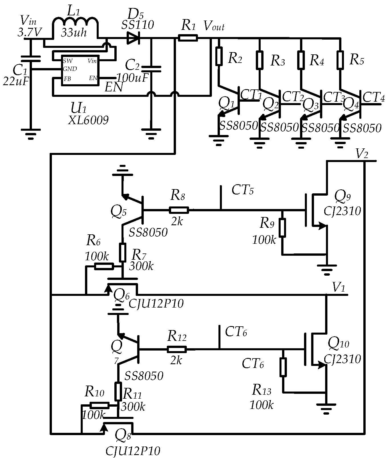
The circuit of electroporation consists of two parts, voltage regulation and output control circuit as shown in Figure 2. While the voltage regulation consists of an integrated circuit (U1), 2 capacitors (C1 to C2), 1 diodes (D1), a resistor (R2) and a series of variable resistors (R2 to R5) for an adjustable voltage. The U1 is a boost power supply module and it can boost a 0 V into 60 V. The output voltage is determined by the resistor R2~R5. Rx is controlled by a switch. When CTx is high, the corresponding switch turns on the response resistor and four different voltages can be achieved.
The output voltage can be derived using Equation (1):
V o u t = 1.25 × ( 1 + R 1 / R x )
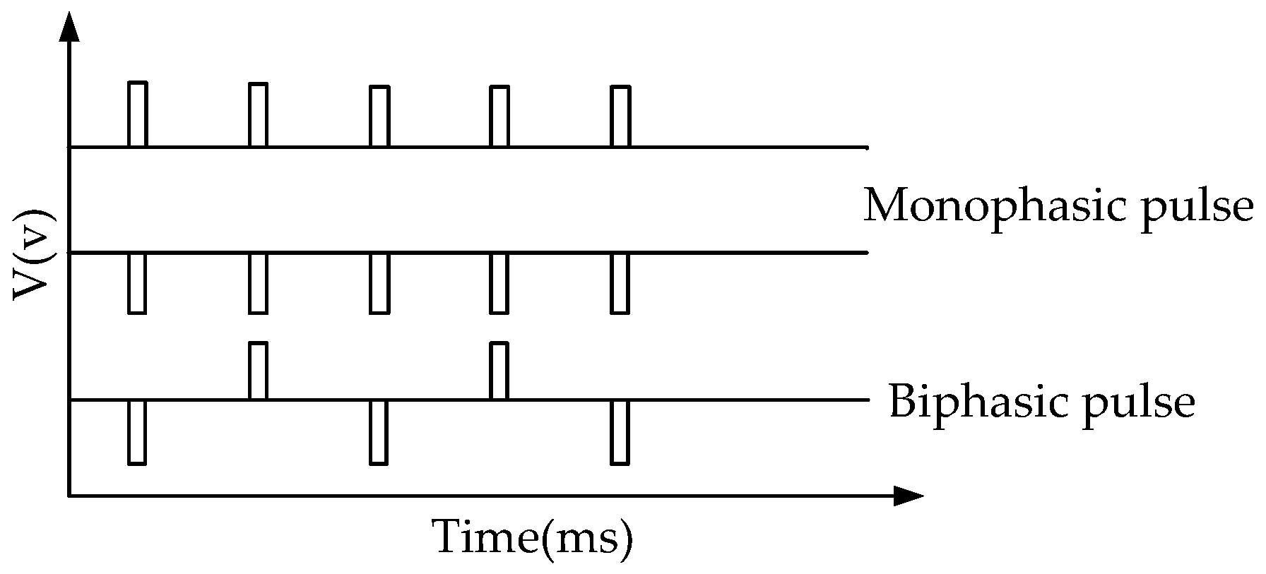
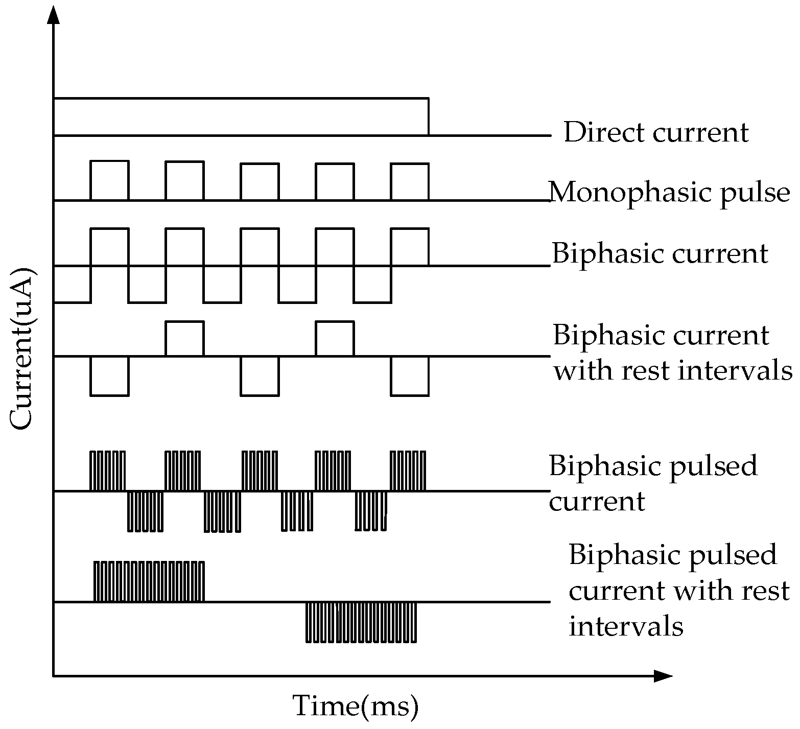
The combination of CT5 and CT6 controls can implement different types of pulses. When CT5 is high, Q6 and Q9 are on, and the positive pulse voltage is output. When CT6 is high, Q8 and Q10 are on, and the negative pulse voltage is output. When CT5 and CT6 are alternately high, a bidirectional pulse voltage is output.

2.3. Circuit Design of the Reverse Iontophoresis

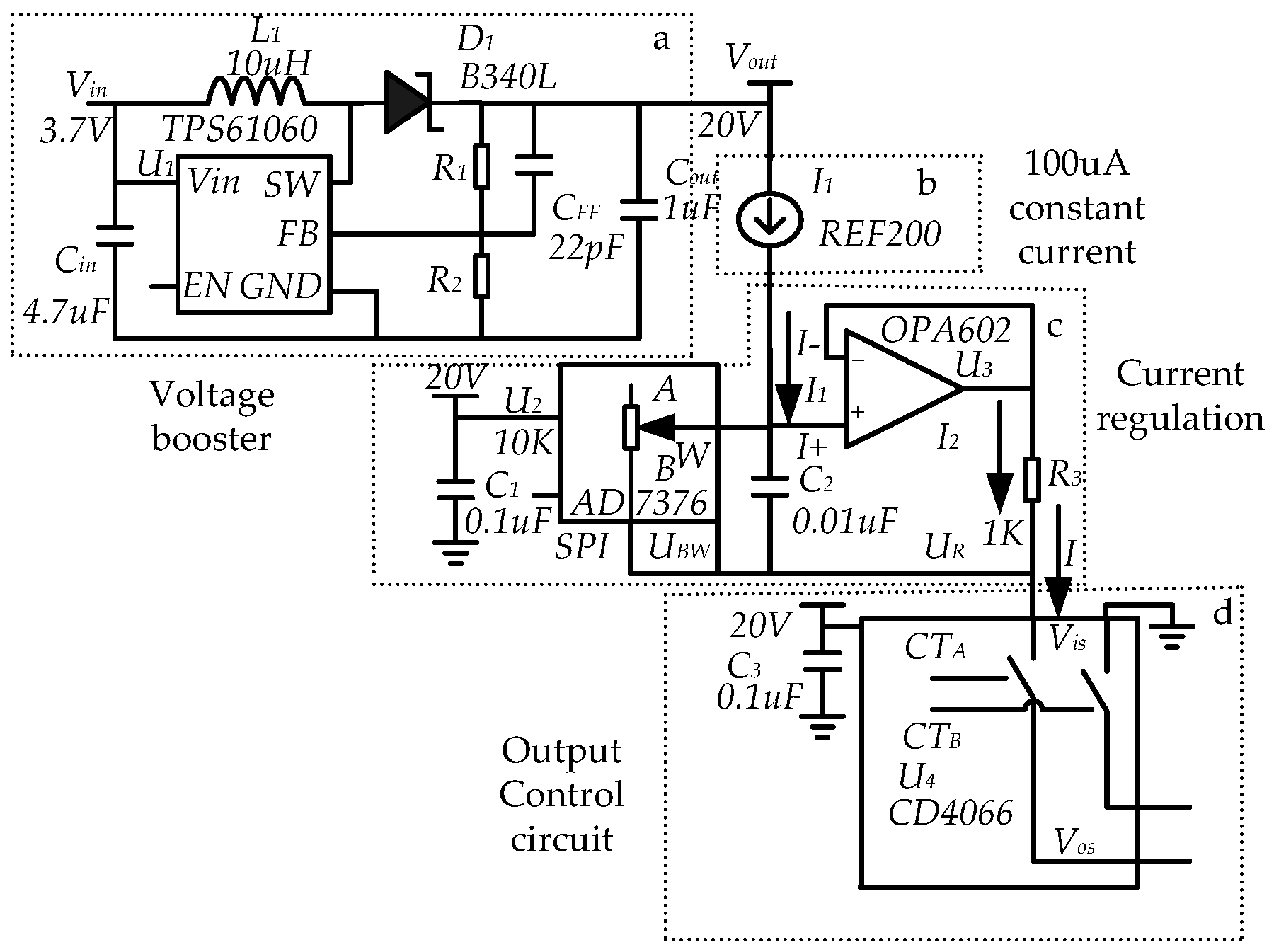
The schematic circuit diagram of reverse iontophoresis is shown in Figure 3. The circle can provide a variable current in the range of 100 μA~1.1 mA. The circuit is composed of four parts: voltage booster; 100 μA constant current; current regulation and output control circuit.
The current regulation of circuit is the core part of the circuit of reverse iontophoresis. It uses 100 μA constant current source through the operational amplifier and digitally controlled potentiometer to use the “virtual short” and “virtual-off” characteristics of the operational amplifier to achieve adjustable current output. The voltage U+ and U at the input operational amplifier (U3) are equal. The current passing operational amplifier (U3) is equal to 0 A.
U + = U
I + = I = 0 A
From Equations (2) and (3), the voltage UR across R3, and the voltage UBR across RBW are equal.
U B W = U R = I 1 × R B W = I 2 × R
Therefore,
I 2 = N × I 1
where I1 and I2 are the current through RBW and R3, respectively.
Combining Equations (1) and (2), the total current I at the output can be expressed by Equation (6).
I = ( I 1 + I 2 ) = ( N + 1 ) × I 1
In Equation (4), RBW is the access resistance of the AD7376 (Figure 3c), which is a high voltage digitally controlled potentiometer and whose range is 0~10 kΩ, so the total output current is 100 µA~1.1 mA.

2.4. Experiments on Skin Penetration In Vivo

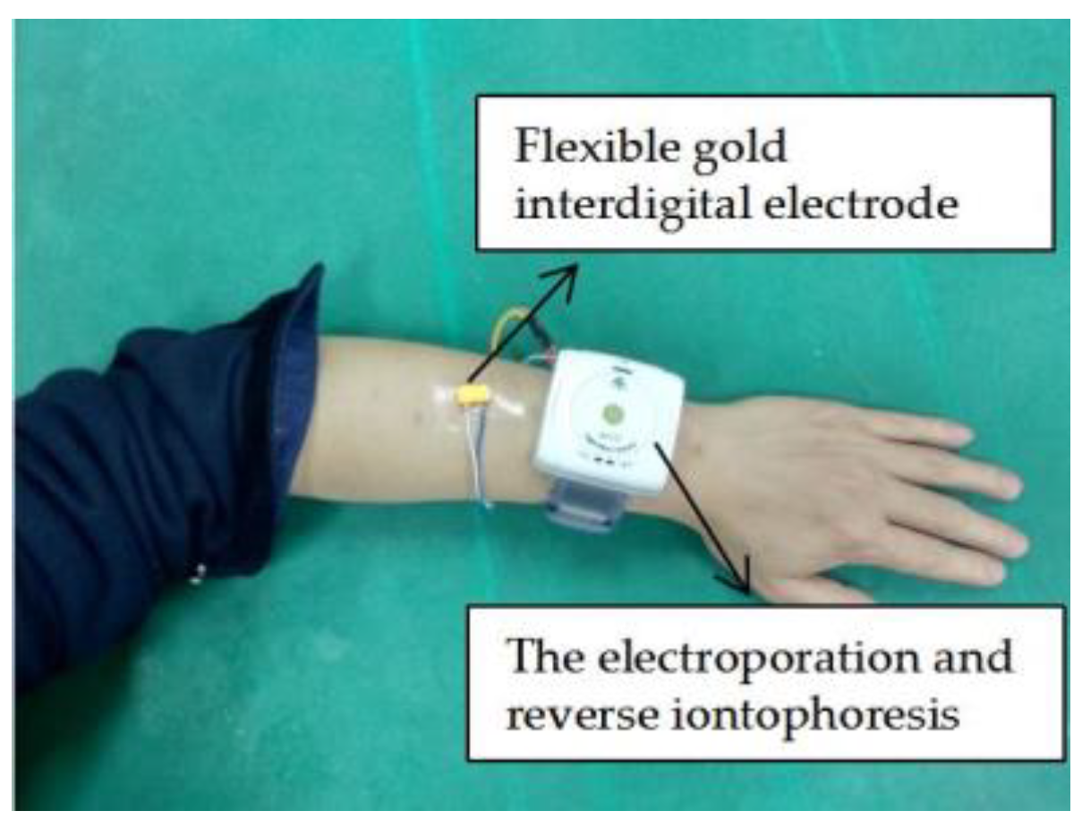
All experiments were conducted on skin of volunteers in vivo as shown in Figure 4. Different modes of electroporation and reverse iontophoresis were applied to the flexible gold interdigital electrode. Firstly, the effect of electroporation and reverse iontophoresis by measuring skin impedance was studied, then the optimal penetration-promoting experimental conditions were obtained. One-way analysis of variance was also used to determine whether there were significant differences between reverse iontophoresis parameters and the electroporation parameter for the test parameters of Zbefore/Zafter (f = 100 Hz) with Potentiosta EIS of gamry Reference600 electrochemical workstation [21]. The test conditions were controlled at 25 °C room temperature, 40% relative humidity through the air conditioner. When the electrode attached the skin after 40 min of stable period, the skin will produce sweat to humidity saturation. Test parameter of Zbefore/Zafter makes sense to avoid differences among various skins and test conditions. For the test parameter of Zbefore/Zafter, if its value is greater than 1, it means that the post-experimental skin impedance is smaller than the pre-experimental skin impedance.

3. Results and Discussion

3.1. Evaluation of the Circuit of Electroporation and Reverse Iontophoresis

The accuracy of the minimal configured electroporation and reverse iontophoresis circuit was evaluated by simulation test. The electroporation’s evaluation results are summarized in Figure 5 and Table 1 and Table 2. The load resistor of 100 k (VSMP2512100K, ±0.01%, EUREK, ShenZhen, China) is connected to the output by measuring waveform through a digital oscilloscope (MSO-X3054A, Agilent Technologies Inc., Santa Clara, CA, USA). Figure 5 shows the circle of electroporation being able to generate a pulsed electric waveform at various voltages with a specific pulse width. The circle is shown to be fully programmable configuration. Table 1 shows that the maximum voltage percentage error of electric pulses waveform is less than 3%. The percentage error of the circle on generating electric pulses with specific pulse width is found to be smaller than 1% and this means that the circle is accurate on generating electric pulse (Table 2).
The constant current for different waveform in revers iontophoresis was evaluated. Two resistors with resistance of 10 k (VSMP080510K, ±0.01%, EUREK, Shenzhen, China) and 100 k (VSMP2512100K, ±0.01%, EUREK, Shenzhen, China) as circuit load were used to simulate the resistance of skin [22]. These resistors are connected to the output of reverse iontophoresis. A digital oscilloscope (MSO-X3054A, Agilent Technologies Inc., Santa Clara, CA, USA) was used to measure the potential difference across the resistors. The magnitude of the current flowing through the resistor can be calculated from Ohm’s Law. The evaluation results of the reverse iontophoresis are summarized in Figure 6 and Table 3. Figure 6 shows the circle of reverse iontophoresis being able to generate a various pulsed electric waveform. It was found that the accuracy of the reverse iontophoresis’s constant current was about ±2% and accuracy of the circle of reverse iontophoresis’s pulse and bipolar current error timing, were smaller than ±1.5% (see Table 3). The error on timing when generating pulsed and bipolar waveform of currents may partly come from the microprocessor because it has an accuracy limit of ±1% on timing.

3.2. Evaluation of Electroporation and Reverse Iontophoresis for Promoting Penetration of Skin by Measuring Skin Impedance In Vivo

The device is Li-battery-powered (3.7 V). If the average working current of the system is 50 mA, it can work 70 cycles (one cycle of 17 min) under the battery capacity of 1000 mA/h and extract more tissue fluid with electroporation and reverse iontophoresis synergistically.
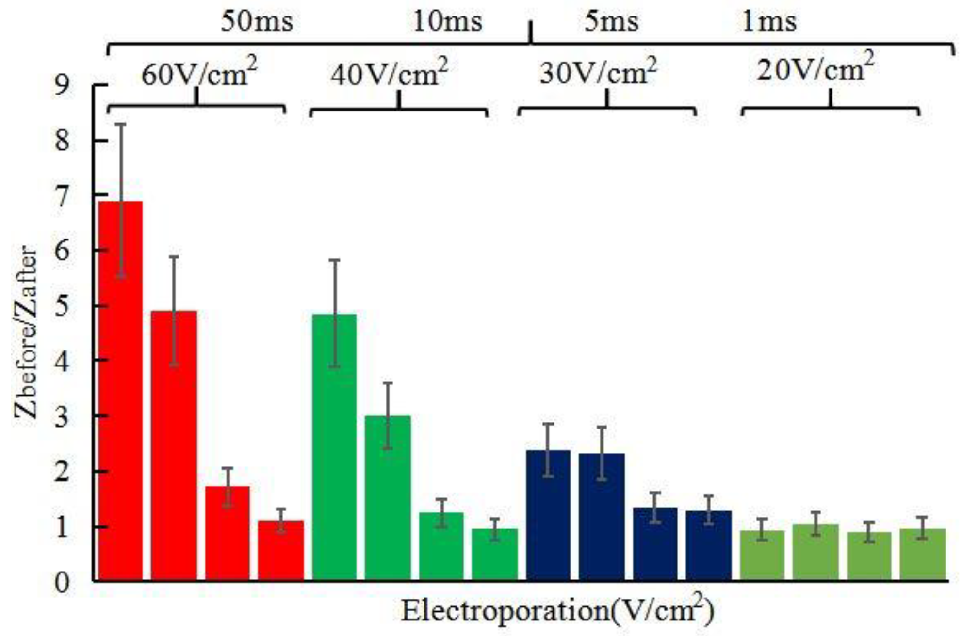
Our in vivo studies of promoting penetration of skin by electroporation, reverse iontophoresis and synergistical use of them are summarized in Figure 7, Figure 8, Figure 9 and Figure 10. Figure 7 shows the test results of the ratio of pre-experimental to post-experimental skin impedance under the condition of different pulse voltage (60~20 V/cm2), width (50~1 ms) of pulsed-monophasic electric waveform of electroporation. It was found that the increase of pulse voltage and width strength of electroporation could generally further decrease post experimental skin impedance under the same electroporation setting and this may be due to formation of nanochannels of ISF. The resulting drop in skin impedance is effectively proportional to the electrical field strength (pulse voltage × total pulse width), and this may be due to more or larger nanochannels being formed [16]. Figure 8 shows the effect of pulsed-monophasic and pulsed-biphasic electric waveform of electroporation on the ratio of pre-experimental to post-experimental skin impedance. It was observed that pulsed-biphasic electric waveform causes larger impedance changes than pulsed-monophasic electric waveform under the same conditions, which means that pulsed-biphasic electric waveform of electroporation has better promotion permeation efficiency than pulsed-monophasic waveform.
Figure 9 shows effect of reverse iontophoresis on the ratio of pre-experimental to post-experimental skin impedance. Under the same reverse iontophoresis setting, it was found that the increase of electrical field strength of reverse iontophoresis could generally further decrease post experimental skin impedance. Further, effect of reverse iontophoresis on the ratio of pre-experimental to post-experimental skin impedance decrease smaller than electroporation’s.
Figure 9. Effect of reverse iontophoresis (symmetricalbiphasic dc; different current density; reversed every 3 min during the 12 min) on the ratio of pre-experimental to post-experimental skin impedance (Zbefore/Zafter).
From the above studies, electroporation can reduce skin impedance more than reverse iontophoresis that means electroporation can improve skin penetration more. Figure 10 shows the pictures of the skin surface before and after experiment. If electric field strength of electroporation continues to increase, it is not clinically feasible for safety reasons and induction of pain sensation and involuntary muscle contractions. The electric field strength (>40 V/cm2) and pulse width (>10 ms) of electroporation are uncomfortable to some users (Figure 10a,b). However, in practical applications, such as using reverse iontophoresis to extract glucose of tissue fluids, long-time and high-intensity currents can easily cause skin irritation (Figure 10c,d). When the current intensity is greater than 300 μA/cm2, the skin is prone to damage. So that the optimized condition of electroporation on the human body is electric field strength (<40 V/cm2) and pulse width (<10 ms) and the condition of reverse iontophoresis on the human body is less than 300 μA/cm2.
Figure 11 shows the ratio of pre-experimental skin impedance to post-experimental skin impedance at various times after synergistically application of electroporation (electric field strength = 40 V/cm2, pulse width = 10 ms, number of pulses per second = 10, duration 5 min) and reverse iontophoresis (symmetrical biphasic dc; current density = 0.1 mA/cm2; reversed every 3 min during the 12 min). The combination of electroporation and reverse iontophoresis has additional benefits to promoting penetration. After one cycle of supplying the electroporation and revers iontophoresis, the impedance changes greatly before and after the experiment, which means that the skin has a strong penetration. The synergy of reverse iontophoresis and electroporation was more than doubled compared to the use of reverse iontophoresis alone. A steady decrease in the ratio with time was observed from more cycle penetration. Continuing to promote penetration, the value of Zbefore/Zafter changes gradually become smaller and slowly. In the process of promoting penetration, the skin was not significantly damaged. Therefore, Skin penetration promotion with electroporation and reverse iontophoresis synergistically can hopefully be improved at a lower current density and relatively weak electric field strength without damaging the skin.

3.3. In Vivo Evaluation of Electroporation and Reverse Iontophoresis Synergistically for ISF Extraction by Weight

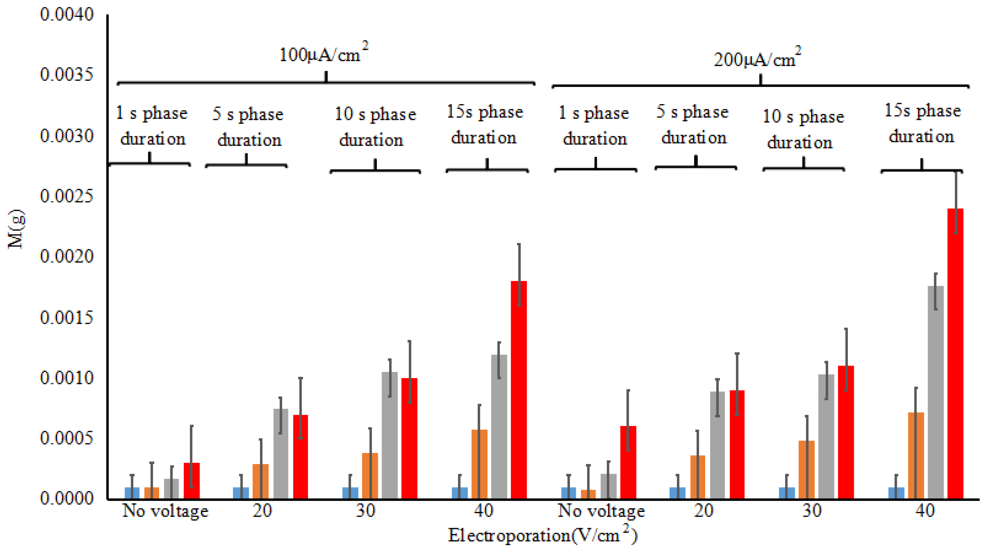
Under the safe conditions, the experiment of using electroporation and reverse iontophoresis synergistically to extract tissue fluid in vivo was carried out by standard ECG electrode. The extracted glucose is collected by a gel on the surface of the electrode. To accurately measure the amount of the extracted tissue fluid, the standard ECG electrodes are weighed separately before and after the electroporation and reverse iontophoresis experiment using precision electronic balance (ESJ182-4, precision 0.1 mg Shenyang Longteng Electronics Co., Ltd., Shenyang, China). Figure 12 shows the relationship of the weight of ISF extracted pre-experimental to post-experimental under different test conditions after synergistically application of electroporation (electric field strength = 40 V/cm2, pulse width = 10 ms, number of pulses per second = 10, duration 5 min) and reverse iontophoresis (symmetrical biphasic dc; current density = 0.1 mA/cm2; reversed every 3 min during the 12 min). At present, the glucose electrode can accurately measure the glucose concentration under the condition of 0.5 mg sample size. The amount of tissue fluid extracted by electroporation and reverse iontophoresis synergistically can reach up to 2.5 mg to meet blood glucose detection without harming human skin.

4. Conclusions

In this paper, a flexible interdigital microelectrode was designed for evaluating skin penetration by sensing impedance and a new method for noninvasive penetration promoting of skin with synergistical combination of electroporation and reverse iontophoresis has been demonstrated in vivo. First, a low-cost flexible gold interdigital microelectrode is designed to evaluate skin penetration promotion. Then, the battery-powered and programmable circuit of electroporation for high-electric pulse and reverse iontophoresis for a variable current is designed, which is suitable for wearable application in future. The electroporation can deliver precisely pulsed and pulsed-biphasic voltage with specific pulse width and number of pulses per second. Also, the reverse iontophore are precise when delivering a variable current in the range of 100 μA~1.1 mA with a various pulsed electric waveform. Using electroporation and reverse iontophoresis in vivo experiments, it is found that both electroporation and reverse iontophoresis can promote penetration of skin, but electroporation improves skin penetration more. If electric field strength of electroporation increase, the penetration of the skin increases correspondingly, but electric field strength of electroporation continues to increase that it is not clinically feasible for safety reasons. The reverse iontophoresis promotes the penetration of the skin relatively weakly, and the extraction of glucose and other tissue fluid target can be only extracted by reverse iontophoresis. The long-term, high-intensity current of reverse iontophoresis easily causes skin damage. Therefore, this method is expected to increase the penetration of the skin by interdigital microelectrode without harming the skin and is of great significance for the clinical application of noninvasive extracted tissue fluid for blood glucose measurement. The initial experiment was conducted only on a small group of people and the amount of tissue fluid extracted by electroporation and reverse iontophoresis synergistically can reach up to 2.5 mg to meet blood glucose detection. The selection of experimental conditions may only be suitable for this group of people. Future efforts will be concentrated on applying this method to large-scale populations in clinical applications and designed as a clinical wearable device to improve the amount of ISF for noninvasive blood glucose concentration detection.

Author Contributions

R.Z., C.W., F.L., L.D., Z.F., J.-T.L., C.-J.C. and Z.Z. collaborated on the research for various aspects of the paper. J.-T.L., C.-J.C. and Z.Z. conceived and designed the experiments; R.Z., C.W. performed the experiments; C.W. and F.L. analyzed the data; Z.F. and X.G. contributed reagents/materials/analysis tools; R.Z. wrote the paper; L.D. polished the paper.

Funding

This work was financially supported by Beijing Natural Science Foundation (Z160002) and the National Natural Science Foundation of China (61431019).

Conflicts of Interest

The authors declare no conflict of interest.

References

  1. Kovatchev, B.P. Diabetes Technology: Markers, Monitoring, Assessment, and Control of Blood Glucose Fluctuations in Diabetes. Scientifica 2012, 2012, 283821. [Google Scholar] [CrossRef] [PubMed]
  2. Hortensius, J.; Bijl, J.J.V.D.; Kleefstra, N.; Houweling, S.T.; Bilo, H.J.G. Self-Monitoring of Blood Glucose. Diabetes Educ. 2011, 38, 101–107. [Google Scholar] [CrossRef] [PubMed]
  3. International Organization for Standardization. In Vitro Diagnostic Test Systems—Requirements for Blood-Glucose Monitoring Systems for Self-Testing in Managing Diabetes Mellitus. Available online: https://www.iso.org/standard/54976.html (accessed on 4 May 2018).
  4. Garg, S.K.; Potts, R.O.; Ackerman, N.R.; Fermi, S.J.; Tamada, J.A.; Chase, H.P. Correlation of fingerstick blood glucose measurements with GlucoWatch biographer glucose results in young subjects with type 1 diabetes. Diabetes Care 1999, 22, 1708–1714. [Google Scholar] [CrossRef] [PubMed]
  5. Pitzer, K.R.; Desai, S.; Dunn, T.; Edelman, S.; Jayalakshmi, Y.; Kennedy, J.; Tamada, J.A.; Potts, R.O. Detection of hypoglycemia with the GlucoWatch biographer. Diabetes Care 2001, 24, 881–885. [Google Scholar] [CrossRef] [PubMed]
  6. Ce, F.D.A.; Wolf, B. Current development in non-invasive glucose monitoring. Med. Eng. Phys. 2008, 30, 541–549. [Google Scholar] [CrossRef]
  7. Wang, G.; Mintchev, M.P. Development of Wearable Semi-invasive Blood Sampling Devices for Continuous Glucose Monitoring: A Survey. Engineering 2013, 5, 42–46. [Google Scholar] [CrossRef]
  8. Kovatchev, B.P.; Shields, D.; Breton, M. Graphical and Numerical Evaluation of Continuous Glucose Sensing Time Lag. Diabetes Technol. Ther. 2009, 11, 139–143. [Google Scholar] [CrossRef] [PubMed]
  9. Giri, T.K.; Chakrabarty, S.; Ghosh, B. Transdermal reverse iontophoresis: A novel technique for therapeutic drug monitoring. J. Control. Release 2016, 246, 30–38. [Google Scholar] [CrossRef] [PubMed]
  10. Weaver, J.; Powell, K.; Tlanger, R. Control of Transport of Molecules across Tissue Using Electroporation. U.S. Patent 5,019,034, 18 May 1991. [Google Scholar]
  11. White, E.A.; Horne, A.; Runciman, J.; Orazem, M.E.; Navidi, W.C.; Roper, C.S.; Bunge, A.L. On the correlation between single-frequency impedance measurements and human skin permeability to water. Toxicol. Vitro 2011, 25, 2095–2104. [Google Scholar] [CrossRef] [PubMed]
  12. Schwingenschuh, S.; Scharfetter, H.; Martinsen, Ø.G.; Boulgaropoulos, B.; Augustin, T.; Tiffner, K.I.; Dragatin, C.; Raml, R.; Hoefferer, C.; Prandl, E.C.; et al. Assessment of skin penetration to topically applied drugs by skin impedance and admittance. Physiol. Meas. 2017, 38, N138–N150. [Google Scholar] [CrossRef] [PubMed]
  13. Li, D.; Wang, R.; Yu, H.; Li, G.; Sun, Y.; Liang, W.; Xu, K. A Method for Measuring the Volume of Transdermally Extracted Interstitial Fluid by a Three-Electrode Skin Resistance Sensor. Sensors 2014, 14, 7084–7095. [Google Scholar] [CrossRef] [PubMed]
  14. Choi, A.; Kim, J.Y.; Jo, S.; Jee, J.H.; Heymsfield, S.B.; Bhagat, Y.A.; Kim, I.; Cho, J. Smartphone-Based Bioelectrical Impedance Analysis Devices for Daily Obesity Management. Sensors 2015, 15, 22151–22166. [Google Scholar] [CrossRef] [PubMed]
  15. Li, D.; Pu, Z.; Liang, W.; Liu, T.; Wang, R.; Yu, H.; Xu, K. Non-invasive measurement of normal skin impedance for determining the volume of the transdermally extracted interstitial fluid. Measurement 2015, 62, 215–221. [Google Scholar] [CrossRef]
  16. Ivanic, R.; Novotny, I.; Rehacek, V.; Tvarozek, V.; Weis, M. Thin film non-symmetric microelectrode array for impedance monitoring of human skin. Thin Solid Films 2003, 433, 332–336. [Google Scholar] [CrossRef]
  17. Mamishev, A.V.; Sundararajan, K.; Yang, F.; Du, Y.; Zahn, M. Interdigital sensors and transducers. Proc. IEEE 2016, 92, 808–845. [Google Scholar] [CrossRef]
  18. Yamamoto, T.; Yamamoto, Y. Electrical properties of the epidermal stratum corneum. Med. Biol. Eng. 1976, 14, 151–158. [Google Scholar] [CrossRef] [PubMed]
  19. Zhao, Z.; Lu, F.; Wang, C.; Zhao, R.; Du, L.; Fang, Z. Evaluation of Skin Permeability Based on Impedance Detection by Microsensor Technology. J. Electron. Inf. Technol. 2018, 40. [Google Scholar] [CrossRef]
  20. Chizmadzhev, Y.A.; Indenborn, A.V.; Kuzmin, P.I.; Galichenko, S.V.; Weaver, J.C.; Potts, R.O. Electrical properties of skin at moderate voltages: Contribution of appendageal macropores. Biophys. J. 1998, 74, 843–856. [Google Scholar] [CrossRef]
  21. Ching, T.S.; Fu, L.S.; Sun, T.P.; Hsu, T.H.; Chang, K.M. Use of electroporation and reverse iontophoresis for extraction of transdermal multibiomarkers. Int. J. Nanomed. 2012, 7, 885–894. [Google Scholar] [CrossRef] [PubMed]
  22. Ching, C.T.S.; Buisson, Y.; Connolly, P. The effect of pulsed bipolar dc on the simultaneous extraction of glucose and lactate by reverse iontophoresis. Sens. Actuators B Chem. 2008, 129, 504–509. [Google Scholar] [CrossRef]
Figure 1. (a) Schematic of the flexible gold interdigital microelectrode multilayers; (b) The structure diagram of interdigital microelectrodes; (c) The fabricated multilayer microelectrode.
Sensors 18 01431 g001
Figure 2. Circuit diagram of the electroporation for high-voltage electric pulse.
Sensors 18 01431 g002
Figure 3. Circuit diagram of the reverse iontophoresis. (a) Voltage booster; (b) Constant current source; (c) Current regulation; (d) Output control circuit.
Sensors 18 01431 g003
Figure 4. Pictures of skin penetration promotion test with the device of electroporation and reverse iontophoresis.
Sensors 18 01431 g004
Figure 5. Output waveform of the micro electroporation’s circle.
Sensors 18 01431 g005
Figure 6. Output waveform of the reverse iontophoresis’s circle.
Sensors 18 01431 g006
Figure 7. Effect of different pulse voltage and width pulsed-monophasic electric waveform of electroporation on the ratio of pre-experimental to post-experimental skin impedance (Zbefore/Zafter). All skin impedance measurements were conducted at 100 Hz. For the electroporation setting, they all have the number of pulses per second of 10.
Sensors 18 01431 g007
Figure 8. Effect of pulsed-monophasic and pulsed-biphasic electric waveform of electroporation on the ratio of pre-experimental to post-experimental skin impedance (Zbefore/Zafter). All skin impedance measurements were conducted at 100 Hz. For the electroporation setting, they all have the number of pulses per second of 10 and the electric field strength of 40 V/cm2.
Sensors 18 01431 g008
Figure 9. Effect of reverse iontophoresis (symmetricalbiphasic dc; different current density; reversed every 3 min during the 12 min) on the ratio of pre-experimental to post-experimental skin impedance (Zbefore/Zafter).
Sensors 18 01431 g009
Figure 10. Pictures of the skin surface before and after each experiment. (a,b) Before and after experiment, respectively, with application of electroporation (pulse voltage density = 60 V/cm2, pulse width = 10 ms; number of pulses per second = 10); (c,d) Before and after experiment, with application of reverse iontophoresis (Symmetrical biphasic dc, current density = 0.3 mA/cm2; reversed every 3 min during the 12 min).
Sensors 18 01431 g010
Figure 11. Effect of electroporation (electric field strength = 40 V/cm2; pulse width = 10 ms; number of pulses per second = 10, duration 5 min) and reverse iontophoresis (symmetrical biphasic dc; current density = 0.1 mA/cm2; reversed every 3 min during the 12 min) on the ratio of pre-experimental to post-experimental skin impedance at various times after the promotion penetration experiment.
Sensors 18 01431 g011
Figure 12. Effect of electroporation (electric field strength = 0~40 V/cm2, pulse width = 10 ms, number of pulses per second = 10, duration 5 min) and reverse iontophoresis (symmetrical biphasic dc; current density = 0.1~0.2 mA/cm2; reversed every 3 min during the 12 min) on the difference of ISF extraction pre-experimental to post-experimental by measuring weight under different conditions.
Sensors 18 01431 g012
Table 1. Error estimation of the electroporation on generating electric pulses with specific pulse voltage.
ParametersLoad = 100 k,
Pulse Width = 1 ms
Load = 100 k,
Pulse Width = 5 ms
Load = 100 k,
Pulse Width = 10 ms
Load = 100 k,
Pulse Width = 50 ms
Pulses per Second = 10 PPSPulses per Second = 10 PPSPulses per Second = 10 PPSPulses per Second = 10 PPS
VoltageSetting (V)20304060203040602030406020304060
Measured voltage (V)Mean19.7629.6839.5359.2719.8629.6239.5659.4719.7929.6839.7359.5719.8629.8839.7359.37
SD0.260.410.640.870.310.380.610.820.200.350.550.670.200.410.440.67
Error (%)2.502.432.782.672.252.542.622.252.052.232.051.831.701.771.782.17
Table 2. Error estimation of the electroporation on generating electric pulses with specific pulse width.
ParametersLoad = 100 k, Pulse Voltage = 1 ms
Pulses per Second = 10 PPS
Pulse width Setting (ms)1.005.0010.0050.00
Measured pulse width (ms)Mean1.0025.00410.01550.045
SD0.0070.0490.0650.089
Error (%)0.9000.9800.6500.178
Table 3. The results (mean ± SD) of simulated accuracy of the variable current source at two different load resistors.
Program Setting Stored Inside the Microprocessor Current Strength (μA)Resistance of Resistor (k)Measured Parameters
The Current Strength of the Accuracy (μA)The Pulse and Bipolar Current Error Timing (t > 1 μS)
100 (dc)10100 ± 0.65%-
300 (dc)10300 ± 0.73%-
1100 (dc)101100 ± 1.5%-
300 (pulse)10300 ± 0.83%<1.1%
300 (bipolar)10300 ± 0.83%<1.3%
100 (dc)100100 ± 0.85%-
300 (dc)100200 ± 1.24%-
1.1 (dc)100200 ± 1.24%-
100 (pulse)100100 ± 0.85%<1.2%
100 (bipolar)100100 ± 0.85%<1.5%