Article

A High-Precision Method for Dynamically Measuring Train Wheel Diameter Using Three Laser Displacement Transducers

Key Lab of Luminescence and Optical Information, Ministry of Education, Beijing Jiaotong University, Beijing 100044, China
*
Author to whom correspondence should be addressed.
Sensors 2019, 19(19), 4148; https://doi.org/10.3390/s19194148
Submission received: 22 August 2019 / Revised: 16 September 2019 / Accepted: 23 September 2019 / Published: 25 September 2019
(This article belongs to the Section Optical Sensors)

Abstract

:
Wheel diameter is a significant geometric parameter related to the safe operation of trains, and needs to be measured dynamically. To the best of the authors’ knowledge, most existing dynamic measurement methods and systems do not meet the requirement that the wheel diameter measurement error for the high-speed vehicle is less than 0.3 mm. In this paper, a simple method for dynamically and precisely measuring train wheel diameter using three one-dimensional laser displacement transducers (1D-LDTs) is proposed for the first time, and a corresponding measurement system which was developed is described. The factors that affect the measurement accuracy were analyzed. As a main factor, rail deformation caused by the wheel-rail interaction force at low (20 km/h) and high (300 km/h) speeds was determined based on the combination of multi-body dynamics and finite element methods, and the effect of rail deformation on measurement accuracy is greatly reduced by a comparative measurement. Field experiments were performed to verify the performance of the developed measurement system, and the results of the repeatability error and measurement error of the system were both less than 0.3 mm, which meets the requirement of wheel diameter measurements for high-speed vehicles.

1. Introduction

Wheelsets are a key component of trains. The wear of wheel treads is becoming more serious, due to continuous increases in the speed and load of trains [1]. As wheel diameter is a significant geometric parameter related to the safe operation of trains, the diameter differences between the wheels of one wheelset, one bogie, one car, and one train must be controlled under a safe limitation. For example, the diameter difference within one wheelset of the high-speed vehicle in operation must be less than 0.3 mm, according to European Norm EN 15313 [2]. The wheel diameter changes every day because of wheel wear; thus, the dynamic measurement of diameter to detect overrun wheels in time is critically important.
Currently, there are many kinds of wheel diameter measurement methods and devices, which can be classified into two categories: shop measurements and field measurements. Shop measurements are usually performed periodically in the train garage. Traditionally, a measuring gauge [3] is utilized to manually measure the diameter based on the three-point measurement method. It is unreliable, as the skill of the user can significantly influence the result. To improve the measuring reliability, Torabi et al. proposed a method based on image processing with a measurement uncertainty of 0.4 mm [4]. Feng et al. proposed a method which uses parallelogram mechanisms together with one-dimensional laser displacement transducers (1D-LDTs) [5]. A non-contact measurement method using the LDT and CCD was put forward by Wu et al. [6] with a measuring accuracy of 0.2 mm. The underfloor wheelset lathe can be used in geometric parameter measurements of the wheel tread with the wheel remaining assembled to the bogie [7]; the accuracy of measuring the diameter is within 0.1 mm. The main disadvantage of shop measurement methods is that a potential safety hazard exists, because these methods cannot identify overrun wheelsets in time. Filed measurement is consequently the only choice for the timely discovery of overrun wheelsets. 1D-LDT and structural light vision transducers (SLVTs) are the two main methods for field diameter measurements. Chen et al. used commercial SLVTs to measure the geometric parameters of wheel tread, including wheel diameter [8,9]. Similar measurement systems were developed by corporations [10,11,12]. These methods used multiple sets of transducers which required global calibration on-site to unify the coordinated system; this approach is occasionally difficult, and the diameter measurement error is about 0.5 mm, which cannot meet the requirement of being less than 0.3 mm for the wheels of a high-speed vehicle, according to Chinese Standards [13]. The measurement accuracy of diameter can be improved by 1D-LDT, as the 1D-LDT has higher measurement accuracy. Naumann et al. proposed a measurement system using at least 26 1D-LDTs [14], which is difficult to apply on-site. We propose a series of methods using 1D-LDTs [15,16]. One 1D-LDT was used to dynamically measure the diameter and an eddy current sensor was used to locate the position of the wheel [15]. In order to improve the accuracy of the positioning, two eddy current sensors were used [16]. However, the measurement accuracy of these methods will be significantly reduced due to wear of the wheel tread and rail top. To solve this problem, we further proposed a simple method using three 1D-LDTs. The corresponding measurement system was developed, and field experiments were carried out. The results show that the repeatability error and measurement error are less than 0.3 mm, which meet the requirement of Chinese high-speed railway operations [13], and pave a new way for dynamically measuring wheel diameters with greater precision. The rest of this paper is organized as follows. The proposed method is described in Section 2. Section 3 analyses the factors that affect the measuring accuracy. In Section 4, the results of field experiments are presented. Finally, the conclusions of this study are given in Section 5.

2. Measurement Method

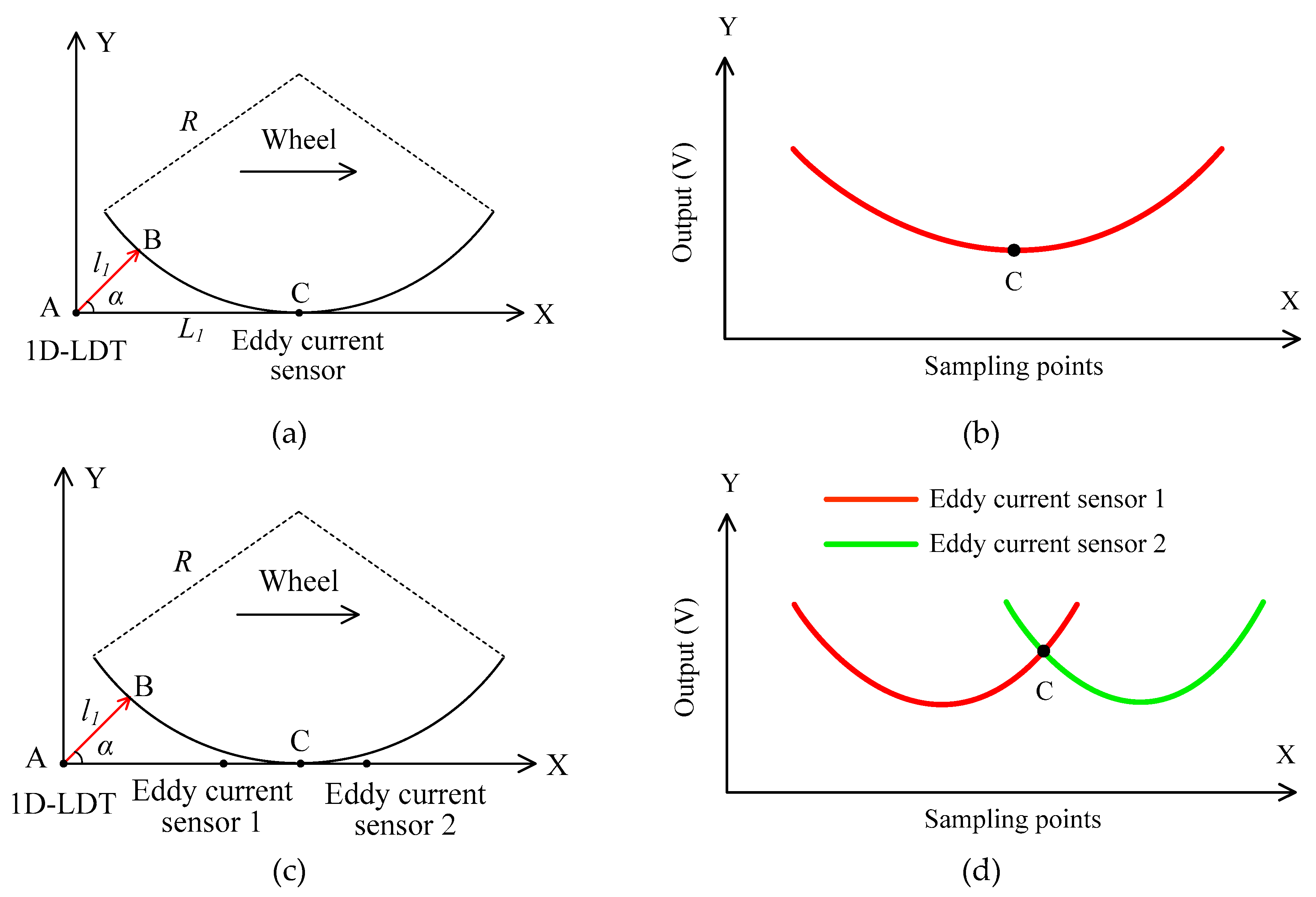
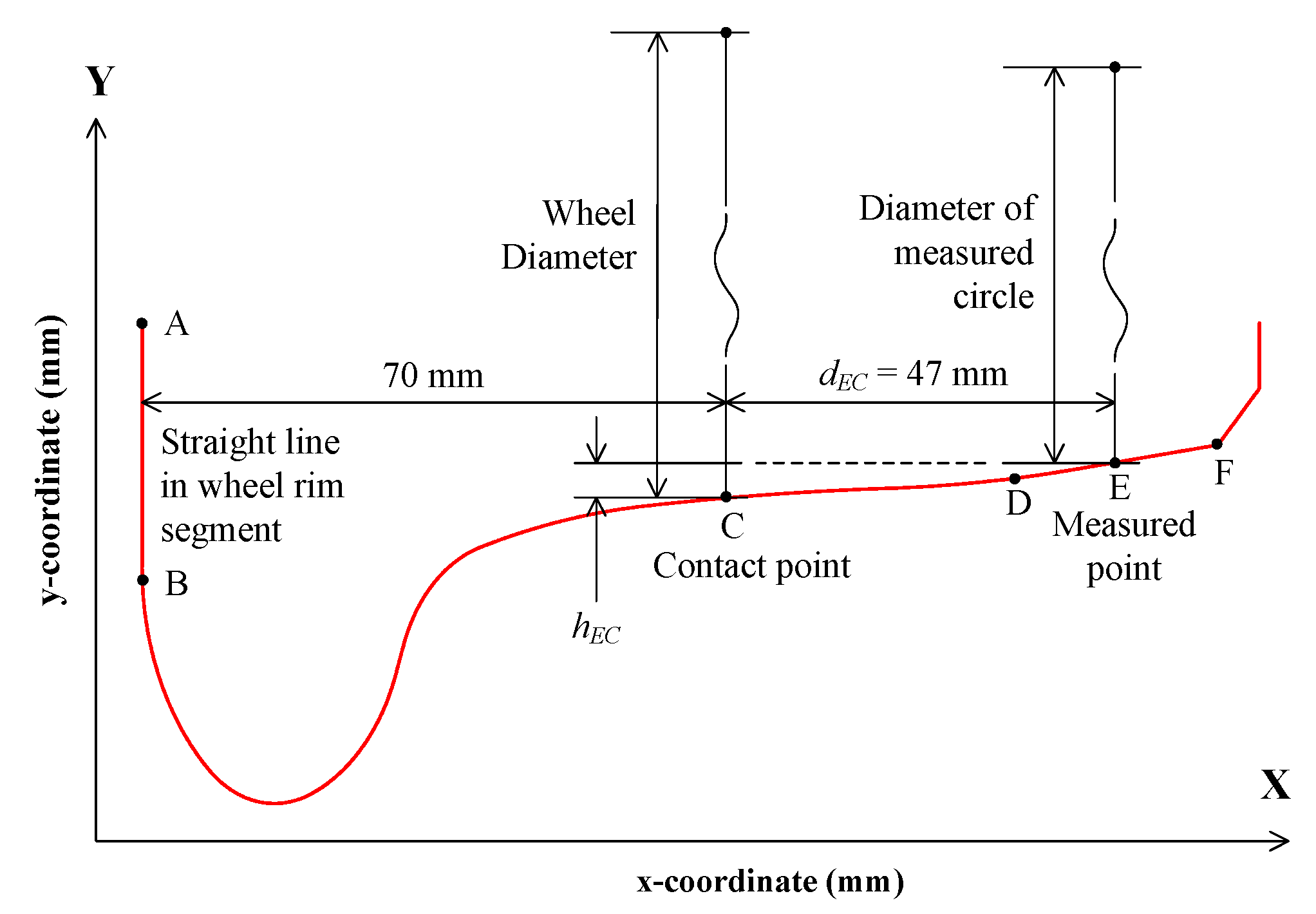
2.1. Measurement Method Based on One 1D-LDT

Figure 1a shows the method for dynamically measuring the wheel diameter using one 1D- LDT and eddy current sensor [15]. As shown in Figure 1a, the 1D-LDT is fixed on the rail at point A with an angle α. When the train wheel runs on the rail along the X axis, the 1D-LDT measures the distance l1 between the transducer and the wheel tread at the point of B. The coordinate of B is (l1cosα, l1sinα). An eddy current sensor is mounted at point C to measure the wheel position, which is L1 away from point A. In fact, the eddy current sensor can be replaced by 1D-LDT. Thus, the equation of the circle is expressed as
( x L 1 ) 2 + ( y R ) 2 = R 2 .
where, R is the radius of the wheel. According to the measured distance l1 of the 1D-LDT when the wheel is in the position of point C, the diameter is calculated by
D = L 1 2 + l 1 2 l 1 sin α 2 L 1 tan α .
The eddy current sensor is used to measure the wheel position; however, the output of the eddy current sensor changes slowly when it is closer to the lowest point of the wheel, as shown in Figure 1b. As a result, the positioning accuracy is low, which greatly influences the accuracy of diameter measurements. To improve the accuracy of the positioning, two eddy current sensors [16] are mounted symmetrically at appropriate positions on both sides of the point C, as shown in Figure 1c, and the two outputs of the eddy current sensors change quickly at the point C, as shown in Figure 1d. There is a zero position of the difference between the two outputs, and this point is used to determine the position of the wheel, thus improving the positioning accuracy and the diameter measurement accuracy.

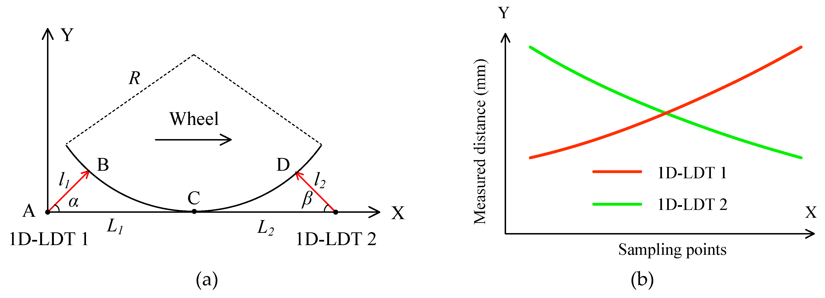
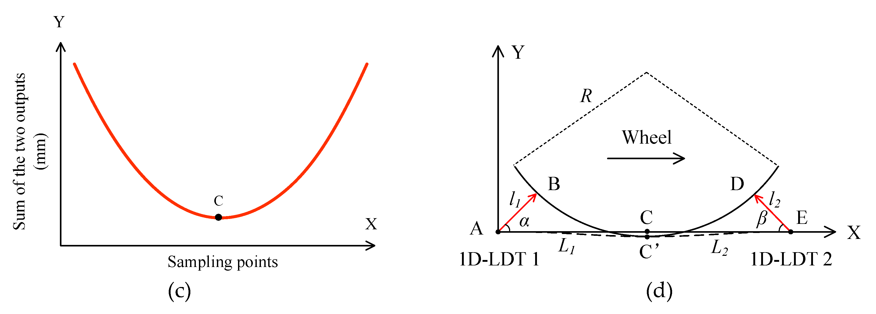
2.2. Measurement Method Based on Two 1D-LDTs

To reduce the influence of roundness on the diameter measurements, two 1D-LDTs were used, as shown in Figure 2a. The second transducer is fixed on the rail at the point E with an angle β, which is L2 away from the point C. When the train wheel runs on the rail along the X axis, two transducers can measure the distances l1 and l2 synchronously, and the outputs of the two 1D-LDTs are shown in Figure 2b. Figure 2c shows the sum of the two outputs of 1D-LDTs. From Figure 2c, there is a minimum value which is used to determine the wheel position with a high level of accuracy. Thus, the measured distances l1 and l2 of the two 1D-LDTs are determined when the wheel is in the position of point C.
According to the Equation (2), the diameter of wheel is expressed as
D = L 1 2 + l 1 2 2 l 1 sin α L 1 tan α + L 2 2 + l 2 2 2 l 2 sin β L 2 tan β .

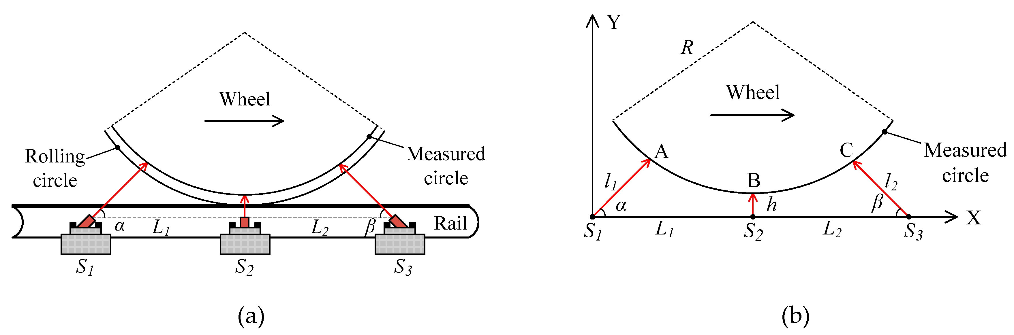
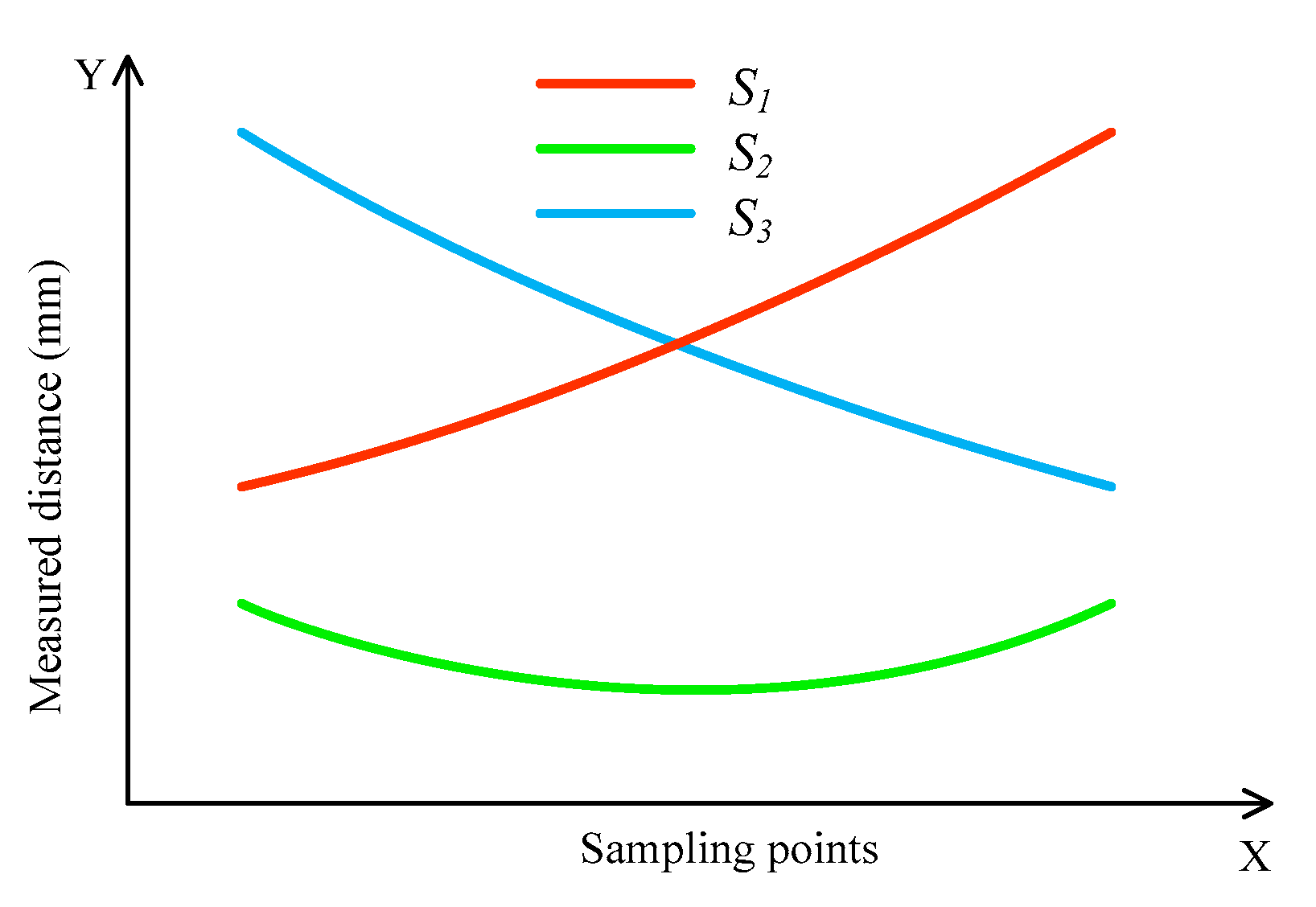
2.3. Measurement Method Based on Three 1D-LDTs

The above three methods (in Figure 1a,c, and Figure 2a) are based on the assumption that the point C between the wheel and the rail is fixed. In fact, it will change, due to wear of the wheel tread and rail top. If the point C is changed to C′, as shown in Figure 2d, it will yield a measurement error for the 1D-LDT, thereby significantly reducing the measurement accuracy. To solve this problem, a simple method using three 1D-LDTs is proposed.
Figure 3a shows the setup for dynamically measuring the diameter using three 1D-LDTs, which are called S1, S2, and S3, respectively. Three transducers are mounted on the standard rail. The distances between S2 to S1 and S3 are L1 and L2, respectively. In addition, the emitting spots of S1 and S3 are projected to the wheel tread at the angles of α and β, respectively.
Figure 3b shows the schematic diagram of diameter measurement. From Figure 3b, the coordinate of point A is (l1cosα, l1sinα), and the equation of the measured circle is expressed as
( x L 1 ) 2 + ( y R h ) 2 = R 2 .
where R is the radius of the measured circle. From Equation (4), the diameter of the measured circle D1 is calculated by
D 1 = L 1 2 + l 1 2 + h 2 2 L 1 l 1 cos α 2 l 1 h sin α l 1 sin α h .
Similarly, the diameter of the circle D2 measured by S2 and S3 can be obtained. To reduce the influence of roundness, the average of the two diameters D1 and D2 is the optimal diameter Dm of the measured circle. With L1 = L2 = L and α = β, it is expressed by
D m = L 2 + l 1 2 + h 2 2 L l 1 cos α 2 l 1 h sin α 2 l 1 sin α 2 h + L 2 + l 2 2 + h 2 2 L l 2 cos α 2 l 2 h sin α 2 l 2 sin α 2 h .
When the train wheel passes through the measurement system, the three transducers synchronously measure the distance between the transducer and the wheel tread. Figure 4 shows the typical outputs of the transducers. The closest distance h between S2, and the measured circle can be obtained by fitting using the sampling points of S2. Similar to the method using two 1D-LDTs, the sum of the outputs of S1 and S3 is used to determine the wheel position. Then, the measured distances l1 and l2 of the other two transducers S1 and S3 are obtained, respectively. Finally, the diameter of the measured circle can be determined according to Equation (6). Different from the methods shown in Figure 1a,c, and Figure 2a, S2 in Figure 3b is used to measure distance h, rather than for determining the wheel position. If there is the wear on the wheel tread and rail top, the distance h, l1, and l2 will be changed correspondingly, and Equation (6) is still stable; thus, the diameter measurement accuracy will not be affected by the wear of the wheel tread and rail top.
Figure 5 shows the wheel tread profile. Point C is defined as the contact point between the wheel and the rail, which is 70 mm to the straight line AB in the wheel rim segment. The rolling circle consists of all the contact points around the wheel, the diameter of which is defined as the wheel diameter. Point E is the measured point of the 1D-LDT, which is in the straight line DF. The distance dEC between the measured point and the contact point is known by the layout of the three 1D-LDTs, the typical value of which is 47 mm. It should be noted that Dm in Equation (6) is not the wheel diameter, but the diameter of the measured circle. To measure the wheel diameter, the distance hEC between the measured point and contact point should be determined. Thus, the SLVT is used to measure the wheel tread profile, the measurement principle of which is described in the reference [17].
The two-dimensional coordinates of the wheel tread profile can be obtained by the SLVT. After that, the straight line AB can be obtained by fitting; then, the coordinate of contact point C is determined by the distance to the line AB. As the distance dEC is known, the coordinate of the measured point can be accurately determined. The difference between the y-coordinates of the two points is hEC, and the wheel diameter D can be obtained by
D = D m + 2 h E C .

3. Measurement Error Analysis

From Equations (6) and (7), the diameter can be calculated simply by measuring the special distances of l1, l2, h, and hEC. hEC is measured by the SLVT, and the measurement error can be less than 0.1 mm [18], which results in an error for measuring the diameter of less than 0.2 mm. There are four other primary factors that can influence the diameter measurement accuracy: The S-shaped motion of the wheel, the measurement error of 1D-LDT, the positioning error of the wheel, and the rail deformation caused by the wheel-rail interaction force. The measurement errors caused by the S-shaped motion of the wheel and the rail deformation are systematic errors for which it is possible to compensate. The measurement errors caused by the measurement error of 1D-LDT and the positioning error of the wheel are random errors, for which it is not possible to compensate. In the following section, these factors are analyzed and simulated in theory, where L is set to 480 mm, h is set to 80 mm, α is set to 60°, and l is set to 285 mm.

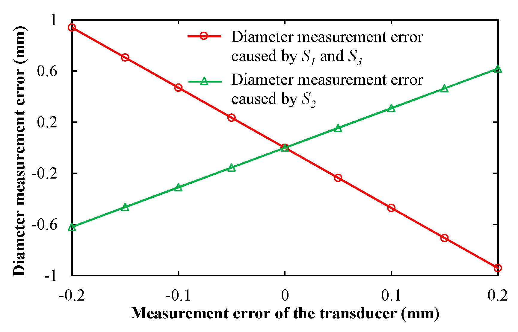
3.1. Measurement Error of the Transducer

Figure 6 shows the theoretical stimulation results of the diameter measurement error caused by the measurement errors of S1 and S3, as well as S2. In Figure 6, the measurement error of the transducer is set between −0.2 and 0.2 mm at intervals of 0.05 mm. In fact, the measurement error of the transducer can be less than 0.05 mm [19]; thus, the diameter measurement error is less than 0.24 mm caused by the measurement errors of S1 and S3. For S2, it is less than 0.15 mm.

3.2. Positioning Error of the Wheel

Figure 7 shows the theoretical stimulation result of the diameter measurement error produced by the wheel positioning error, where the positioning error is zero when S2 is below the lowest point of the wheel. According to Equation (6), if the positioning error is within 5.0 mm, the diameter measuring error is less than 0.13 mm. Actually, it is easy for the wheel positioning error being controlled to be less than 1 mm based on the sum of the outputs of S1 and S3; thus, the diameter measurement error caused by the wheel positioning error is negligible.

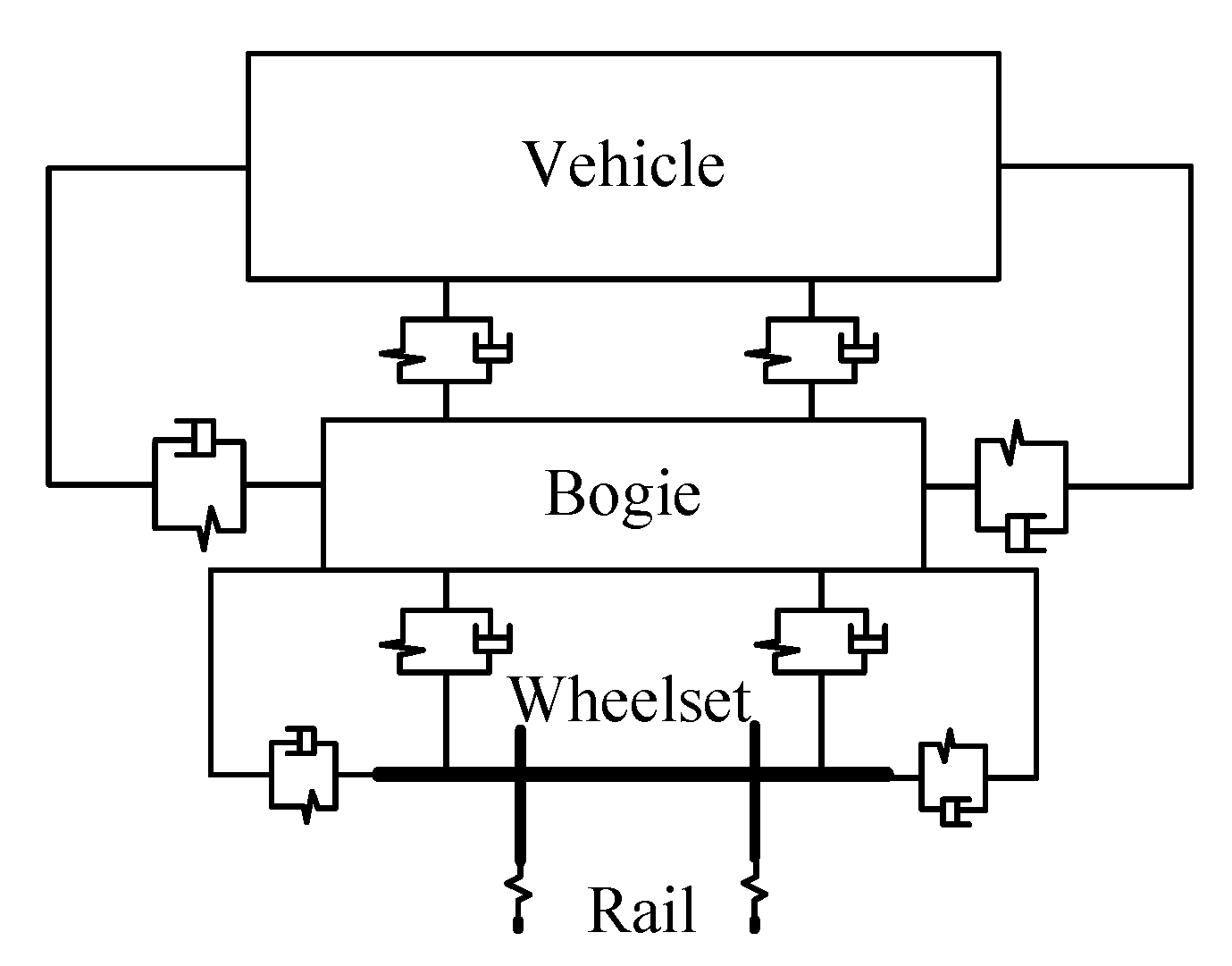
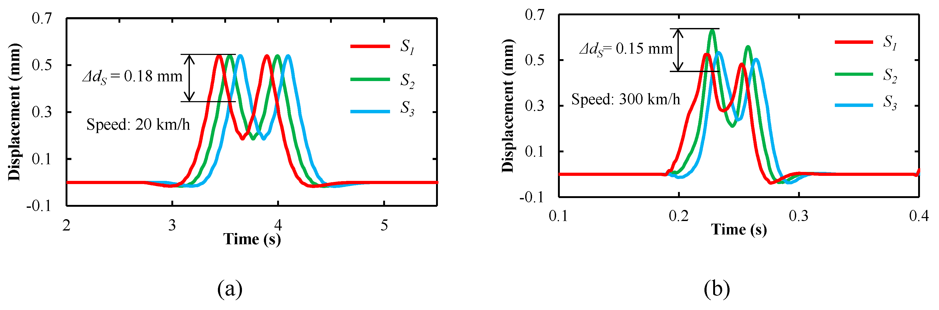
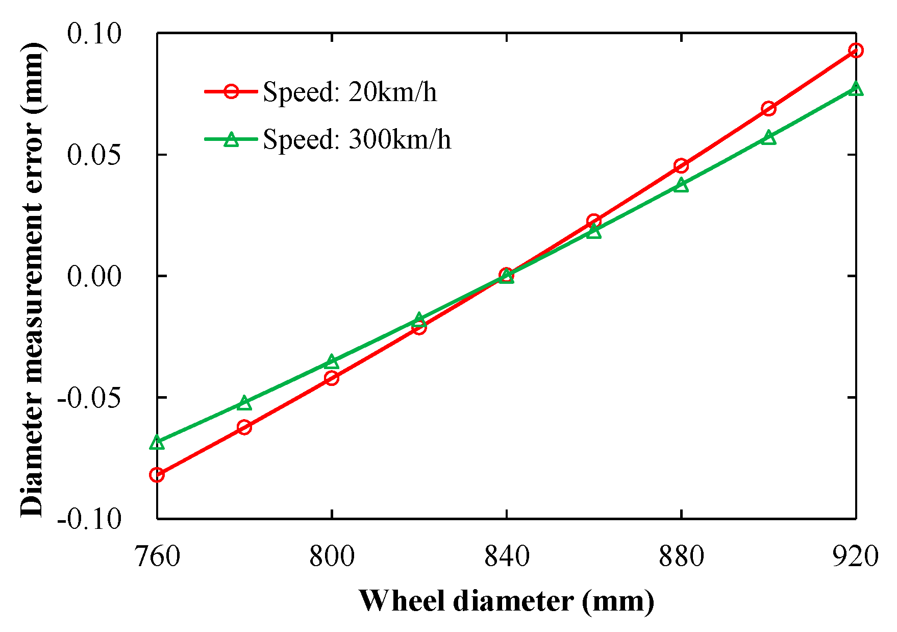
3.3. S-Shaped Motion of the Wheel

Figure 8 shows the tread profile with the S-shaped motion of the wheel, wherein the standard tread profile is obtained by measuring the standard wheel using the SLVT. Owing to the S-shaped motion of wheel, the contact point C has changed to C′, and the measured point E has changed to E′ in the Y-axis direction. In Figure 4, the S-shaped motion displacement ΔdEC can be measured by the difference between the two straight lines in the wheel rim segment. Thus, the corrected distance dEC between the contact point and the measurement point is expressed by
d EC = d EC Δ d EC .
Here, dEC is used to search the measured point in the tread profile with the S-shaped motion of the wheel, and the corrected distance hEC can be determined. In this way, the influence of the S-shaped motion of the wheel on the diameter measurement can be eliminated in theory.

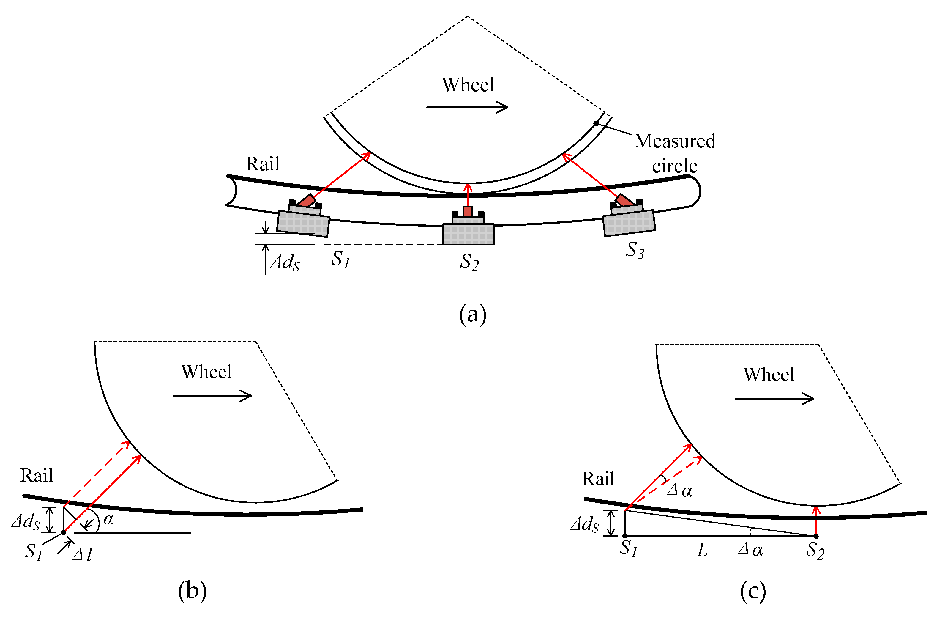
3.4. Rail Deformation

Rail deformation caused by the wheel-rail interaction force is inevitable. As shown in Figure 9a, there is a distance ΔdS in the vertical direction of S1 to S2 and S3 to S2 because of rail deformation when the train passes thorough the transducers; thus, the measured distance error Δl of the transducer and the direction error Δα of the laser beam are produced. From Figure 9b, Δl can be expressed by
Δ l = Δ d S sin α .
From Figure 9c, Δα is obtained by
Δ α = arctan ( Δ d S L ) .
To analyze the effect of rail deformation on diameter measurement, ΔdS is a key parameter and should be determined. A vehicle-track, rigid-flexible coupling model was established using the combination of multi-body dynamics and finite element methods, and rail deformation was analyzed at low and high train speeds.
Figure 10 shows a dyna-mic model of the vehicle system, wherein the vehicle and the track constitute the vehicle-track coupling dynamic system. The vehicle model is a multi-body system composed of one body, two frames, four wheels, and the primary and secondary suspension systems. The finite element analysis software Abaqus CAE [20], which is developed by Dassault Systems and it is a complete solution for finite element modeling, visualization, and process automation, was used to produce the flexible rail at first, and the elastic part was then generated using the software Simpack [21], which is a general multi-body simulation software enabling analysts and engineers to simulate the non-linear motion of any mechanical or mechatronic system. The values of the parameters used in the simulation are listed in Table 1. Using a combination of the structural parameters and suspension parameters of the vehicle system, the vehicle-track rigid-flexible coupling model was established.
Displacement-time curves of S1, S2, and S3 at the different speeds of the train using the vehicle-track rigid-flexible coupling model are shown in Figure 11. The displacement-time curve of the transducer can represent rail deformation, as it is fixed on the rail. From Figure 11a,b, rail deformation was different at low and high speeds. At a low speed of 20 km/h, the distance ΔdS was 0.18 mm. At a high speed to 300 km/h, it was 0.15 mm. From Equation (9), the measured distance errors Δl were 0.16 and 0.14 mm at speeds of 20 and 300 km/h, respectively. Thus, the diameter measurement errors are ±0.75 and ±0.66 mm according to Figure 6.
Figure 12 shows the diameter measurement error caused by the angle change of the laser emission. According to Equation (10), Δα were 0.019° and 0.017° at low and high speeds of the train, respectively. Thus, the diameter measurement errors are ±0.19 and ±0.17 mm.
The diameter measurement errors caused by the rail deformation are systematic and can be compensated by the comparative measurement with a standard wheel whose diameter is known. Thus, Equation (6) should be expressed as
D m = D m + ( l 1 l 1 ) ( L 2 sin α h 2 sin α 2 L h cos α + h l 1 + h l 1 l 1 l 1 sin α ) 2 ( l 1 sin α h ) ( l 1 sin α h ) +       ( l 2 l 2 ) ( L 2 sin α h 2 sin α 2 L h cos α + h l 2 + h l 2 l 2 l 2 sin α ) 2 ( l 2 sin α h ) ( l 2 sin α h )
where Dm′ is the standard diameter of the measured circle in the standard wheel, l1′ and l2′ are the output distances of S1 and S3 to measure the standard wheel, respectively. Figure 13 shows the simulation results based on the comparative measurement, where the diameter of the standard wheel is 840 mm. For both low and high speeds, the diameter measurement error is less than 0.1 mm, with the wheel diameter being in a range of 760–920 mm. Thus, the influence of rail deformation on diameter measurement can be greatly reduced.

4. Field Experiments

The corresponding system for dynamically measuring the train wheel diameter based on the aforementioned method was developed, and was installed in the storage line of Yinchuan railway station vehicle depot, China, as shown in Figure 14a. Figure 14b,c show images of the 1D-LDTs and SLVTs, respectively. Here, three developed 1D-LDTs and two developed SLVTs were used. In Figure 14b, the three 1D-LDTs were installed in a box, which was mounted on the standard rail. In the box, S1 and S3 were mounted symmetrically, 480 mm away from S2. The lasers of S1 and S3 were at an angle of 60°. In addition, S2 had a measurement range of 40 mm, and the start measurement distance was 90 mm. For S1 and S3, the measurement range was 80 mm, the start measurement distance was 280 mm. A grating ruler (LG-50, accuracy: 0.1 μm, resolution: 50 nm) was used to calibrate the 1D-LDTs. The results showed that the measurement accuracy was 20 μm for S2, and that was 15 μm for S1 and S3. In Figure 14c, the SLVT was mainly composited by a camera (acA1600-20gm, Basler, pixel: 1626 × 1236), a lens (M1620-MPW2, Computer, focal length: 16 mm), and a line laser (EL65L200IG9, Elite, power: 200 mW), which was installed in an individual box. Two SLVTs, mounted on both sides of the standard rail, were used to produce a complete tread profile. When the train wheel passed through the measurement system, the three 1D-LDTs sampled synchronously with a frequency of 5 kHz, and the two SLVTs were triggered by a photoelectric switch. The real outputs of the three 1D-LDTs and two SLVTs are shown in Figure 14d,e respectively.
To verify the performance of the developed measurement system, the diameters of four wheels with a small roundness error in a train car (ID: 350122), which passed through the measuring system three times in a month, were dynamically measured. The experimental information and results are shown in Table 2.
Table 2 shows that our system has a good performance in repeatability error. The repeatability error of wheels 2 and 4 is 0.09 mm, and the maximum repeatability error is 0.27 mm. In addition, the diameter of wheel 4 was measured by an underfloor wheelset lathe (U2000-150, hegenscheidt, diameter measurement accuracy: 0.1 mm); the result was 889.38 mm. Thus, the deviation between our system and the lathe is 0.22 mm. Consequently, the repeatability and measurement errors of the proposed system are less than 0.3 mm, which meets the requirement of Chinese high-speed railway operations.

5. Conclusions

In this paper, a high-precision method using three 1D-LDTs for dynamically measuring wheel diameters was first proposed. The factors that influenced measurement accuracy were analyzed. As a main factor, the rail deformation caused by the wheel-rail interaction force at low (20 km/h) and high (300 km/h) speeds was determined based on the combination of the multi-body dynamics and finite element methods, and the effect of rail deformation on measurement accuracy was greatly reduced by a comparative measurement. A corresponding measurement system was developed. The performance of the proposed measurement system was verified by field experiments. The experimental results demonstrate that the repeatability and measurement errors of the system are less than 0.3 mm. Future work will focus on high-speed dynamic diameter measurements for high-speed trains.

Author Contributions

Conceptualization, methodology, Q.F., B.Z. and F.Z.; validation, F.Z. and R.G.; writing—original draft preparation, writing—review and editing, visualization, F.Z.; supervision, project administration, funding acquisition, Q.F. and B.Z.

Funding

This research was funded by the National Natural Science Foundation of China (No. 51935002), and the introduced innovative R&D team of Dongguan (No. 201536000600028).

Conflicts of Interest

The authors declare no conflict of interest.

References

  1. Zhong, W.; Hu, J.J.; Shen, P.; Wang, C.Y.; Lius, Q.Y. Experimental investigation between rolling contact fatigue and wear of high-speed and heavy-haul railway and selection of rail material. Wear 2011, 271, 2485–2493. [Google Scholar] [CrossRef]
  2. British Standard. Railway Applications. In-Service Wheelset Operation Requirements. In-Service and off-Vehicle Wheelset Maintenance; BS EN 15313; British Standards Institution: London, Britain, 2016. [Google Scholar]
  3. Riftek. Wheel Diameter Measuring Gauge. Available online: https://riftek.com/eng/products/~show/instruments/railway-devices/wheel-diameter-measuring-gauge-idk (accessed on 10 August 2019).
  4. Torabi, M.; Mousavi, S.G.M.; Younesian, D. A High Accuracy Imaging and Measurement System for Wheel Diameter Inspection of Railroad Vehicles. IEEE Trans. Ind. Electron. 2018, 65, 8239–8249. [Google Scholar] [CrossRef]
  5. Qibo, F.; Shinqian, C. A new method for automatically measuring geometric parameters of wheel-sets by laser. Proc. SPIE 2003, 5253, 110–113. [Google Scholar]
  6. Wu, K.; Wang, A.; Zhang, J.; Zhang, Y.; Ishii, Y.; Yan, K. Online measuring method of the wheel set wear based on CCD and image processing. Int. Soc. Opt. Photonics 2005, 5633, 409–415. [Google Scholar]
  7. Hegenscheidt-MFD. Machines Used in Wheelset Machining. Available online: https://www.hegenscheidt-mfd.com/en/railway-technology/machines-used-in-wheelset-machining/ (accessed on 10 August 2019).
  8. Cheng, X.; Chen, Y.; Xing, Z.; Li, Y.; Qin, Y. A Novel Online Detection System for Wheelset Size in Railway Transportation. J. Sens. 2016, 2016, 9507213. [Google Scholar] [CrossRef]
  9. Xing, Z.; Chen, Y.; Wang, X.; Qin, Y.; Chen, S. Online detection system for wheel-set size of rail vehicle based on 2D laser displacement sensors. Opt. -Int. J. Light Electron Opt. 2016, 127, 1695–1702. [Google Scholar] [CrossRef]
  10. IEM. Wheel Profile System. Available online: http://www.iem.net/products?id=150 (accessed on 10 August 2019).
  11. KLD Labs, Inc. Wheel Profile Measurement. Available online: http://www.kldlabs.com/index.php?s=%20wheel+profile+measurement (accessed on 10 August 2019).
  12. MERMEC. Profile and Diameter. Available online: http://www.mermecgroup.com/%20diagnosticsolutions/trainmonitoring/87/wheelprofile-and-diameter.php (accessed on 10 August 2019).
  13. Chinese Standard. Temporary Technical Requirements of On-Line Fault Detection System for Passenger Train; TJ/CL405-2014; China Railway: Beijing, China, 2014. [Google Scholar]
  14. Naumann, H.J. Wheelset Sensing System. U.S. Patent 5,767,973, 16 June 1998. [Google Scholar]
  15. Qibo, F.; Zhifeng, Z.; Shiqian, C.; Yan, G.; Jianying, C. A Novel Method for Dynamically Measuring Diameters of Train Wheels Using Laser Displacement Transducers. Chin. J. Lasers 2008, 35, 1059–1062. [Google Scholar] [CrossRef]
  16. Gao, Y.; Feng, Q.; Cui, J. A simple method for dynamically measuring the diameters of train wheels using a one-dimensional laser displacement transducer. Opt. Lasers Eng. 2014, 53, 158–163. [Google Scholar] [CrossRef]
  17. Chen, X.; Sun, J.; Liu, Z.; Zhang, G. Dynamic tread wear measurement method for train wheels against vibrations. Appl. Opt. 2015, 54, 5270–5280. [Google Scholar] [CrossRef] [PubMed]
  18. Gong, Z.; Sun, J.; Zhang, G. Dynamic Measurement for the Diameter of a Train Wheel Based on Structured-Light Vision. Sensors 2016, 16, 564. [Google Scholar] [CrossRef]
  19. Micro-Epsilon. Optoncdt 2300. Available online: https://www.micro-epsilon.com/displacement-position-sensors/laser-sensor/optoNCDT_2300_basic/ (accessed on 13 September 2019).
  20. Dassault Systemes. Abaqus CAE. Available online: https://www.3ds.com/products-services/simulia/products/abaqus/abaquscae/ (accessed on 13 September 2019).
  21. Dassault Systemes. Simpack. Available online: https://www.3ds.com/products-services/simulia/products/simpack/ (accessed on 13 September 2019).
Figure 1. Schematic of measurement methods based on one 1D-LDT: (a) one 1D- LDT and eddy current sensor; (b) output of the eddy current sensor; (c) one 1D-LDT and two eddy current sensors; (d) outputs of two eddy current sensors.
Sensors 19 04148 g001
Figure 2. Schematic of measurement methods based on two 1D-LDTs: (a) two 1D-LDTs; (b) outputs of the two 1D-LDTs; (c) sum of the two outputs of 1D-LDTs; (d) position change of the point C.
Sensors 19 04148 g002aSensors 19 04148 g002b
Figure 3. Schematic of the measurement method using three 1D-LDTs: (a) setup; (b) schematic diagram.
Sensors 19 04148 g003
Figure 4. Typical measuring distance of the three transducers.
Sensors 19 04148 g004
Figure 5. Wheel tread profile.
Sensors 19 04148 g005
Figure 6. Diameter measurement error caused by the measurement error of the transducer.
Sensors 19 04148 g006
Figure 7. Diameter measurement error caused by the positioning error of the wheel.
Sensors 19 04148 g007
Figure 8. Tread profile with the S-shaped motion of wheel.
Sensors 19 04148 g008
Figure 9. Influence of rail deformation: (a) Schematic diagram of rail deformation; (b) change in the measured distance of the sensor; (c) change in the direction of the laser beam.
Sensors 19 04148 g009
Figure 10. Dynamic model of the vehicle system.
Sensors 19 04148 g010
Figure 11. Simulation results: displacements of the transducers at the speeds of (a) 20 km/h and (b) 300 km/h.
Sensors 19 04148 g011
Figure 12. Diameter measurement error caused by the angle change of the laser emission.
Sensors 19 04148 g012
Figure 13. Diameter measurement error caused by an angle change of the laser emission.
Sensors 19 04148 g013
Figure 14. Images of the field experiment and real outputs of the transducers: images of (a) developed measurement system, (b) one-dimensional laser displacement transducers (1D-LDTs), and (c) structural light vision transducers (SLVTs); outputs of (d) three 1D-LDTs and (e) two SLVTs.
Sensors 19 04148 g014
Table 1. Parameters used in simulation.
ParametersValuesParametersValues
Mass of car body3.43 × 104 kgPitch moment of inertia of bogie1205 kg∙m2
Mass of bogie2235 kgYaw moment of inertia of bogie2792 kg∙m2
Mass of wheel1200 kgStiffness of primary suspension system9.198 × 105 N/m
Roll moment of inertia of car body9.25 × 104 kg∙m2Stiffness of secondary suspension system1.33 × 105 N/m
Pitch moment of inertia of car body1.756 × 105 kg∙m2Damping of primary suspension system1 × 104 N∙s/m
Yaw moment of inertia of car body1.728 × 105 kg∙m2Damping of secondary suspension system8400 N∙s/m
Roll moment of inertia of bogie1846 kg∙m2
Table 2. Experimental information and results.
NumberData and TimeTrain Speed (km/h)Temperature (°)Wheel No.
1 (mm)2 (mm)3 (mm)4 (mm)
118:21, 4 June, 20193.126.6891.10881.64887.67889.12
218:22, 5 June, 20193.528.4890.68881.45887.59889.09
323:08, 22 June, 20193.920.3891.22881.45887.32889.27
Average value (mm)891.00881.51887.53889.16
Repeatability error (mm)0.270.090.170.09
Result of the lathe (mm) 889.38
Deviation (mm) 0.22

