2.1. RGB-D SLAM
Henry et al. proposed the RGB-D SLAM method for the first time in 2010 [
11]. This method uses both color and depth images. Firstly, SIFT (scale-invariant feature transform) [
13] and random sample consensus (RANSAC) algorithm [
14] are used to match image features. Then, ICP(iterative closest point) algorithm [
15] is used to align images and TORO (Tree-based netwORk Optimizer) algorithm [
16] is used to optimize the processing, and finally, the 3D environment map is constructed.
Henry et al. further optimized the RGB-D SLAM method in 2012 [
17]. This method uses FAST (features from accelerated segment test) corner detection [
18] and Calonder feature descriptor [
19] instead of the SIFT algorithm, and uses an inter-frame RANSAC algorithm for image feature registration. At the same time, SBA (sparse bundle adjustment) algorithm [
20] is used for map optimization processing, and finally, a 3D environment map is constructed.
Sturm et al. [
21] present a method for evaluating the position accuracy of RGB-D SLAM system in 2012, and disclose the data set they used, which includes color and depth images captured by RGB-D cameras in two different rooms, and the real motion trajectory of RGB-D cameras captured by a high-precision motion capture system. At the same time, this paper also provides a method to calculate the position accuracy of the RGB-D SLAM system. Researchers of RGB-D SLAM can use this evaluation method to test the performance of their system. This evaluation method greatly promotes the research work of RGB-D SLAM.
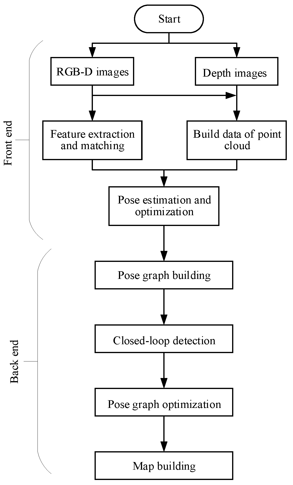
Endres et al. propose an RGB-D SLAM method in 2012 [
22]. This method divides the RGB-D SLAM system into two parts: front-end and back-end. The front-end is responsible for establishing the spatial transformation relationship by processing sensor information, and the back-end is responsible for reducing cumulative error by graph optimization. This method uses SIFT, SURF (speeded up robust features) [
23], and ORB (ORiented brief) algorithms [
24] to extract features, and the RANSAC algorithm to process image alignment. Unlike Henry, the ICP algorithm is not used for image alignment, and then the g
o (general graph optimization) algorithm [
25] is used for graph optimization. Finally, the method uses the Octomap library [
26] to raster the final output point cloud map to form a grid map, which is convenient for robot navigation and localization. In addition, Endres et al. also use the location accuracy evaluation method by Sturm [
21] to verify the proposed RGB-D SLAM method.
Scherer et al. propose an RGB-D SLAM method in 2013 [
27]. This method uses the HOG-MAN algorithm [
28] to optimize the graph in the back end of RGB-D SLAM, and finally construct a 3D environment map. The RGB-D SLAM method proposed by Scherer et al. in 2013 does not splice each frame of the image. Instead, it uses the Harris scoring function constructed by the number of FAST corner points as the criterion to filter the key frames, and then splicing these key frames. This method uses the BA (bundle adjustment) algorithm combined with the depth information to perform image registration on key frames.
Quang et al. make some improvements to the RGB-D SLAM method in 2015 [
29]. This method only uses the RANSAC algorithm to establish the spatial transformation relationship, and then selects the key frames for image mosaic according to the magnitude of the transformation amplitude, instead of splicing each image, so as to reduce the cumulative error and improve the position accuracy of RGB-D SLAM system.
In 2011, Neumann et al. [
30] use a GPU (graphics processing unit) to improve the processing efficiency of the RGB-D SLAM system. This method puts the process of processing point cloud data using the ICP algorithm on the GPU unit, and the experimental results prove the processing on the GPU unit. The time is less than 20 ms, which can greatly reduce the computational cost of the RGB-D SLAM system.
Lee et al. [
31] propose a real-time RGB-D SLAM method based on GPU unit in 2012. This method uses the GPU unit to realize the parallelization of feature extraction and pose optimization to improve computational efficiency. In 2015, to solve the problem that it is difficult to match visual features in the simple steps by using visual sensors alone, Bmnetto et al. [
32] construct a system combining vision and inertial measurement in 2015 and validate the effectiveness of this method by experiments. Aiming at the problem of less texture and ambiguous environment, Qayyum et al. [
33] propose an RGB-D SLAM method combining the inertial navigation information in 2017, which can effectively reduce the error of pose estimation.
In 2018, Zhang et al. [
34] propose a surface closed-loop visual SLAM framework (LoopSmart). It combines sparse feature matching and dense surface alignment strategies. Sparse feature matching is used for visual odometers and for camera global pose fine-tuning when dense loops are detected, while dense alignment is the method of large loops and solving surface mismatch problems. The framework is based on the tracking module of ORB-SLAM2 [
35] and the intensive model fusion strategy is based on the surface model. They have performed a lot of experimental verification on different data sets and have a good effect on camera trajectory and 3D reconstruction accuracy.
In 2018, Ylimäki et al. [
36] propose a method to deal with outliers even in the case of very serious registration error, aiming at the problem that the depth images of the RGB-D sensor will produce noise and lead to poor initial registration. This method is robust to abnormal and wrong depth measurements, as well as significant depth map registration errors caused by an inaccurate initial camera pose.
For dense RGB-D SLAM, previous work has focused on BA(Bundle adjustment) approximations. In 2019, Schöps et al. [
37] present a novel RGB-D SLAM method with a real-time direct BA back-end, which allows one to use rich information during global optimization, resulting in very accurate trajectories.
After recent years of development, RGB-D SLAM technology tends to be mature [
38,
39] and has achieved good experimental results. However, the RGB-D SLAM algorithm still has some shortcomings. The advantages and disadvantages of the RGB-D SLAM algorithm are listed in
Table 1.
In view of the two disadvantages of (1) and (2), we propose the improvement of the original RGB-D SLAM in
Section 4. For the third disadvantage, in the construction of a large-scale scene map, with the continuous operation of robots in an unknown environment, more and more data are collected by the RGB-D SLAM system, and the amount of information that needs to be processed by its back end will increase correspondingly. Especially in the later stages of reconstructing 3D maps of larger scenes in RGB-D SLAM system, the amount of information needed to be processed in the back end will be doubled, seriously affecting the real-time performance of the system. So, the algorithm in this paper unloads the back-end computation to the cloud in the 3D reconstruction system for improving the real-time performance of the system.
2.2. “Cloud+Robot” SLAM
The development and current status of robot SLAM are described above. The introduction of cloud computing is of great significance to SLAM. On the one hand, the massive computing storage resources of the cloud itself are sufficient to deal with most SLAM algorithms. On the other hand, placing the SLAM module in the cloud instead of the robot side can greatly alleviate the resource burden of the robot and eliminate the cumbersome and expensive deployment work. In the combination of cloud robot technology and SLAM, many researchers have also proposed a number of different frameworks, such as DAvinCi [
40], Rapyuta [
41], and C
TAM [
42].
2.2.1. DAvinCi
DAvinCi [
40] is one of the earliest software frameworks to enhance the capabilities of robots using cloud robotics. It aims to enhance the capability of robots in large and complex environments by utilizing the powerful computing and parallel processing capabilities of the cloud. In the actual demonstration, DAvinCi uses FastSLAM in SLAM to verify the feasibility of this architecture in paper [
40], which proves that the cloud + robot can improve the performance of the robot, and it also proves that the computational storage resources required by SLAM are non-negligible or even unbearable burdens for the robot.
The DAvinCi framework [
43] has some limitations. First of all, the robot in its architecture is passively using the cloud to improve performance rather than actively using the cloud according to its needs. It is necessary to set the scene and action of its use in the cloud beforehand, which is obviously impossible for the task of robots in large and complex environments. So, it determines that the DAvinCi framework cannot meet the current needs of robots. Secondly, its cloud architecture Hadoop has good performance in parallel processing tasks and computing but it has no obvious effect on tasks that cannot be processed in parallel. For SLAM, it is difficult to adapt to the different SLAM algorithms.
2.2.2. Rapyuta
Rapyuta is the “brain” part of the European RoboEarth Project, which aims to improve robotic capabilities through a series of advantages of the cloud. Its core technology is to use LXC (Linux container) technology to build a virtual machine corresponding to a robot in the cloud. In paper [
44], the SLAM experiment is performed using Rapyuta to verify the support and enhancement of the cloud for the low-cost robot SLAM under the Rapyuta framework.
Rapyuta’s main advantage [
45] is that, first of all, its architecture is a typical PaaS (platform as a service) architecture, which provides the cloud function as a service to the robot. Robots have full rights of autonomous mobilization and use. Secondly, Rapyuta ensures strong support for robots with different shapes, hardware, and systems, and conforms to the characteristics of a unified platform.
Rapyuta has some limitations. Considering the task requirements of current robots, the tasks faced by robots are not single functional requirements, but a series of complex functions. Therefore, it is often necessary to run multiple different functional nodes on a virtual machine corresponding to a robot. At the same time, there is a wide gap between the resources and resource categories required by these functional nodes, which makes it necessary to consider the needs of different robots when building virtual machines for robots and change according to the different tasks of robots. Therefore, for the cloud, the robot-based computing unit is not conducive to cloud resource management.
2.2.3. CTAM
C
TAM is a “cloud + robot” framework for collaborative mapping, which adapts to the cooperative SLAM problem [
46,
47]. It aims to solve the problems of map operation, map reuse, map expansion, and multi-machine collaborative mapping in SLAM through the resource advantages of the cloud. C
TAM is based on PTAM (parallel tracking and mapping) method [
48]. PTAM is based on the classical SLAM algorithm. According to the characteristics of the 3D map, the two processes of tracking and mapping are separated into two parallel steps from each iteration. On the one hand, the mapping side extracts common feature points through the observed images to form a whole image. On the other hand, the observer obtains the current position information by matching the current image with the whole image. C
TAM chooses to put the composition part of PTAM into the cloud because it consumes more resources. Thus, the efficiency of SLAM is improved.
Based on the SLAM algorithm in the cloud, CTAM utilizes the separation of the PTAM mapping process and robot localization. On the basis of single machine SLAM, multi-machine collaborative mapping can be constructed by map fusion in the cloud. At the same time, the storage resources in the cloud are used to store the maps that have been constructed. When there are new mapping tasks, the automatic search and matching will be carried out to minimize redundant tasks. This process is called map reuse. If the machine acquires information that does not match the original map or information that is not included in the original map on the basis of matching the existing map, the cloud will update the map according to the new observation information. This process is called map extension.
The advantage of C
TAM architecture is that it makes full use of the cloud, and uses the PTAM method of 3D mapping to propose a more successful “cloud + robot” architecture and the corresponding processing methods are provided for various requirements in the SLAM process. In the paper [
42], a detailed experimental verification of its various functions is carried out, which proves the availability and efficiency of its architecture. The ideas and methods of dealing with various SLAM scenario functions are worth reading for reference.
Its limitation [
49] is that only one method of 3D mapping is proposed to solve the cloud problem. Robot SLAM has different optimal methods and algorithms according to its different service function scenarios. At the same time, the map’s needs will vary with the environment and people. C
TAM is obviously difficult to provide a general solution to the SLAM problem cloud.
2.2.4. Comparison of Different Platforms
Each of these frameworks has its own advantages and disadvantages, as shown in
Table 2.
There are connections and differences in working principles among different cloud architectures. Each framework used a different set of protocols that allow robots to offload the computation to the cloud. The Rapyuta framework is a more flexible framework than the other. Due to the open-source implementation of the Rapyuta framework, it can be extended to other robot functionalities easily. The DAvinCi framework has more advantages in parallelism, while the CTAM framework is more suitable for large data storage and low bandwidth. As this paper discusses the SLAM issue, CTAM framework is chosen as the cloud platform.


