Minimization of the Settling Time of Variable Area Flowmeters
Abstract
:1. Introduction
2. Materials and Methods
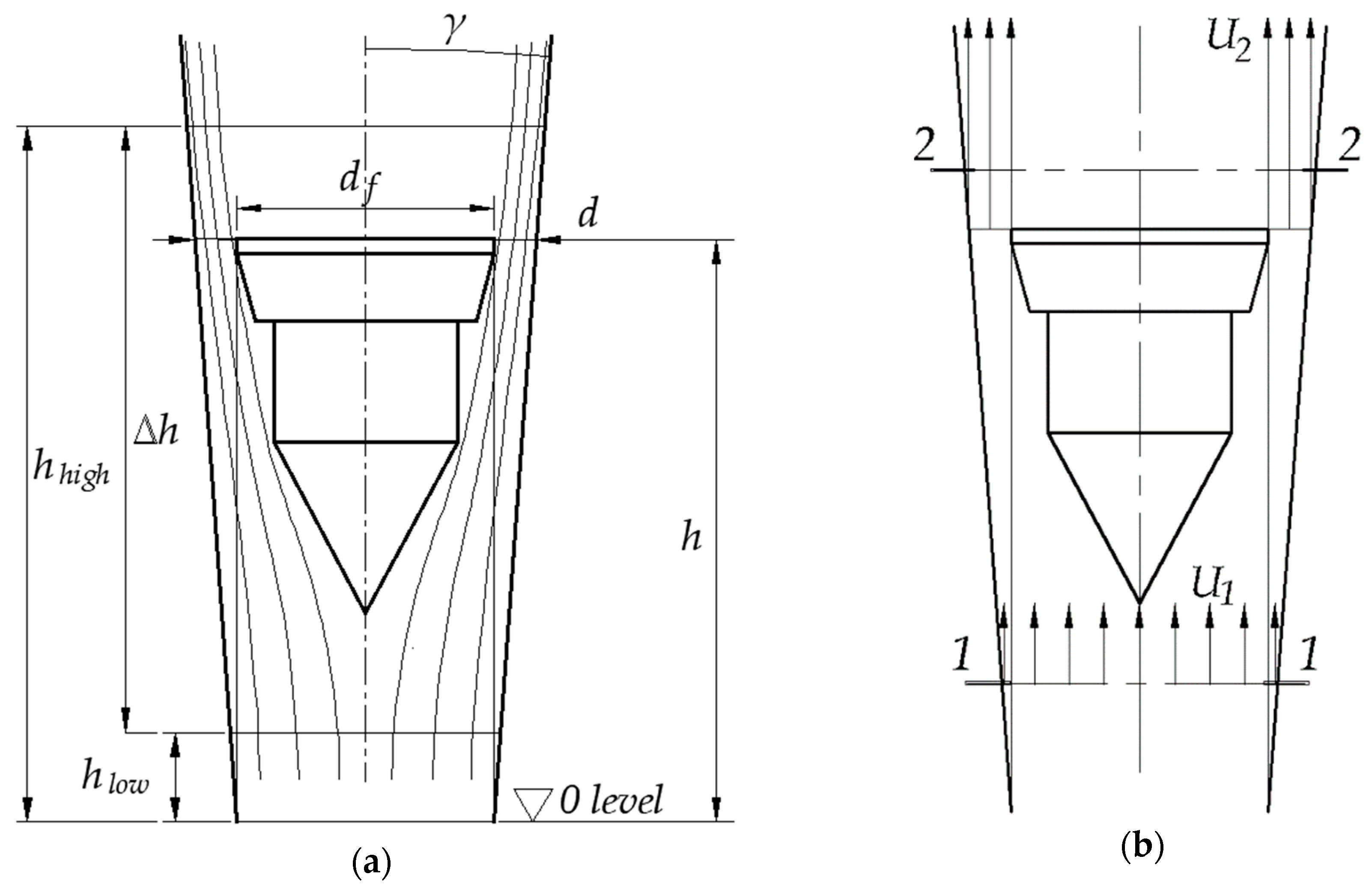
2.1. VA Flowmeter Characteristics in Steady State
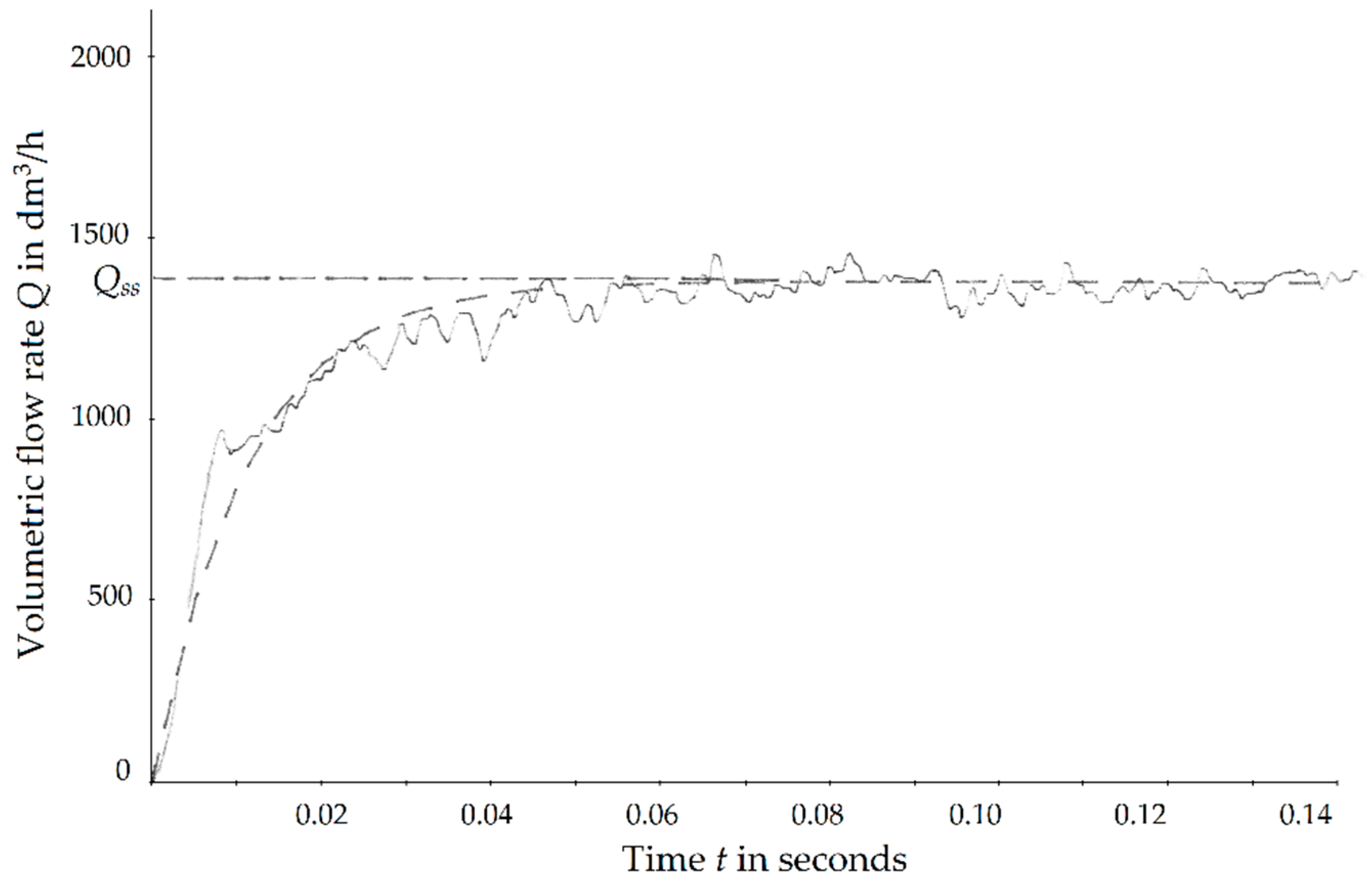
2.2. VA Behavior During Transient
2.3. Validation of the Transient Equation
2.4. Optimization
3. Results and Discussions
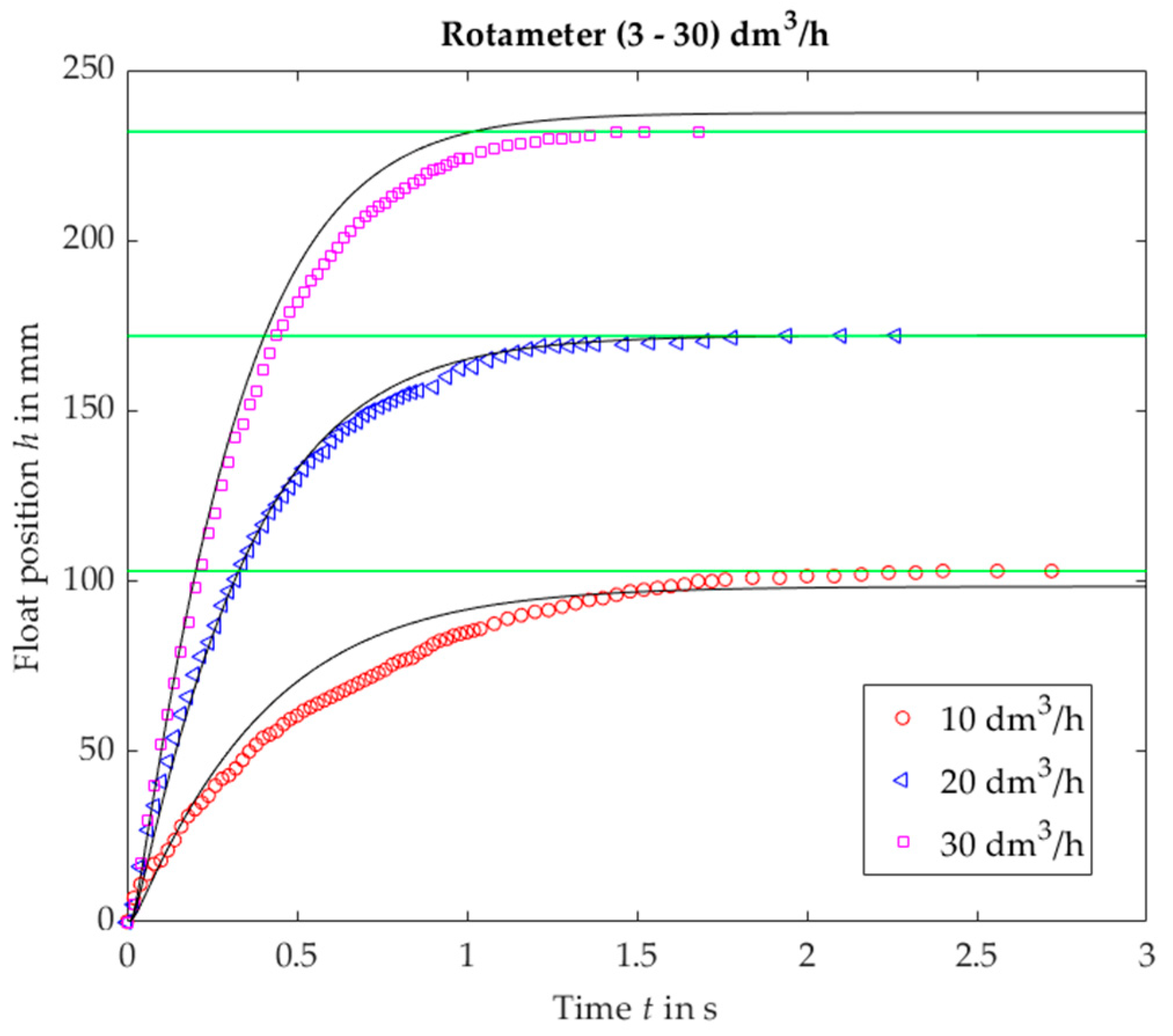
3.1. Validation of the Transient Equation
3.2. Optimization of VA Flowmeters
4. Conclusions
Author Contributions
Funding
Conflicts of Interest
Nomenclature
| A = π/4(d2 − df2) (m2) | Area of the annulus between tube and float |
| A2 = Cc·A (m2) | Area of the narrowest part of the stream |
| Af = πdf2/4 (m2) | Area of the float |
| ci | Sensitivity coefficient |
| C (-) | Flow coefficient |
| CC (-) | Contraction coefficient |
| d (m) | Tube diameter corresponding to the current float postition |
| df (m) | Float diameter |
| dhigh (m) | Tube diameter at the height corresponding to the upper flow rate limit Qmax |
| dlow (m) | Tube diameter at the height corresponding to the lower flow rate limit Qmin |
| D, E (-) | Coefficients of a curve approximating C(Re) |
| FA (N) | Active force |
| FR (N) | Restoring force |
| g (m/s2) | Acceleration due to gravity |
| h (m) | Position of the float related to the zero level |
| hss (m) | Float position in steady state |
| k (-) | Number of points (vertices) used in the optimization procedure |
| li | Lower bound for optimized parameter |
| m (kg) | Float mass |
| n (-) | Number of optimized parameters |
| p1 (Pa) | Pressure in the section where the float does not yet influence the flow |
| p2 (Pa) | Pressure in “vena contracta” |
| Q (m3/h) | Volumetric flow rate |
| Q′ (m3/h) | Additional volumetric flow rate due to movement of the float |
| Qmax (m3/h) | Upper flow limit |
| Qmin (m3/h) | Lower flow limit |
| Qss (m3/h) | Volumetric flow rate in steady state |
| r (-) | Random number |
| Re (-) | Reynolds number |
| t (s) | Time |
| t0.97 (s) | Settling time |
| ui | Upper bound for optimized parameter |
| u (x) | Standard uncertainty |
| uc (x) | Combined uncertainty |
| U95 (x) | Expanded uncertainty at 95% confidence level |
| U (m/s) | Fluid velocity |
| U1 (m/s) | Fluid velocity in the section where the float does not yet influence the flow |
| U2 (m/s) | Fluid velocity in “vena contracta” |
| U′ (m/s) | Additional fluid velocity due to movement of the float |
| Vf (m3) | Float volume |
| xi | Estimate of input quantity in a measurement process |
| Xi | Input quantity in a measurement process |
| y | Estimate of output quantity in a measurement process |
| Y | Output quantity in a measurement process |
| α (-) | Reflection coefficient |
| γ (rad) | Tapering angle |
| Δh (m) | Distance between dlow and dhigh |
| Δxi | Increment in the estimate of input quantity xi |
| Δy | Increment in the estimate of output quantity y caused by Δxi |
| ν (Pa·s) | Kinematic viscosity of the fluid |
| ρ (kg/m3) | Fluid density |
| ρf (kg/m3) | Float density |
| ω | Optimized parameter |
Appendix A. Description of the Optimization Algorithm

Appendix B. Uncertainty Evaluation
Appendix B.1. Uncertainty of Calculations
| xi | Δxi | df in mm | dhigh in mm | dlow in mm | Δh in mm | m in g∙10−2 | ρ in kg/m3 | υ in m2/s·10−5 | Q in dm3/h | C | h increment in m | ci |
|---|---|---|---|---|---|---|---|---|---|---|---|---|
| df | 0.01 | 4.00 | 4.31 | 4.08 | 236 | 5.38 | 1.293 | 1.45 | 0.01 | 0.2905 | 0.00014 | 0.014 |
| dh | 0.01 | 3.99 | 4.32 | 4.08 | 236 | 5.38 | 1.293 | 1.45 | 0.01 | 0.2905 | −0.00791 | −0.791 |
| dl | 0.01 | 3.99 | 4.31 | 4.09 | 236 | 5.38 | 1.293 | 1.45 | 0.01 | 0.2905 | 0.00876 | 0.876 |
| Δh | 1 | 3.99 | 4.31 | 4.08 | 237 | 5.38 | 1.293 | 1.45 | 0.01 | 0.2905 | 0.0008 | 0.0008 |
| m | 0.01 | 3.99 | 4.31 | 4.08 | 236 | 5.39 | 1.293 | 1.45 | 0.01 | 0.2905 | −0.00172 | −0.172 |
| ρ | 0.01 | 3.99 | 4.31 | 4.08 | 236 | 5.38 | 1.303 | 1.45 | 0.01 | 0.2905 | 0.00072 | 0.072 |
| ν | 0.01 | 3.99 | 4.31 | 4.08 | 236 | 5.38 | 1.293 | 1.46 | 0.01 | 0.2905 | 0.00075 | 0.075 |
| Q | 0.1 | 3.99 | 4.31 | 4.08 | 236 | 5.38 | 1.293 | 1.45 | 10.1 | 0.2905 | 0.0079 | 7.9 |
| C | 0.01 | 3.99 | 4.31 | 4.08 | 236 | 5.38 | 1.293 | 1.45 | 0.01 | 0.3005 | −0.00629 | −0.629 |
| Input Quantity xi | Nominal Value | Standard Uncertainty u(xi) | Unit | Sensitivity Coefficient ci | Unit | (ci·u(xi))2 in m2 |
|---|---|---|---|---|---|---|
| df | 3.99 × 10⁻³ | 0.0075 | mm | 0.014 | m/mm | 1.1 × 10⁻⁸ |
| dhigh | 4.31 × 10⁻³ | 0.0075 | m | −0.791 | m/mm | 3.52 × 10⁻⁵ |
| dlow | 4.08 × 10⁻³ | 0.0075 | m | 0.876 | m/mm | 4.32 × 10⁻⁵ |
| Δh | 236 × 10−3 | 0.5 | m | 0.0008 | m/mm | 1.6 × 10⁻⁷ |
| m | 5.38 × 10⁻³ | 0.001 | kg | −0.172 | m/kg | 2.96 × 10⁻⁸ |
| ρ | 1.293 | 0.0025 | kg/m3 | 0.072 | m/(kg/m3) | 3.24 × 10⁻⁸ |
| ν | 1.25 | 0.02 | m2/s × 10−5 | 0.075 | m/(m2/s × 10−5) | 2.25 × 10⁻¹² |
| Q | 0.01 | 0.0000125 | m3/h | 7.9 | m/(m3/h) | 9.75 × 10⁻⁹ |
| C | 0.2905 | 0.0025 | - | −0.629 | m | 2.47 × 10⁻⁶ |
| Σ(ciu(xi))2 | m2 | 8.11 × 10⁻⁵ |
Appendix B.2. Uncertainty of Experiments
References
- Martin, J.J. Calibration of rotameters. Chem. Eng. Prog. 1949, 45, 338–342. [Google Scholar]
- Lutz, K. Die Berechnung des Schwebekörper-Durchflußmessers. Regelungstechn 1959, 7, 355–360. [Google Scholar]
- Shafer, M.R.; Van Lone, B. Correcting for Density and Viscosity of Incompressible Fluids in Float-Type Flowmeters. Res. NBS 1951, 47, 227. [Google Scholar] [CrossRef]
- Jiang, W.; Zhang, T.; Xu, Y.; Wang, H.; Guo, X.; Lei, J.; Sang, P. The effects of fluid viscosity on the orifice rotameter. Meas. Sci. Rev. 2016, 16, 87–95. [Google Scholar] [CrossRef]
- Singh, S.N.; Gandhi, B.K.; Seshadri, V.; Chauhan, V.S. Design of a bluff body for development of variable area orifice-meter. Flow Meas. Instrum. 2004, 15, 97–103. [Google Scholar] [CrossRef]
- Mandal, N.; Kumar, B.; Sarkar, R.; Bera, S.C. Design of a flow transmitter using an improved inductance bridge network and rotameter as sensor. IEEE Trans. Instrum. Meas. 2014, 63, 3127–3136. [Google Scholar] [CrossRef]
- Ahn, H.J.; Kim, K.R. 2D Hall sensor array for measuring the position of a magnet matrix. Int. J. Precis. Eng. Manuf. Technol. 2014, 1, 125–129. [Google Scholar] [CrossRef]
- Garcia-Diego, F.-J.; Sánchez-Quinche, A.; Merello, P.; Beltrán, P.; Peris, C. Array of hall effect sensors for linear positioning of a magnet independently of its strength variation. A case study: Monitoring milk yield during milking in goats. Sensors 2013, 13, 8000–8012. [Google Scholar] [CrossRef] [PubMed]
- Mo, B.; Jiang, F.Y.; Zhang, H.X. The Electronic Part of the Metal Tube Rotameter. Appl. Mechan. Mater. 2013, 419, 661–666. [Google Scholar] [CrossRef]
- Liu, C.Y.; Lua, A.C.; Chan, W.K.; Wong, Y.W. Theoretical and experimental investigations of a capacitance variable area flowmeter. Trans. Inst. Meas. Control 1995, 17, 84–89. [Google Scholar] [CrossRef]
- Baker, R.C.; Sorbie, I. A review of the impact of component variation in the manufacturing process on variable area (VA) flowmeter performance. Flow Meas. Instrum. 2001, 12, 101–112. [Google Scholar] [CrossRef]
- Baker, R.C. The impact of component variation in the manufacturing process on variable area (VA) flowmeter performance. Flow Meas. Instrum. 2004, 15, 207–213. [Google Scholar] [CrossRef]
- Ligeza, P. Model and Simulation Studies of the Method for Optimization of Dynamic Properties of Tachometric Anemometers. Sensors 2018, 18, 2677. [Google Scholar] [CrossRef] [PubMed]
- Harrison, G.S.; Armstrong, W.D. The frequency response of rotameters. Chem. Eng. Sci. 1960, 12, 253–259. [Google Scholar] [CrossRef]
- Dijstelbergen, H.H. Rotameter dynamics. Chem. Eng. Sci. 1964, 19, 853–865. [Google Scholar] [CrossRef]
- Ury, J.F. The Pulsation Error of Rotameter. Isr. J. Teh. 1963, 1, 19–31. [Google Scholar]
- International Organization for Standardization. Measurement of Fluid Flow in Closed Conduits. Guidelines on the Effects of Flow Pulsations on Flow-Measurement Instruments; ISO/TR 3313; International Organization for Standardization: Geneva, Switzerland, 2018. [Google Scholar]
- Turkowski, M.; Szufleński, P. New criteria for the experimental validation of CFD simulations. Flow Meas. Instrum. 2013, 34, 1–10. [Google Scholar] [CrossRef]
- Korobiichuk, I.; Bezvesilna, O.; Ilchenko, A.; Shadura, V.; Michał, N.; Szewczyk, R. A mathematical model of the thermo-anemometric flowmeter. Sensors 2015, 15, 22899–22913. [Google Scholar] [CrossRef] [PubMed]
- JCfGi, M. Evaluation of Measurement Data—Guide to the Expression of Uncertainty in Measurement. Available online: https://www.bipm.org/utils/common/documents/jcgm/JCGM_100_2008_E.pdf (accessed on 27 January 2019).
- International Organization for Standardization. Measurement of Fluid Flow—Procedures for the Evaluation of Uncertainties; ISO 5168:2005; International Organization for Standardization: Geneva, Switzerland, 2005. [Google Scholar]


| VA no. | Nominal Range dm3/h | Float Shape | df mm | dlow mm | dhigh mm | Δh mm | mf g | D | E |
|---|---|---|---|---|---|---|---|---|---|
| 1 | 3–30 | Plumb bob | 3.990 | 4.080 | 4.310 | 236 | 0.053 | 0.2369 | 0.0815 |
| 2 | 20–220 | Plumb bob | 4.030 | 4.130 | 4.560 | 223 | 0.381 | 0.2485 | 0.0388 |
| 3 | 100–800 | Plumb bob | 8.910 | 9.307 | 10.360 | 216 | 0.595 | 0.2132 | 0.0502 |
| 4 | 200–2200 | Plumb bob | 9.020 | 9.237 | 10.354 | 215 | 4.055 | 0.1789 | 0.0929 |
| 5 | 500–3000 | Plumb bob | 11.030 | 11.22 | 12.485 | 236 | 7.298 | 0.1444 | 0.297 |
| 6 | 25–230 | Sphere | 3.972 | 4.130 | 4.560 | 223 | 2.54 | 0.2784 | 0.0447 |
| 7 | 550–2400 | Sphere | 8.731 | 9.237 | 10.354 | 215 | 2.79 | 0.1680 | 0.1654 |
| No. | Lower Bound li | Parameter | Upper Bound ui |
|---|---|---|---|
| 1 | 4 mm | df | 25 mm |
| 2 | 0.05 mm | dlow − df | 1 mm |
| 3 | 150 mm | Δh | 400 mm |
| 4 | 0.2 g/cm3 | m/(0.697d3f) | 11 g/cm3 |
| VA no. | Nominal Range in dm3/h | Float Shape | df in mm | dlow in mm | Tube Tapering | Δh in mm | ρf in g/cm3 | t0.97 in s |
|---|---|---|---|---|---|---|---|---|
| 1 | 10–100 | Plumb bob | 4.517 | 4.818 | 0.0031 | 150 | 0.437 | 0.349 |
| 2 | 50–500 | Plumb bob | 10.21 | 10.58 | 0.0066 | 150 | 0.258 | 0.336 |
| 3 | 200–2000 | Plumb bob | 20.53 | 20.88 | 0.0088 | 150 | 0.355 | 0.326 |
| No. | Δh in mm | dlow in mm | dlow − df in mm | ρf in g/cm3 | Theoretical Values | Experimental Values | |||||
|---|---|---|---|---|---|---|---|---|---|---|---|
| Qmin in dm3/h | Qmax in dm3/h | t0.97 in s | Qmin in dm3/h | Qmax in dm3/h | t0.97 in s | Overshoot in %hss | |||||
| 1 | 2 | 3 | 4 | 5 | 6 | 7 | 8 | 9 | 10 | 11 | 12 |
| 1 | 236 | 4.080 | 0.091 | 4.098 | 7.5 | 73 | 0.372 | 8.2 | 62 | 0.35 | 2.0 |
| 2 | 223 | 4.130 | 0.106 | 1.235 | 2.6 | 68 | 0.341 | 3.2 | 64 | 0.31 | 1.9 |
| 3 | 216 | 9.307 | 0.339 | 0.299 | 37 | 361 | 0.341 | 46 | 384 | 0.32 | 2.1 |
| 4 | 215 | 9.237 | 0.381 | 0.252 | 38 | 352 | 0.345 | 37 | 361 | 0.33 | 2.3 |
| 5 | 236 | 11.22 | 0.402 | 0.252 | 60 | 554 | 0.356 | 72 | 566 | 0.36 | 1.1 |
© 2019 by the authors. Licensee MDPI, Basel, Switzerland. This article is an open access article distributed under the terms and conditions of the Creative Commons Attribution (CC BY) license (http://creativecommons.org/licenses/by/4.0/).
Share and Cite
Turkowski, M.; Szczecki, A.; Szudarek, M. Minimization of the Settling Time of Variable Area Flowmeters. Sensors 2019, 19, 530. https://doi.org/10.3390/s19030530
Turkowski M, Szczecki A, Szudarek M. Minimization of the Settling Time of Variable Area Flowmeters. Sensors. 2019; 19(3):530. https://doi.org/10.3390/s19030530
Chicago/Turabian StyleTurkowski, Mateusz, Artur Szczecki, and Maciej Szudarek. 2019. "Minimization of the Settling Time of Variable Area Flowmeters" Sensors 19, no. 3: 530. https://doi.org/10.3390/s19030530
APA StyleTurkowski, M., Szczecki, A., & Szudarek, M. (2019). Minimization of the Settling Time of Variable Area Flowmeters. Sensors, 19(3), 530. https://doi.org/10.3390/s19030530


