1. Introduction
Recently, eyeblink detection has been the subject of significant attention in the human–computer interaction domain, with a considerable amount of research being conducted utilising this method, for instance, in the automobile accident prevention domain for monitoring driver fatigue and drowsiness [
1,
2,
3], the disabled assistant domain [
4] and in the healthcare domain, such as detecting computer vision syndrome [
5]. Different approaches have been adopted in these domains to detect eyeblinks. These involve employing several techniques to analyse the captured frames, such as optical flow [
6], template matching [
7] and contour analysis [
8]. These techniques generate an eyeblink waveform after analysing the captured frames, which is then post-processed to detect eyeblinks. Furthermore, these methods use a frontal-monitoring setup to observe the complete face of the participant. In our study, we focus on a video-based eye monitoring approach to eyeblink detection.
The issue of detecting eyeblinks for a VR headset has other requirements when compared to the above described methods in the mentioned domains. First, the participant is wearing a VR headset, which partially occludes the face and completely covers the eyes. Second, the monitoring camera is mounted inside the VR headset, which makes the lighting conditions of this case different from the complete face monitoring setup. Additionally, a non-frontal monitoring setup is employed to monitor the eye to avoid the occlusion of the VR headset’s display. These points make the available eyeblink datasets in the community inappropriate to train and validate our proposed approach.
A few studies have attempted to address the eyeblink detection problem in virtual reality (VR). However, at the time of conducting this study, eyeblink tracking is not standard in the current consumer versions of VR headsets, like HTC-Vive, Oculus and PlayStation, but there are many VR applications that can utilise real-time eyeblink tracking. For instance, avatars’ eyeblinks can be animated to make them more lifelike during social interaction in Immersive Virtual Environments (IVEs). Another application is repositioning and reorienting the participant imperceptibly in an IVE to tackle the locomotion issue in VR. Moreover, combining information about a participant’s head motion patterns and eyeblink frequency can be deployed to identify different types of high-level cognitive activities, such as, reading, talking or performing tasks, that require high cognitive effort [
9]. Additionally, the possibility of exposure to dry eye syndrome (eye fatigue, dryness, soreness, red-eye and headache) due to lengthy VR sessions can be monitored and thus, participant fatigue can be detected [
5].
The main objective of this study is to implement a real-time eyeblink detector able to detect eyeblinks during the closing or pause phases of the eyeblink, and before the reopening phase. This is crucial before future proposed work can be embarked upon, which is to reposition and reorient the participant in an imperceptible way during the eyeblink. The capturing device and the processing algorithm should both be fast enough to fulfil the task. The next section will explain some eyeblink terminology before a review of the related research is presented.
Eyeblinks and Blinking Kinematics
An eyeblink is defined as “a temporary closure of both eyes, involving movements of the upper and lower eyelids” [
10] (p. 111). They play an important role in the preservation of the eye’s ocular surface integrity. Previous studies have divided eyeblinks into three different phases: the closing phase, closed or pause phase and the reopening phase [
11,
12], as shown in
Figure 1.
There are three different kinds of blinking that can occur: a spontaneous blink, which occurs unintentionally; a voluntary blink, which occurs consciously and lasts longer than spontaneous blinks; and a reflex blink, which occurs unconsciously due to external triggers, for instance, a puff of air in front of the eye, strong sound or light. Reflexive eyeblinks can last for a shorter duration compared to voluntary and spontaneous blinks [
11,
12,
13]. The foremost were excluded from this study, because they are triggered at irregular intervals and are caused by an external stimulus. The blink rate is expressed as the mean rate of eyeblinks per minute. A healthy adult blinks roughly 10 to 20 blinks min
−1 [
13,
14]; each eyeblink can last between 75 and 400 ms [
13,
15,
16]. This range includes spontaneous and reflexive eyeblink classes. On the other hand, the volunteer eyeblinks have no defined duration. A few studies have investigated the development of blinking activity according to age [
17,
18,
19], finding an increasing in eyeblink rate in children up to adolescence [
17], while this becomes stabilised in adulthood [
14,
18]. In other studies, the eyeblink rate in elderly subjects was found to show no significant difference when compared to younger adult subjects [
14,
18,
19,
20]. During work conducted by Bologna–Agostino et al. [
11], the kinematic variables of voluntary and spontaneous eyeblinks for healthy subjects were observed.
Table 1 shows some of these variables, which are closing, pause and reopening durations for voluntary and spontaneous eyeblinks. In
Section 2, several eyeblink detection methodologies and other related studies are briefly reviewed.
2. Related Studies
Many approaches have been developed to detect eyeblinks for different applications in the domain of human–computer interaction and they can be divided into three major categories based on the data acquisition method. Approaches in the first category utilise physiological measures [
21,
22], for instance, employing electro-encephalography (EEG), or electro-oculogram (EOG) [
23,
24]. The approaches in the second category utilise an optical proximity sensor to detect eyeblinks. For instance, a study conducted by Ishimaru et al. [
9] focused on combining head motion patterns and eyeblink frequency. This information can be used to distinguish different types of high-level activities like reading, watching TV, talking and solving a mathematical problem. In this study, eyeblink frequency was estimated using the Google glass proximity sensor, which detects eyelid closure. As mentioned earlier, the approaches in the first and second categories are beyond the scope of this paper.
The approaches in the third category utilise image sensors to monitor the region of interest (the eye) to identify eyeblinks. Furthermore, methods are deployed to classify eye state (open or closed). For instance, Al-gawwam [
25] utilised an image sensor (camera) to track the facial landmarks’ positions to localise the eyes and eyelid contours. Later, the vertical distance between the upper and the lower eyelids was estimated after signal prefiltering using a Savitzky–Golay filter to improve signal-to-noise ratio (SNR). A finite state machine (FSM) was used to distinguish between false and true blink detection based on blink duration. Another method was proposed by Fogelton [
6], which was based on motion vector analysis. The proposed approach generates an eyeblink signal based on the vertical component of the calculated motion vector at the eye region. A finite state machine was used for decision making to identify eyeblinks. The performance of the automatic eyeblink detection method was good (95.8% and 91.7% for precision and recall, respectively). However, the author did not mention how the values of eyeblink detection threshold were estimated, and how the proposed approach selects the proper detection threshold from these values. Additionally, the processing time for a single frame was around 20 milliseconds, which makes this method inadequate for our application. Another approach was proposed by Królak [
7], which detects voluntary eyeblinks based on time constraints. The method utilises a Haar-like feature classifier to localise the face and the eye in the captured image. In the next step, an eyeblink signal is generated by using cross-correlation with an open eye template image over time. By comparing the signal with a predefined detection threshold, it is possible to detect eyeblinks. However, the processing time required for each frame is quite long (156 ms for 320 × 240 pixels frame size, for only face and eye localisation). Moreover, the author did not show how the eyeblink detection threshold value had been calculated.
Likewise, during a study conducted by Ivleva [
26], an eyeblink detector was implemented using a light-dependent resistor (LDR) and green light-emitting diode (LED), which detects eyelid closure, thus indicating eyeblinks. However, the proposed method suffers from a major drawback, which is the low accuracy and high rate of false positive detections due to using a Fixed LDR for eyeblink detection. Furthermore, the paper did not provide any evaluation of the performance of the eyeblink detection method.
A considerable amount of research has been carried out related to head-mounted eye tracking. For instance, in a study conducted by Fuhl et al. [
27], a new method for identifying the eyelid and estimating the eye aperture was proposed. The eye aperture was measure by approximating the lower and the upper eyelids using oriented edges. Furthermore, during the study, a new dataset was collected to validate the proposed approach, which has been published online for validation of similar methods in future studies. In another study conducted by Fuhl at el. [
28] an eyeblink detection method for head-mounted eye-trackers was put forward, which is brightness and motion-based. The proposed approach does not utilise pupil or eye localisation or edge detection. It is based on the following assumptions: the pupil is dark, and it gets fully or partially occluded by the eyelid during eyeblinks. Consequently, the brightness in the captured frames will be changed. Based on these assumptions, the algorithm subtracts two sequential frames (both framed are blurred for noise reduction) to generate a features image and uses percentile values to measure its brightness. Afterwards, a sequence of successive frames determined by sliding window width is used to extract the features from the frames sequence. The proposed algorithm utilises the Random Forest Classifier [
29] for identifying eyeblinks. The approach has been validated using a challenging dataset based on a real case scenario. The author reported that its shows high detection rate of 96.3795% using the 50th percentile and a window size of 11 frames. Moreover, the algorithm is not computationally expensive. However, the proposed algorithm identifies the eyeblink after the complete blink event has already occurred. In other words, the eyeblink is identified after the reopening phase has ended. Furthermore, the algorithms in both studies used a frontal eye monitoring setup, which makes the dataset collected inappropriate for our VR application.
Most of the reviewed methods have involved employing frontal eyeblink monitoring setups using a head-mounted eye-tracker, such that the camera positioned directly above the eye do not utilise an eye localisation procedure to identify the eye in the captured frame. However, other methods monitor the whole face and require an eye localisation approach in order to localise the eye region. Nevetheless, these techniques cannot be adopted in our approach, because the VR headset covers both of the participant’s eyes. Due to the limited space inside the VR headset, it is not possible to use head-mounted eye trackers combined with the VR headset. Hence, we decided to mount the monitoring camera inside the headset, but this can cause display occlusion while using the frontal eye monitoring setup. So, a non-frontal monitoring setup was deemed more appropriate for our approach. As a result, the available datasets in the community were non-applicable with our method. Additionally, eyeblink detection occurs after the reopening phase has finished, which is too late for the requirement of our application. The next section discusses our proposed method and the challenges of the design in detail.
3. Design Problem Statement and Proposed Method
In VR, the participant wears a VR headset (head-mounted display, HMD) to perceive a VR experience. The design challenges of detecting eyeblinks when someone is wearing a VR headset are different when compared with the conventional methods due to eye occlusion in the former. Furthermore, in our approach, a non-frontal eye monitoring setup was used. Accordingly, frontal eyeblink detection approaches cannot be used in our implementation. In this study, the main objective behind implementing an eyeblink recognition system is to reposition and reorient the participant imperceptibly in the IVE during eyeblinks. Hence, eyeblink detection should be significantly accurate and as fast as possible so that enough time is available to change the participant’s position and orientation. However, the available eyeblink identification approaches detect eyeblinks after identifying the reopening phase, which does not give enough time to reposition or rotate the participant during eyelid closure. Consequently, the available approaches were just a starting point for developing and validating our proposed approach. Additionally, we designed the solution such that it does not require preparation or calibration each time it is started. Below is a list of the design problem statements for the proposed approach:
No calibration is required;
The sensor should be mounted inside the VR headset;
No markers and electrodes are attached to the participant’s face;
Eyeblinks are identified during the closing phase;
Processing time for a single frame is <13 milliseconds (≈73 frames per second);
A single camera should be used to capture the eye movement inside the VR headset as this will have a lower cost and require fewer computational resources.
Our proposed method utilises a high-speed USB camera equipped with an OV4689 image sensor [
30] to monitor the eye inside the VR headset. The captured real-time video stream has been processed based on the following assumptions:
In the captured video stream, there are no moving objects except for the eyelid and the ocular ball;
Eyelid movements cause the predominant amount of motion in the video stream;
The motion directions caused by eyelid closing and reopening are parallel to the vertical axis (y) in the captured video stream images;
During the pause phase of the eyeblink, the eye is fully closed.
Based on these assumptions, the proposed method calculates a motion vector between two successive frames to identify eyelid closure, thus indicating the closing phase. Afterwards, full eyelid closure is verified to identify the pause phase in order to indicate an eyeblink. Before describing the proposed methodology in detail, we explain the challenges of recognising eyeblinks in real time utilising an image sensor inside a VR headset.
3.1. Challenges of Recognising Eyeblinks for a VR Headset
We had to address several problems regarding identifying eyeblinks for VR headset, which can be summarised as follows.
3.1.1. Lighting Conditions
To obtain a clear view of the eye inside the headset, effective illumination is required and the only available visible light source inside a VR headset is the display itself. However, this is not a reliable lighting source, because the amount of luminance intensity varies according to the scene currently displayed on the headset screen. Variable illumination intensity causes the dense optical flow algorithm of Gunnar Farneback [
31] to estimate a false motion vector, because it utilises the change in pixel intensity to calculate the dense optical flow between two successive frames [
31]. Hence, an external light source is required to illuminate the eye inside the VR headset. However, using visible light for illumination will raise other problems:
Visible light will distract the participant and might affect their natural eyeblink kinematic variables;
The amount of illumination intensity will vary due to changes in the brightness intensity of the display inside the headset, which, as mentioned above, will cause distortion in the estimation motion vector between two successive frames in the video stream.
We came up with a solution of using near-infrared LEDs (λ 850 nm) [
32] as a lighting source inside the VR headset to illuminate the participant’s eyes. We also used an IR pass filter in front of the image sensor to reject the visible light caused by the VR headset’s display.
3.1.2. Eyeblink Kinematics
For real-time eyeblink detection, a closer look should be taken at the duration of the blink’s kinematic variables. As aforementioned, a complete eyeblink for healthy subjects can last between 200 and 400 milliseconds. We performed the following calculations on the data in
Table 1 to estimate the approximate percentage duration of each eyeblink phase with respect to the total duration of the eyeblink. These calculations gave a better overview of the duration of each different phase during a single eyeblink event and helped to determine the appropriate capture frame rate (FPS) required from the camera. Hence,
Table 1 can be extended, as shown in
Table 2 and its visualisation in
Figure 2, where:
Regarding the tolerance value in the total blink duration, we have simply considered the highest tolerance value, which are ±15.9 and ±13.8 ms for voluntary and spontaneous eyeblinks, respectively.
Figure 2 shows the approximate percentage duration of each eyeblink phase (regardless of the difference between the duration of each blink category) with respect to a complete single blink for both spontaneous and voluntary blinks. As can be seen, the closing and pause phases together can take around 33% to 41% of the complete eyeblink duration, which is approximately 85 and 116 milliseconds (based on the data in
Table 2) for each spontaneous and voluntary eyeblink, respectively. Additionally, spontaneous blinks had a shorter pause phase compared to other focal blink types (please refer to
Table 2 in [
11]). Therefore, in order to calculate the worst-case scenario, we considered the spontaneous eyeblink in the following calculations.
As shown in
Figure 2, the pause phase comprises about 5.3% of the total blink duration, which is 13.7 ± 3.3 milliseconds. If a camera with a 30 FPS capture rate has been utilised to track eyeblinks, it is probable that at some point it will miss the pause phase event during spontaneous blinks, because ΔT is greater than the pause phase duration:
This leads to inaccurate eyeblink tracking. It is possible to estimate approximately the minimum frame per second required (
) to capture eyeblinks more reliably based on the parameters from
Table 2 using the following equation:
where, Δ
Tminimum is the minimum duration between two successive captured frames, which is assumed to be equal to or less than the pause phase duration. In the next section, the system design and the proposed algorithm are discussed in more detail.
3.2. Hardware System Design
Near-infrared LEDs were used to illuminate the eye inside the VR headset, whilst a high-speed USB camera was utilised to monitor the eye. However, behind the camera lens, there was an IR-cut filter, which rejects infrared-light and thus, some modifications needed to be made. These modifications comprised the replacement of the default camera lens (100° field of view (FOV) with an IR-cut filter) with a 145° FOV no IR-cut filter, such that the sensor can be exposed to near IR light. Finally, the camera was mounted on a customised 3D printed holder so that it could be fixed securely inside the VR headset.
Figure 3 shows the modifications to the USB camera.
Regarding the implementation of the illuminance circuit of the eyeblink detector, we used three IR-LEDs TSHG6400 from Vishay [
32] to illuminate participant’s eyes inside the VR headset, with
Table 3 showing the LED’s summarised specifications. More technical specifications can be found on the official website of Vishay.
The LEDs have ±22 angle of half intensity, which makes it inefficient for illuminating near objects. Hence, the LEDs had to be diffused by sanding them with sand paper to scatter the light to achieve better illumination. The illumination intensity of the LED is powerful and, theoretically, it is possible to use one instead of three. However, due to the narrow radiation angle, it was difficult to illuminate evenly the eye without operating the LED at the maximum radiant power. This is not a desirable working point for the LED, especially as it is very close to the eye. Hence, three LEDs were used to illuminate the eye evenly and were kept running at a low operating point to avoid over-illuminating the eye. The operation point of these LEDs was 1.7 V and approximately 5 mA for each.
Figure 4 shows a schematic diagram of the illumination circuit.
3.3. Detection Algorithm
Generally, the detection algorithm comprises three different phases:
initial blink detection,
blink verification and
reopening phase detection. Two successive frames (
fn−1,
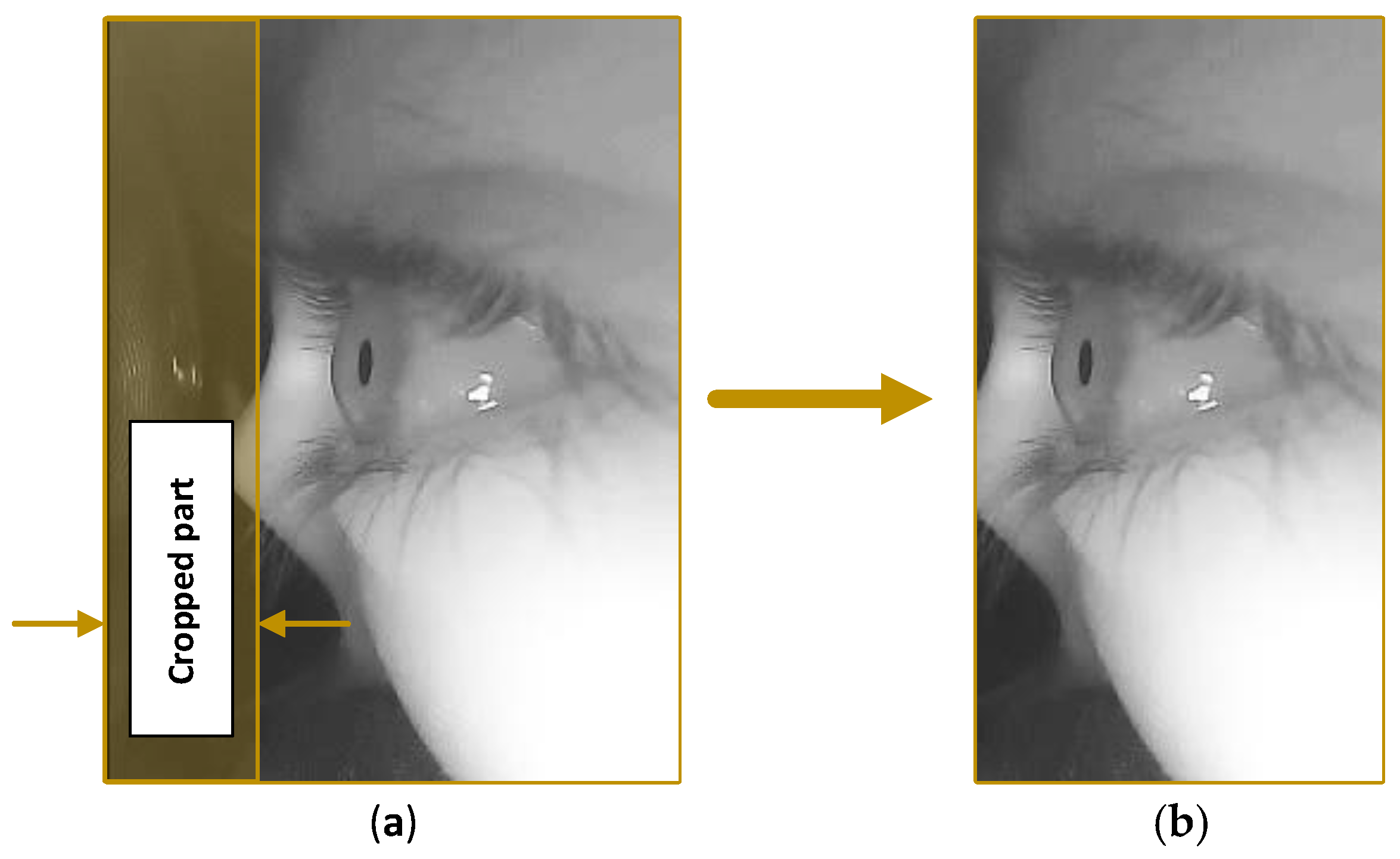
fin) were captured; the resolution of each captured frame is 240 × 320 pixels for the width and height, respectively. Because different people have different facial structure, eye shape and size, the frame orientation is in portrait layout to cover as much of the facial area as possible and to obtain a clear view of the eye. During dataset collection, we observed that the first 70 pixels do not hold any useful information, because they show the inner side of the VR headset. So, we decide to crop the first 70 pixels of the frame to improve the performance, thus reducing the frame size to 170 × 320 pixels for the width and height, respectively, as shown in
Figure 5.
3.3.1. Initial Eyeblink Detection Phase
Based on the assumption made earlier (there are no moving objects in the captured frames except the eyelid and the ocular ball), during the closing phase of the blink, the upper eyelid will move down in a rapid motion to cover the ocular ball. However, the lower eyelid is almost stationary and hence, the main motion direction between the captured frames is pointing downwards during the closing phase. During the initial blink detection phase, the detection algorithm utilised the Farneback algorithm [
31] to estimate the dense motion between the successive frames and thus, estimate the overall motion vector to detect the closing phase.
The output of the Farneback algorithm comprises two 2D arrays, both of which have the same size as the input frames. Each element in the array refers to a pixel on the captured frame, and it holds the distance of how far that pixel has moved with respect to the previous frame in pixel units. Each element in the first array holds the travelled distance along the x-axis for a particular pixel, whereas the elements held by the second array represent the travelled distance along the
y-axis for that particular pixel. Based on pixel location in the previous frame and both arrays, as calculated by the Farneback algorithm, motion vectors can be estimated. These vectors indicate motion direction between two successive frames and
Figure 6 explains how these vectors are estimated.
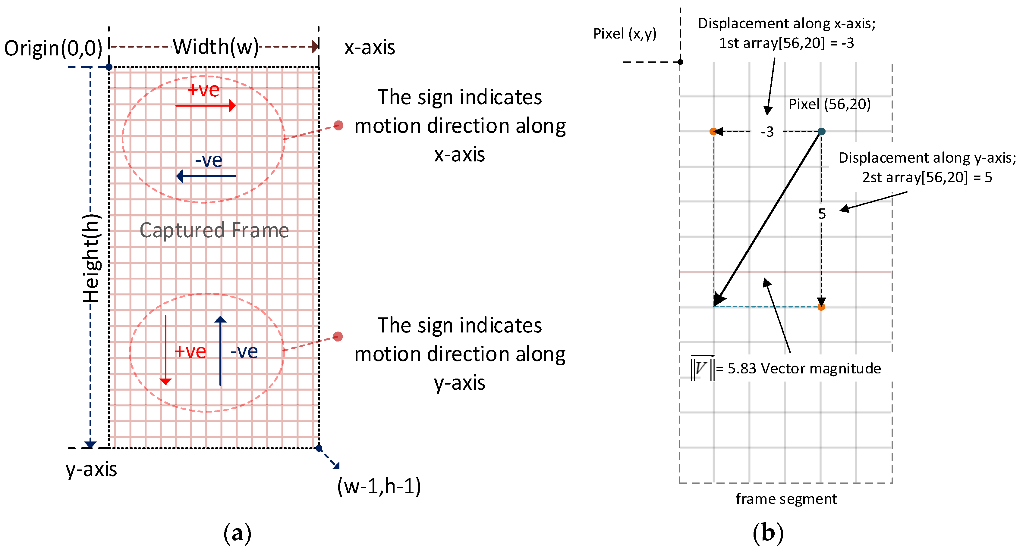
Figure 6a illustrates the 2D image coordinates, with the origin point being located at the top left corner of the frame. The
x-axis is aiming to the right and the
y-axis is aiming downwards. So, this is different to the conventional 2D Cartesian coordinate system, where the
y-axis is aiming upwards. As mentioned before, each value held by the two arrays, calculated by the Farneback algorithm, expresses how far each pixel has moved along the
x- or the
y-axis. If the value is equal to zero, this indicates that no motion occurred along the specified axis, whereas, if it is less than zero (negative), this indicates motion in the decremental direction of the axes. In contrast, values of more than zero (positive) indicate motion in the incremental direction of the axes, as shown in
Figure 6.
Figure 6b shows a segment of the captured frame, how a single vector has been calculated from the start point (pixel location) and the displacement values for the both
x and
y axes.
Because the tracked object (the eye) takes up quite a large part of the captured frame, it is not necessary to use all the pixels in the image to estimate the motion vector. A set of points are distributed evenly on the previous captured image, which act as markers indicating the starting points for a set of vectors, as shown in
Figure 7. The distance between each point to another is about “
d” pixels, for each
x- and
y-axis, as shown in
Figure 7. In our case,
d = 10 and this procedure will reduce the processing time. The total count of points “
n” is calculated as follows:
Figure 6 illustrates the process of estimating the overall motion vector from two successive frames by the Farneback algorithm. The summation of these vectors, indicating the overall motion vector
between the last successive frames, is as illustrated in the following two equations:
where:
Xw and Yh represent the drift of a predefined pixel at along the x- and y-axes, respectively, in pixel units on image coordinates. Both are estimated using the Farneback algorithm for calculating the optical flow, where is a vector describing the motion caused by the drift (Xw, Yh).
As mentioned before, during the closing phase, the major downward motion is caused by the eyelid closure. However, the saccades phenomenon (which is rapid eye movement that occurs during gaze switching between two visual fixations) could also cause motion in various directions, depending on where the fixation points are before and after the gaze switching. Accordingly, saccades can cause false positive detection. To solve this issue, the following selection criteria were applied to the vectors used to calculate the total motion vector based on the magnitude and the direction of these vectors:
Each vector with a magnitude less than two pixels will be discarded;
Each vector with a negative y-component (pointing up) will be discarded;
Each vector with a positive y-component and contributing to less than 50% of the total vector magnitude will be discarded.
After applying the selection criteria, the remaining vectors are added together to estimate the downward motion vector (DMV). If the magnitude of the downward motion vector
is above a specific threshold, this probably indicates an eyelid closing and thus, an initial blink is registered.
Method: Estimating DMV (previous frame, current frame)
- (a)
Pass frames to the Farneback algorithm to estimate the overall motion vector (previous frame, current frame). - (b)
Apply the following selection criteria:
Subtract all vectors with a magnitude <2 pixels ; Subtract all vectors that have a Y component <0 (pointing upwards); Subtract all vectors that have a Y component >0 (pointing downward) that contributes <50% of their magnitude.
|
Equation (8) describes how the DMV
is estimated.
3.3.2. Estimating the Dynamic Threshold for Eyelid Closure Detection
To achieve reliable eyelid closure detection based on DMV analysis, dynamic threshold estimation for eyelid closure is essential. The following algorithm describes how the dynamic detection threshold was calculated.
Method: Estimation of dynamic threshold for eyelid closure:
- (a)
- (b)
if the value of <= 0, this indicates the end of the closing phase and the start of the pause phase;
- ○
maximum value in the set “”; - ○
Add to the thresholds set - ○
New threshold value = finding the median value of the set;
Else, repeat the first step (a). |
represents the current frame number
represents the magnitude of the DMV for the current frame, , with respect to the previous frame,
“
X” is a set of values where each represents the magnitude of the DMV for
i-th frame where the magnitude is >0:
“
Y” represents the maximum value in the “
X” set, while
c represents the count of values in
:
represents a set of
values that have been detected during the last
n-th eyeblink:
represents the median value of the
set, while
c represents the count of values in
. The values in “
Z” set are sorted in increasing order:
In other words, the variable illustrates the maximum peak of the magnitude of the DMV during eyelid closure, while pertians to a set of maximum peaks of the last n-th eyeblink. Additionally, defines the new estimated eye closure detection threshold by calculating the median value of .
3.3.3. Eye Reopening Detection
During the reopening phase of the eyeblink, the upper eyelid will move upward to reveal the ocular ball. Accordingly, estimating the upward motion vector
will indicate the reopening phase and the following equation shows how the upward motion vector was calculated:
What follows is a description of the method utilised to estimate upward motion vector
Method: Estimating the upward motion vector (previous frame, current frame)
- a)
Pass frames to the Farneback algorithm to estimate the overall motion vector (previous frame, current frame); - b)
Apply the following selection criteria:
|
3.3.4. Localising the Eye “Region of Interest (ROI)” in the Captured Frame
Despite the fact that the image sensor was mounted directly above the eye, using a narrow FOV camera lens to avoid the eye localisation process was very difficult. This is because each participant has a different facial structure and hence, they might have a different interpupillary distance. Accordingly, they wear the VR headset differently, and during the VR session they might readjust the VR headset on their face for more comfort, which leads to misalignment between the eye and the camera. Consequently, eye localisation in our approach was inevitable. With our method, eye localisation was used to extract the eye feature from the captured frame to verify eyelid closure. The Haar cascade classifier (HCC) [
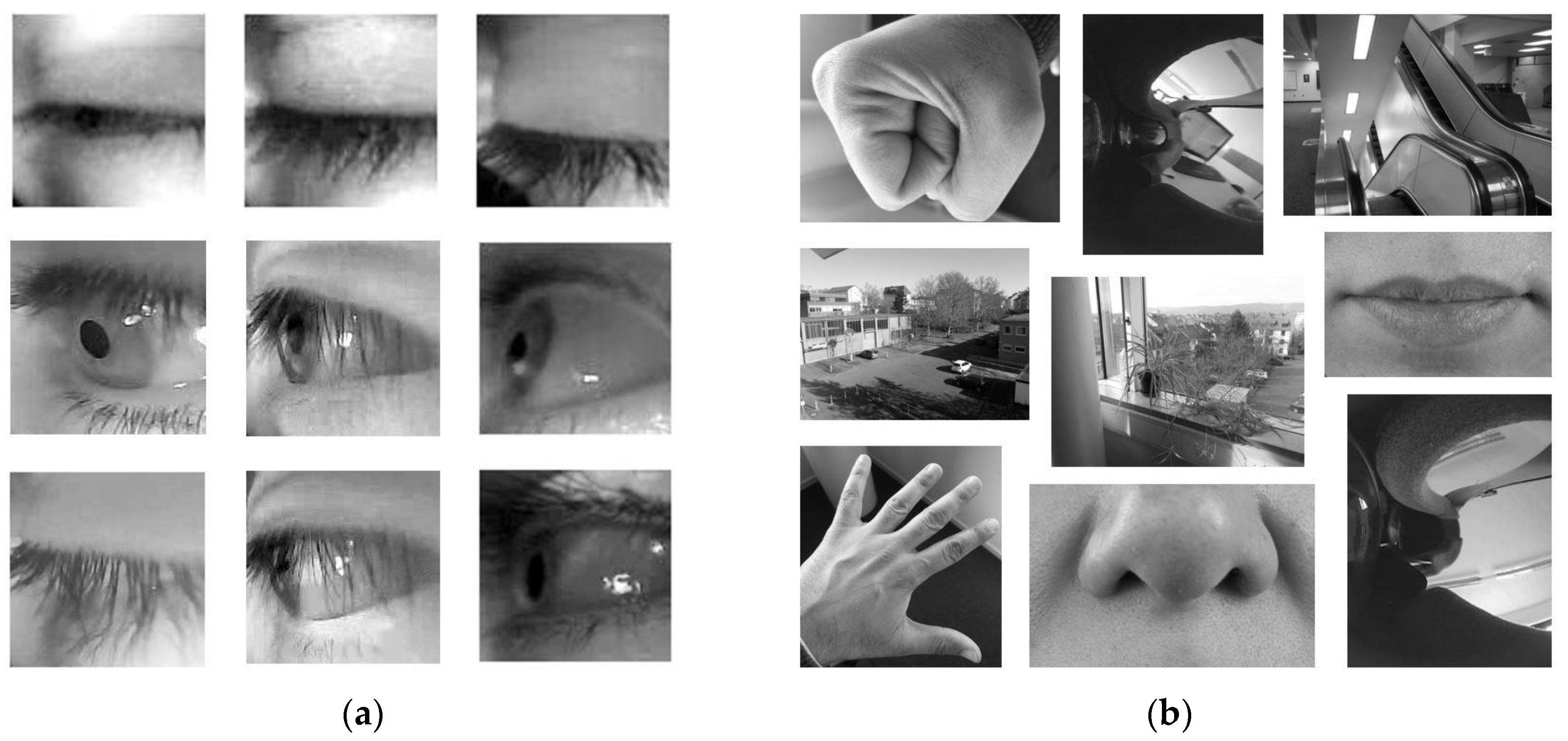
33] was utilised to identify the ROI. The HCC was trained using 670 negative images and 168 positive images. The negative images contained different random parts of the body, while the positive ones had side views of the left eye region from several participants during different eye states (eye open, closed and partially closed).
Figure 8 shows samples of the positive and negative images used in the HCC training.
The training was carried out using an open source application “Cascade Trainer GUI” [
34]. This application was used to train and test cascade classifier models. After several trials of tuning different training parameters (such as window size, number of stages and minimal hit rate), the training session took around six hours to complete. The hit rate of the HCC class of the eye localisation method was around 0.998 and 0.003 for the mean and standard deviation, respectively.
Table 4 shows statistical information about the eye localisation method hit rate. It should be noted that the dataset used for validation was not used during the training session. For more information about the Cascade Trainer GUI application please refer to [
34]. The hit rate was calculated based on Equation (14).
3.3.5. Verifying Eyelid Closure Using Cross-Correlation with a Template Image
During the next phase (blink verification), verification of eyelid closure takes place. After possible eyelid closure is detected, the localised ROI for the current frame,
fn, is checked with a template image,
t (an open eye). A normalised cross-correlation coefficient,
Q, is calculated based on Equation (15) to check the similarity between the current ROI and the eye open template image to verify eyelid closure.
where,
and represents the normalised cross-correlation coefficient,
f is the current ROI (which is the eye) and
t is the open eye template image. If the value of the cross-correlation coefficient is near 1, this indicates high similarity between the test sample and the template images. Whenever eyelid closure is verified, an eyeblink will be registered. Otherwise, a new frame will be captured, and a new detection cycle will begin. In our proposed method, we used an automatic approach to select a template image for the open eye.
Figure 9 illustrates the finite state machine (FSM) for template selection.
Figure 9 shows the FSM for automatic template selection used in our proposed approach, with there being six different states. “
S0” and “
S5” represent the initial and end state, respectively, while “
S1” represents waiting until the reopening phase is being detected. “
S2” represents time constrain, which is waiting for 500 milliseconds to elapse, a condition that will ensure the ending of all eyeblinks phases and enough time in case of double eyeblink occurrence. “
S3” pertains to checking of the eye state (open/closed) and if it is “
eye closed”, the current state will be set to “
S1”. Otherwise, the current ROI will be considered as a template image for an open eye.
3.3.6. Overall Structure of the Proposed Detection Algorithm
Figure 10 shows the structure of the eyeblink detection and eye state classification of the proposed method. Multithreading programming was utilised to reduce the time required for processing each frame. As shown in
Figure 10, estimating the motion vector was achieved on a separated thread. Simultaneously, eye localisation and eyelid closure verification were performed on another thread. Please refer to
Appendix A for more details about the proposed method in action.
Afterwards, a finite state machine was used for decision making to detect eyeblinks and classifying eye state based on the information processed by motion vector estimation, eye localisation and eyelid closure verification.
4. Finite State Machine for Eyeblink Detection and Classification
A finite state machine was defined for decision making to identify eyeblinks and classify the eye’s current state, as shown in
Figure 11.
The FSM utilises the extracted information from motion vector analysis, the Haar cascade classifier for eye localisation, and cross-correlation between the ROI and open eye template image to identify an eyeblink and classify the eye state. As shown in
Figure 11, the FSM consists of four different states: “
S0” presents the initial state, while “
S1” indicates the eye is in the open state and waiting for eyelid closure. “
S2” pertains to initial eyeblink detection and eyelid closure verification. If eyelid closure is verified, “
S2” will transit to “
S3”, which indicates a valid eyeblink, and the eye state will be classified as closed. During “
S3”, if eyelid reopening is detected, the current state will transition to “
S1”, thus indicating that the eye has reopened, and a new detection cycle will begin.
Figure 12 shows the logic diagram of the eyeblink detecting decision making process.
Figure 12 shows that there are two branches where the data could flow after the captured frame arrives, which are (1) localising the ROI and checking the eye current state, or (2) calculating the dense optical flow to estimate the motion vector. These branches are running on separated threads to reduce the processing time required for each frame. Based on the current eye state, estimating motion vector will be carried out and compared with the specified threshold. If eye state is open or not identified, the DMV will be calculated to check for eyeblink occurrence. When the magnitude of the DMV is above the specified threshold, an initial eyeblink will be registered. For the next stage, the eyelid closure will be verified with an open eye template image.
The normalised cross-correlation-coefficient will be calculated and if its value is under the specified threshold a blink will be registered, with the eye state being classified as closed. Otherwise, a new detection cycle will begin. When the eye state is closed, the reinitialisation will be triggered by estimating the UMV to calculate its magnitude. If the magnitude of the motion vector is above the specified threshold, the reopening phase will be detected. Accordingly, the eye state will be classified as open and a new detection cycle will begin. On the other hand, if the magnitude of the UMV is below this threshold, a secondary reinitialisation sub-routine will check the current ROI with an open eye template to detect the reopening phase.
5. Dataset for Training and Validation
One of the challenges that we faced due to using a non-frontal eye monitoring setup, was finding the proper dataset to train the classifier for localising the eye feature in the captured image. The available datasets in the community employed a frontal eye monitoring setup. Moreover, most of these datasets had different lighting conditions compared to the eye monitoring conditions inside a VR headset. Unfortunately, there were no datasets available for the non-frontal eye monitoring setup of a VR headset. Therefore, we collected our own dataset. A high-speed USB camera (OV4689 image sensor on board) was used with a capture frame rate between 100 and 110 fps, and the samples were recorded with an mpg2 file format with frame resolution 240 × 320 pixels for the width and height, respectively. However, this resolution was reduced further during the pre-processing to reduce the processing time required per frame. The dataset was collected from 12 different participants: two females and 10 males. The mean of their ages was 31.33 years, with standard deviation equal to 3.24. There is one video file for each participant, and they vary in duration.
Table 5 shows the statistical information for the collected samples.
The dataset comprises video-recorded samples for monitoring a participant’s eye inside the VR headset from several participants. The video stream in the dataset samples was rotated 90 degrees counterclockwise to compensate for the physical camera rotation inside the VR headset. The reason for mounting the camera 90 degrees counter-clockwise was to simplify the hardware implementation, using easier cable management inside the VR headset. Theoretically, camera orientation should not influence the algorithm’s operation. If we had taken the camera rotation into account from the beginning, we would have used the right and the left direction motion vectors for detecting eyelid closure and eyelid reopening, instead of downward and upward motion vectors, respectively. However, we chose to rotate the captured video stream to compensate for the camera’s rotation for a better understanding of the captured frames from a human perspective. During the sample collection, the participants were asked to explore their surrounding virtual environment (VE) and engage in interaction with virtual objects in the VE. We found this step necessary for distracting them from the fact that their eyes were being recorded, thereby reducing the number of possible voluntary eyeblinks.
5.1. Dataset Annotation
Dataset annotation can be defined as a high level of information added to the raw dataset as labels or tags that describe a specific role or class in the dataset. Additionally, it helps to train and validate machine-learning algorithms. The annotations file consists of an excel file with several separate sheets. Each sheet relates to a raw sample video file and the whole file represents the log of the method’s output. The following data were recorded automatically: frame number, magnitude of the downward and upward motion vectors, current eye state, detection of an eyeblink and ROI in the current frame detection. Two other columns, ground truth and the category of the detected eyeblink (true positive TP, false positive FP or false negative FN), were added to the sheet manually. Each video sample was reviewed and observed frame by frame to identify the actual eyeblinks that occurred during the recording. These annotations were used to compare the detected eyeblinks with the real ones, to evaluate the performance of the proposed method. The collected raw samples and their annotations file have been published on Mendeley database for datasets [
35] under the following
DOI “DOI: 10.17632/9yzdnng594.1”. We decided to publish them, because we believe they might be useful for future similar studies.
6. Performance Evaluation
Our evaluation procedure is based on receiver operation characteristics (ROC) analysis that has been reviewed by Fawcett [
36]. It is a method utilised to analyse and visualise classifier performance. In this study, we used this approach to validate and evaluate the performance of our method. We now explain some terminology relating to eyeblink performance evaluation. Ground truth (GT) refers to the actual eyeblinks that exist in the eyeblink signal and true positive (TP) to the detected eyeblinks that intersect (exist) with the ground truth. In contrast, false negative (FN) pertains to an eyeblink that exists in the GT, which is not detected by the algorithm, while false positive (FP) refers to an identified eyeblink that does not intersect (does not exist) with the GT. Detected blinks (DBs) represent the total count of the overall detected eyeblinks in the tested samples.
Recall describes the sensitivity or the hit rate of the proposed method, and it can be expressed by Equation (16). Precision pertains to how many selected items are relevant, representing the performance of the method, and it is expressed by Equation (17). Additionally, false discovery rate (FDR) is expressed by Equation (18) and, finally, the overall accuracy can be defined by Equation (19).
Based on Equations (16)–(19),
Table 6 shows the performance of the proposed approach.
7. Conclusions and Directions for Future Work
In this study, we proposed a method for detecting eyeblinks and classifying eye state in real time for VR headsets. Furthermore, a prototype for an eyeblink detector was implemented utilising a high-speed image sensor. The proposed method can detect eyeblinks during the closing and the pause phase of the blink. The processing time required for each frame takes 9 to 11 ms and the estimation of the motion vector takes approximately 80% of this time. Our proposed method delivers 83.9% accuracy, 91.8% for precision and 90.40% for the recall. During the study, we observed that the main reason for detecting FN blinks in the proposed method was the micro blinks that can occur during the saccades (visual gaze switching between two fixation points). Most of the time, these micro blinks are below the detection threshold. Similarly, saccades that occur along the vertical axis of the field of view can cause FP eyeblink and selecting the appropriate template for eyelid closure verification plays a big role in reducing FP eyeblinks. As a direction for future work, improving the method for automatically selecting the appropriate template image for eyelid closure verification will have a high impact on the overall performance of the algorithm.
Furthermore, we have noticed that selecting the optimal position of the camera inside the VR headset can contribute to reducing the count of false positive detections. The optimal position is using a frontal eye monitoring setup. However, in the proposed approach, a non-frontal eye monitoring setup has been used for several reasons: first, a frontal eye monitoring setup is difficult to use, because the camera might occlude the screen of the VR-headset, which will reduce the field of view. Second, the available space inside the VR headset (HTC Vive VR headset) is limited; the minimum size of the affordable high-speed USB camera (120 fps) we could access at the time of conducting this study was 28 × 28 mm for the camera board. A smaller camera size will help to monitor the eye from a better angle, thereby reducing FP detection. As mentioned before, 80% of the processing time of each frame was used for estimating the motion vector in the captured frame. We believe that the processing time can be reduced further to speed-up the eyeblink detection method, which can be achieved by using another algorithm faster than the Farneback algorithm for calculating the dense optical flow to estimate the motion vector between two successive frames. Regarding the collected dataset, it is now available online with its annotation file (please refer to
Section 5.1 regarding accessing the dataset). We hope it will be useful for future studies.
Author Contributions
Conceptualization, N.A.; methodology, N.A.; software, N.A.; validation, N.A.; formal analysis, N.A.; investigation, N.A.; resources, D.W.; data curation, N.A.; writing—original draft preparation, N.A.; writing—review and editing, N.A.; visualisation, N.A.; supervision, D.W.; project administration, N.A. The research in this work was mainly conducted by N.A., a PhD candidate in Electrical Engineering and Computer Science at the University of Kassel. The research was supervised by D.W., who provided input and feedback to improve the quality of the presented work.
Funding
This research received no external funding.
Acknowledgments
The authors would also like to thank Schiffner Sebastian and Sameer Hussam for their constructive feedbacks, thanks to Matthias Wolf for his technical support and the colleagues in the department of information technology at Kassel University, for their help during the data collecting process.
Conflicts of Interest
The authors declare no conflict of interest.
Abbreviations
The following abbreviations have been used in this paper:
| HMD | head-mounted display |
| VR | virtual reality |
| IVE | immersive virtual environment |
| EEG | electro-encephalography |
| EOG | electro-oculogram |
| FFBP | feed-forward backpropagation |
| SNR | signal-to-noise ratio |
| LDR | light-dependent resistor |
| FSM | finite state machine |
| FOV | field of view |
| FPS | frames per second |
| VE | virtual environment |
| ROI | region of interest |
| HCC | Haar cascade classifier |
| ROC | receiver operation characteristics |
| NCCC | normalised cross correlation coefficient |
| DMV | downward motion vector |
| UMV | upward motion vector |
| GT | ground truth |
| TP | true positive |
| FN | false negative |
| FP | false positive |
| DB | detected eyeblinks |
| FDR | false discovery rate |
Appendix A. Materials and Equipment
During this study, the following hardware equipment was used: IBM pc with intel core i7-7820HQ CPU at 3.6 GHz, system memory (RAM) 16 gigabyte and NVIDIA GeForce GTX780. For the display, the virtual environment HTC-Vive VR headset was utilised. For monitoring the eye inside the VR headset, a high-speed USB camera from Kayeton™ with a resolution of 640Width × 360Height pixels at 120 fps capture capability was used. Regarding the software implementation during the study, Microsoft Visual Studio 2015 was used as programming API with Accord.net framework for image acquisition and processing. Unity game engine was used to implement the virtual environment. The implemented application employed to process the captured video stream localises the eye, identifies the eyeblinks and classifies the eye state.
The evaluation results will be sent by the application to the Unity game engine via an Ethernet socket using the home IP address (127.0.0.1).
Figure A1 shows the proposed method that has been implemented with Microsoft Visual Studio to process the captured video stream in action.
Figure A1 shows the GUI of the eyeblink detection application as well as some highlighted parameters, for instance, the template image, the matching percentage between the template image and the current detected ROI, eye state, count of detected eyeblinks and the processing time for the current frame. The application can record the camera video stream for developing and diagnoses purposes. Additionally, the GUI shows the visualisation of the motion vector and localising the ROI.
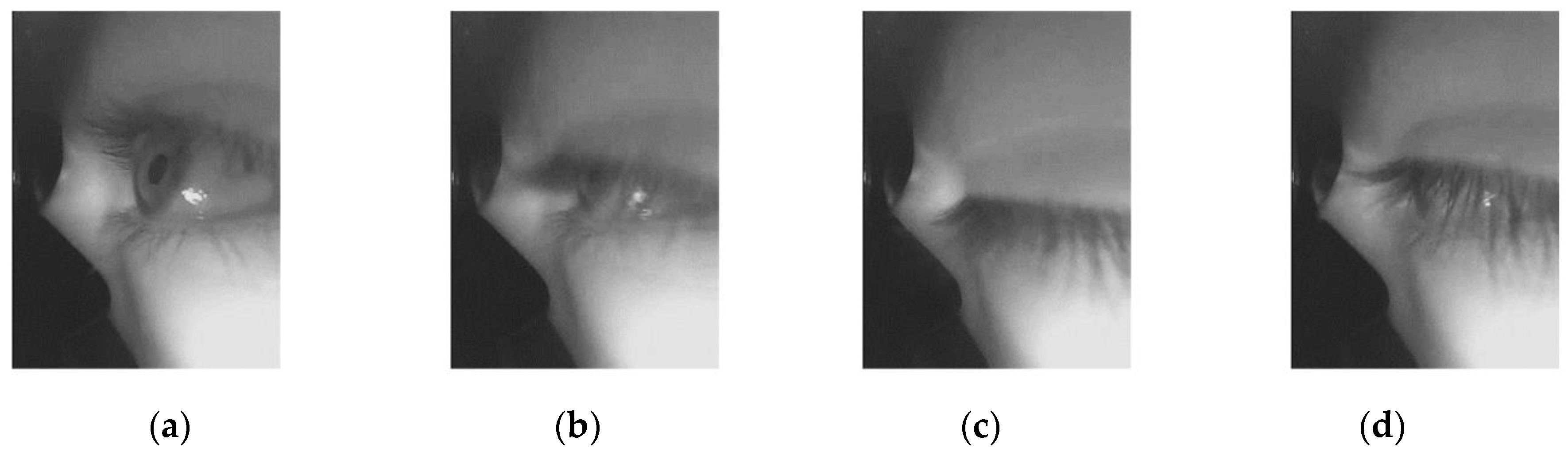
Figure A1.
Eyeblink detection application in action: (a) when the eye is open; (b) during the closing phase; (c) during the pause phase; (d) during the reopening phase.
Figure A1.
Eyeblink detection application in action: (a) when the eye is open; (b) during the closing phase; (c) during the pause phase; (d) during the reopening phase.
References
- Sahayadhas, A.; Sundaraj, K.; Murugappan, M. Detecting driver drowsiness based on sensors: A review. Sensors 2012, 12, 16937–16953. [Google Scholar] [CrossRef] [PubMed]
- Jamil, T.; Mohammed, I.; Awadalla, M.H. Design and Implementation of an Eye Blinking Detector System for Automobile Accident Prevention. In Proceedings of the SoutheastCon, Norfolk, VA, USA, 30 March–3 April 2016. [Google Scholar]
- Victoreia, G.; Yazhini, D.; Parameswari, G.; Gurumoorthi, E.; Vijayabarathy, G. Driver fatigue monitoring system using eye closure. Int. J. Mod. Eng. Res. 2014, 4, 26–31. [Google Scholar]
- Aree, A.M.; Shereen, A.A. Efficient eye blink detection method for disabled-helping domain. IJACSA 2014, 5, 202–206. [Google Scholar]
- Polatsek, P. Eye Blink Detection. In Proceedings of the Informatics and Information Technologies IIT.SRC 2013, Bratislava, Slovakia, 23 April 2013; pp. 1–8. [Google Scholar]
- Fogelton, A.; Benesova, W. Eye blink detection based on motion vectors analysis. Comput. Vis. Image Underst. 2016, 148, 23–33. [Google Scholar] [CrossRef]
- Królak, A.; Strumiłło, P. Eye-blink detection system for human–computer interaction. Univ. Access Inf. Soc. 2012, 11, 409–419. [Google Scholar] [CrossRef]
- Sukno, F.M.; Pavani, S.-K.; Butakoff, C.; Frangi, A.F. Automatic Assessment of Eye Blinking Patterns through Statistical Shape Models. In Computer Vision Systems, Proceedings of the 7th International Conference on Computer Vision Systems, ICVS 2009 Liège, Belgium, 13–15 October 2009, 1st ed.; Fritz, M., Schiele, B., Piater, J.H., Eds.; Springer: Berlin, Germany, 2009; Volume 5815, pp. 33–42. [Google Scholar]
- Ishimaru, S.; Kunze, K.; Kise, K.; Weppner, J.; Dengel, A.; Lukowicz, P.; Bulling, A. (Eds.) In the Blink of an Eye: Combining Head Motion and Eye Blink Frequency for Activity Recognition with Google Glass. In Proceedings of the 5th Augmented Human International Conference, Kobe, Japan, 7–8 March 2014. [Google Scholar]
- Blount, W.P. Studies of the movements of the eyelids of animals: Blinking. Physiol. Soc. 1927, 18, 111–125. [Google Scholar] [CrossRef]
- Bologna, M.; Agostino, R.; Gregori, B.; Belvisi, D.; Ottaviani, D.; Colosimo, C.; Fabbrini, G.; Berardelli, A. Voluntary, spontaneous and reflex blinking in patients with clinically probable progressive supranuclear palsy. Brain 2009, 132, 502–510. [Google Scholar] [CrossRef] [PubMed]
- Kwon, K.-A.; Shipley, R.J.; Edirisinghe, M.; Ezra, D.G.; Rose, G.; Best, S.M.; Cameron, R.E. High-speed camera characterization of voluntary eye blinking kinematics. J. R. Soc. Interface 2013, 10, 20130227. [Google Scholar] [CrossRef] [PubMed]
- Cruz, A.A.V.; Garcia, D.M.; Pinto, C.T.; Cechetti, S.P. Spontaneous eyeblink activity. Ocul. Surf. 2011, 9, 29–41. [Google Scholar] [CrossRef]
- Bentivoglio, A.R.; Bressman, S.B.; Cassetta, E.; Carretta, D.; Tonali, P.; Albanese, A. Analysis of blink rate patterns in normal subjects. Mov. Disord. Off. J. Mov. Disord. Soc. 1997, 12, 1028–1034. [Google Scholar] [CrossRef] [PubMed]
- Stern, J.A.; Walrath, L.C.; Goldstein, R. The endogenous eyeblink. Psychophysiology 1984, 21, 22–33. [Google Scholar] [CrossRef] [PubMed]
- Caffier, P.P.; Erdmann, U.; Ullsperger, P. Experimental evaluation of eye-blink parameters as a drowsiness measure. Eur. J. Appl. Physiol. 2003, 89, 319–325. [Google Scholar] [CrossRef] [PubMed]
- Bacher, L.F.; Allen, K.J. Sensitivity of the rate of spontaneous eye blinking to type of stimuli in young infants. Dev. Psychobiol. 2009, 51, 186–197. [Google Scholar] [CrossRef] [PubMed]
- Zametkin, A.J.; Stevens, J.R.; Pittman, R. Ontogeny of spontaneous blinking and of habituation of the blink reflex. Ann. Neurol. 1979, 5, 453–457. [Google Scholar] [CrossRef] [PubMed]
- Zaman, M.L.; Doughty, M.J.; Button, N.F. The exposed ocular surface and its relationship to spontaneous eyeblink rate in elderly caucasians. Exp. Eye Res. 1998, 67, 681–686. [Google Scholar] [CrossRef] [PubMed]
- Sun, W.S.; Baker, R.S.; Chuke, J.C.; Rouholiman, B.R.; Hasan, S.A.; Gaza, W.; Stava, M.W.; Porter, J.D. Age-related changes in human blinks. Passive and active changes in eyelid kinematics. Investig. Ophthamol. Vis. Sci. 1997, 38, 92–99. [Google Scholar]
- Chambayil, B.; Singla, R.; Jha, R. (Eds.) EEG Eye Blink Classification Using Neural Network. In Proceedings of the World Congress on Engineering, London, UK, 30 June–2 July 2010. [Google Scholar]
- Supek, S.; Sušac, A.; Tiganj, Z.; Mboup, M.; Pouzat, C.; Belkoura, L. (Eds.) An Algebraic Method for Eye Blink Artifacts Detection in Single Channel EEG Recordings. In Proceedings of the 17th International Conference on Biomagnetism Advances in Biomagnetism—Biomag2010, Dubrovnik, Croatia, 28 March–1 April 2010; Springer: Berlin/Heidelberg, Germany, 2010. [Google Scholar]
- Nakanishi, M.; Mitsukura, Y.; Wang, Y.; Wang, Y.-T.; Jung, T.-P. (Eds.) Online Voluntary Eye Blink Detection using Electrooculogram. In Proceedings of the 2012 International Symposium on Nonlinear Theory and its Applications, Palma de Majorca, Spain, 23–26 October 2012. [Google Scholar]
- Hema, C.R.; Paulraj, M.P.; Ramkumar, S. Classification of eye movements using electrooculography and neural networks. Int. J. Recent Trends Hum. Comput. Interact. 2014, 5, 51–63. [Google Scholar]
- Al-gawwam, S. Robust eye blink detection based on eye landmarks and Savitzky–Golay filtering. Information 2018, 9, 93. [Google Scholar] [CrossRef]
- Ivleva, I. Redirected Walking in Virtual Reality During Eye Blink. Bechelor’s Thesis, University of Bremen Faculty of Mathematics and Computer Science, Bremen, Germany, 2016. [Google Scholar]
- Fuhl, W.; Santini, T.; Kasneci, E. Fast and Robust Eyelid Outline and Aperture Detection in Real-World Scenarios. In Proceedings of the IEEE Winter Conference on Applications of Computer Vision (WACV), Santa Rosa, CA, USA, 24–31 March 2017; pp. 1089–1097. [Google Scholar]
- Appel, T.; Santini, T.; Kasneci, E. Brightness and Motion-Based Blink Detection for Head-Mounted Eye Trackers. In Proceedings of the ACM International Joint Conference on Pervasive and Ubiquitous Computing, Heidelberg, Germany, 12–16 September 2016; pp. 1726–1735. [Google Scholar]
- Ho, T.K. Random Decision Forests. In Proceedings of the 3rd International Conference on Document Analysis and Recognition, Montreal, QC, Canada, 14–16 August 1995; IEEE Computer Society Press: Washington, DC, USA, 1995; pp. 278–282. [Google Scholar]
- OmniVision. OV4689 4MP Product Brief; OmniVision: Santa Clara, CA, USA, 2018. [Google Scholar]
- Farnebäck, G. Two-Frame Motion Estimation Based on Polynomial Expansion. In Proceedings of the 13th Scandinavian Conference, SCIA 2003, Halmstad, Sweden, 29 June–2 July 2003; Bigun, J., Gustavsson, T., Eds.; Springer: Berlin/Heidelberg, Germany, 2003; Volume 2749, pp. 363–370. [Google Scholar]
- Vishay Intertechnology. High Speed Infrared Emitting Diode, 850 nm, GaAlAs Double Hetero; Vishay Intertechnology Inc.: Malvern, PA, USA, 2011. [Google Scholar]
- Kasinski, A.; Schmidt, A. The architecture and performance of the face and eyes detection system based on the HAAR cascade classifiers. Pattern Anal. Appl. 2010, 13, 197–211. [Google Scholar] [CrossRef]
- Ahmadi, A. Cascade Trainer GUI. 2016. Available online: http://amin-ahmadi.com/cascade-trainer-gui/ (accessed on 5 July 2018).
- Alsaeedi, N. Eye Blink Detection. 26 January 2019. Available online: https://data.mendeley.com/datasets/9yzdnng594/1 (accessed on 15 February 2019).
- Fawcett, T. An introduction to ROC analysis. Pattern Recognit. Lett. 2006, 27, 861–874. [Google Scholar] [CrossRef]
Figure 1.
Eyeblink phases: (a) An open eye; (b) Closing phase; (c) Pause phase; (d) Reopening phase.
Figure 1.
Eyeblink phases: (a) An open eye; (b) Closing phase; (c) Pause phase; (d) Reopening phase.
Figure 2.
The proportion of each phase with respect to a single blink event, for both spontaneous and voluntary eyeblinks. The calculated values are based on a dataset for healthy controls collected during a study conducted by [
11].
Figure 2.
The proportion of each phase with respect to a single blink event, for both spontaneous and voluntary eyeblinks. The calculated values are based on a dataset for healthy controls collected during a study conducted by [
11].
Figure 3.
The modification on the monitoring camera: (a) Infrared spectrum image for lens mount M8 and IR-LEDs for internal illumination in action; (b) Adding of the custom lens with no IR-cut filter, infrared LEDs for eye illumination and custom 3D printed camera holder; (c) Installing the camera inside the VR-headset (HTC-Vive); and (d) Image sample captured by the camera inside the VR headset.
Figure 4.
Schematic diagram of the illumination circuit.
Figure 4.
Schematic diagram of the illumination circuit.
Figure 5.
The captured frame: (a) Captured frame before the crop, with frame resolution 240 × 320 pixels; (b) Captured frame after the crop, with frame resolution 170 × 320 pixels.
Figure 5.
The captured frame: (a) Captured frame before the crop, with frame resolution 240 × 320 pixels; (b) Captured frame after the crop, with frame resolution 170 × 320 pixels.
Figure 6.
Image coordinates and motion vector calculation: (a) Image 2D coordinates, with the origin being located at the top left corner, the x-axis is pointing to the right and the y-axis is pointing downwards. The sign of the magnitude of the vector component (x and y values) indicates the direction of motion; (b) Frame segment and calculating the motion vector for a single pixel.
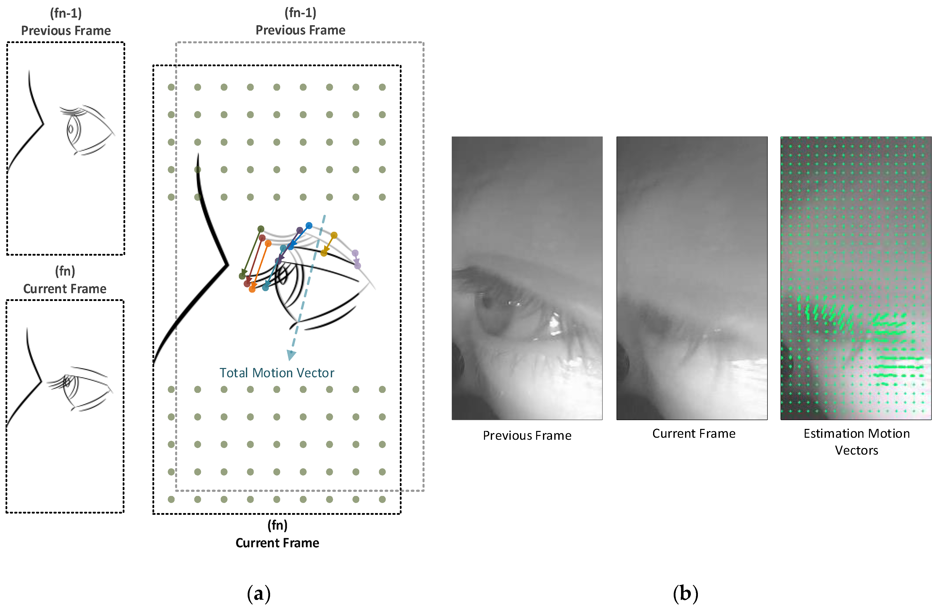
Figure 7.
Illustration of an approximate estimation of a motion vector between two successive frames: (a) Two successively captured frames and how the motion vectors are estimated based on using the previous and current captured frames (fn−1, fn, respectively), and how the sum of vectors represents the motion vector; (b) Real-case scenario, two captured frames and visualisation of the estimation motion vectors by the proposed algorithm.
Figure 8.
Sample images used to train the Haar cascade classifier (HCC): (a) Example of positive samples; (b) Example of negative samples.
Figure 8.
Sample images used to train the Haar cascade classifier (HCC): (a) Example of positive samples; (b) Example of negative samples.
Figure 9.
The finite state machine for open eye template image automatic selection.
Figure 9.
The finite state machine for open eye template image automatic selection.
Figure 10.
The structure for our eyeblink detection algorithm.
Figure 10.
The structure for our eyeblink detection algorithm.
Figure 11.
Finite state machine for identifying eyeblinks and tracking the eye state.
Figure 11.
Finite state machine for identifying eyeblinks and tracking the eye state.
Figure 12.
Eyeblink decision making logic diagram.
Figure 12.
Eyeblink decision making logic diagram.
Table 1.
Durations of three kinematic variables for two types of blinking (voluntary and spontaneous) for healthy subjects in milliseconds [
11].
Table 1.
Durations of three kinematic variables for two types of blinking (voluntary and spontaneous) for healthy subjects in milliseconds [
11].
| Kinematic Variable | Voluntary Blinking | Spontaneous Blinking |
|---|
| Closing duration | 70.8 ± 4.3 | 71.5 ± 4.7 |
| Pause duration | 44.2 ± 9.6 | 13.7 ± 3.3 |
| Reopening duration | 168.5 ± 15.9 | 171.5 ± 13.8 |
Table 2.
Some of the blink kinematic variables: duration of each phase for voluntary and spontaneous blinks. The columns represent the percentage of each phase duration of the whole blink duration, which was roughly calculated for a better understanding of the different durations. The total blink duration was estimated by the summation of that of each phase (closing, pause and opening).
| Kinematic Variable | Voluntary Blink | Percentage | Spontaneous Blink | Percentage |
|---|
| Closing duration | 70.8 ± 4.3 | ~25% | 71.5 ± 4.7 | ~27.9% |
| Pause duration | 44.2 ± 9.6 | ~15.6% | 13.7 ± 3.3 | ~5.3% |
| Reopening duration | 168.5 ± 15.9 | ~59.4% | 171.5 ± 13.8 | ~66.8% |
| Total blink duration | ~283.5 ± 15.9 | --- | ~256.7 ± 13.8 | --- |
Table 3.
Summarised technical specifications of the IR-LED.
Table 3.
Summarised technical specifications of the IR-LED.
| Component | Iө (mW/sr) | Φ (deg) | λp (nm) | tr (ns) |
|---|
| TSHG6400 | 70 | ±22 | 850 | 20 |
Table 4.
Frames count in the tested video samples and the eye localisation method hit rate.
Table 4.
Frames count in the tested video samples and the eye localisation method hit rate.
| Sample File Name | Total Frame Count | Localised ROI Frame Count | Hit Rate |
|---|
| S1 | 31,071 | 31,071 | 1 |
| S2 | 32,230 | 32,230 | 1 |
| S3 | 41,388 | 40,972 | 0.989948777 |
| S4 | 8720 | 8719 | 0.999885321 |
| S5 | 34,355 | 34,354 | 0.999970892 |
| S6 | 20,460 | 20,459 | 0.999951124 |
| S7 | 32,074 | 32,055 | 0.99940762 |
| S8 | 11,278 | 11,277 | 0.999911332 |
| S9 | 57,556 | 57,556 | 1 |
| | | Mean | 0.998786118 |
| | | SD | 0.003129442 |
Table 5.
Frame count, the total number of actual eyeblinks in each sample and duration (in minute).
Table 5.
Frame count, the total number of actual eyeblinks in each sample and duration (in minute).
| Sample File | Frame Count in the File | Count of Real Eyeblinks | Duration of the Video Sample |
|---|
| S1 | 31,071 | 21 | 4:18 |
| S2 | 32,230 | 93 | 5:22 |
| S3 | 41,388 | 61 | 6:00 |
| S4 | 8720 | 19 | 1:12 |
| S5 | 34,355 | 51 | 4:46 |
| S6 | 20,460 | 64 | 2:50 |
| S7 | 32,074 | 14 | 4:27 |
| S8 | 11,278 | 8 | 1:33 |
| S9 | 57,557 | 235 | 9:35 |
| S10 | 41,684 | 169 | 6:56 |
| S11 | 36,345 | 105 | 6:03 |
| S12 | 43,289 | 193 | 8:09 |
Table 6.
The performance evaluation of the proposed method.
Table 6.
The performance evaluation of the proposed method.
| GT | TP | FN | FP | DB | Precision | Recall | Accuracy | FDR |
|---|
| 21 | 19 | 2 | 2 | 23 | 0.905 | 0.905 | 0.826 | 0.095 |
| 93 | 82 | 11 | 8 | 90 | 0.911 | 0.882 | 0.812 | 0.089 |
| 61 | 56 | 5 | 5 | 61 | 0.918 | 0.918 | 0.848 | 0.082 |
| 19 | 14 | 5 | 1 | 15 | 0.933 | 0.737 | 0.700 | 0.067 |
| 51 | 45 | 6 | 3 | 48 | 0.938 | 0.882 | 0.833 | 0.063 |
| 64 | 58 | 6 | 4 | 62 | 0.935 | 0.906 | 0.853 | 0.065 |
| 14 | 12 | 2 | 4 | 16 | 0.750 | 0.857 | 0.667 | 0.250 |
| 8 | 8 | 0 | 0 | 8 | 1.000 | 1.000 | 1.000 | 0.000 |
| 235 | 210 | 22 | 32 | 232 | 0.957 | 0.948 | 0.910 | 0.043 |
| 169 | 160 | 9 | 5 | 165 | 0.970 | 0.947 | 0.920 | 0.030 |
| 105 | 99 | 6 | 6 | 105 | 0.943 | 0.943 | 0.892 | 0.057 |
| 193 | 186 | 7 | 10 | 196 | 0.949 | 0.964 | 0.916 | 0.051 |
| Mean: | | | | 0.918 | 0.904 | 0.839 | 0.082 |
| Standard deviation: | | | 0.060 | 0.063 | 0.088 | 0.060 |
© 2019 by the authors. Licensee MDPI, Basel, Switzerland. This article is an open access article distributed under the terms and conditions of the Creative Commons Attribution (CC BY) license (http://creativecommons.org/licenses/by/4.0/).


