Article

Corrosion Monitoring of Reinforced Steel Embedded in Cement Mortar under Wet-And-Dry Cycles by Electrochemical Impedance Spectroscopy

1
University Core Research Center for Disaster-free and Safe Ocean City Construction, Dong-A University, Busan 49315, Korea
2
Department of Architectural Engineering, Dong-A University, Busan 49315, Korea
*
Authors to whom correspondence should be addressed.
Sensors 2020, 20(1), 199; https://doi.org/10.3390/s20010199
Submission received: 12 November 2019 / Revised: 18 December 2019 / Accepted: 28 December 2019 / Published: 30 December 2019
(This article belongs to the Special Issue Advanced Electrochemical Sensors and Environmental Monitoring)

Abstract

:
The primary objective of the present work is to measure the corrosion rate of reinforcing steel embedded in concrete structures in a simulated marine environment of high chloride concentration. The selection of a single frequency that corresponds to the solution resistance and single frequency that corresponds to the charge transfer resistance were performed and measurements were carried out in a relatively faster time. A total of seven cement mortar specimens were prepared. The effect of varying cover thickness (5–50 mm) and rebar distance (10–80 mm) on the electrical resistance of the concrete and corrosion rate of the steel was examined. To simulate the corrosion of reinforced concrete in a marine environment, cement mortars were exposed to 25 wet–dry cycles that involve an immersion for 8 h in 3 wt.% NaCl solution and drying time of 16 h under room temperature. Alternative current (AC) impedance measurements were carried out within a frequency range from 100 kHz to 1 mHz. Results show that the formation of rust layers on rebars has caused a significant decrease in the maximum phase shift to θ = −30°. An accelerated corrosion rate of the rebars was observed during drying stage.

1. Introduction

The deterioration of civil infrastructures worldwide is mainly induced by steel bar corrosion in concrete [1]. Reinforced concrete structures that have been degraded by environment-induced corrosion are considered hazardous and unstable that could lead to safety problems and unwanted incidents [2]. The occurrence of corrosion in reinforced structures is extremely high in the marine atmospheric environment. Several factors including high-temperature, relatively high humidity and high NaCl concentration contribute to the corrosion of reinforced structures in the marine environment [3,4,5]. The tide ebbing and flooding expose the reinforced structure via soaking in seawater, seawater film covering the structure during wet state and dry state. Moreover, the repetitive alternating wet–dry exposure at high-frequency in tidal zones will lead to an accelerated corrosion of the reinforced structures [6]. Therefore, it is essential to monitor and understand the corrosion state of the reinforced concrete for structure maintenance.
Electrochemical methods are commonly applied to assess and monitor the corrosion of reinforced concrete and cementitious materials [7]. Several corrosion monitoring methods include polarization curve, half-cell potential, multi-electrode array, electrical resistivity, electrochemical noise, and polarization resistance. These technologies are rapid, inexpensive, highly reliable, and cause less structural damage during application [8]. The measurement of the corrosion potential determines the severity of the corrosion condition of the reinforced concrete. Corrosion potential is affected by several structural (stress, roughness, groove, and shape) and environmental (ventilation, temperature, moisture content, and salinity) factors. Most of the methods can only be applied on a laboratory scale that would imply an inaccurate determination of the on-site information on rebar corrosion such as imprecise assessment of corrosion rates [9]. In theoretical and experimental terms, a significant correlation has been established between the polarization resistance and corrosion current density. The polarization resistance has been determined to be useful in assessing corrosion rates and can measured in an alternative current (AC) or DC mode. The monitoring of AC impedance involves the analysis of polarization resistance via extrapolation of the impedance value to frequency f→0 [10].
The alternative current (AC) method, otherwise known as electrochemical impedance spectroscopy (EIS), assesses numerous electrochemical systems based on the characteristics of electrolytic activities [8]. The properties of resistance (or impedance) and frequency assist in the determination of the corrosion state of reinforced concrete. The AC method is applicable to sites that are difficult to analyze by direct current signal. It is known to be useful in understanding both corrosion rate and various electrochemical phenomena. The charge transfer resistance is also determined from the impedance at a low frequency range. One of the advantages of the AC method is the accuracy in the identification for each reaction phenomena occurring at the metal/solution interface based on the frequency range [11]. The AC method has the ability to evaluate the corrosion morphology and state of the rebar. Moreover, it allows the continuous monitoring of the reinforced concrete in its passive or active state [8]. The components of the solution resistance can be separated at high frequency region, which would make the correction on the dynamic voltage (IR) drop possible. Therefore, analysis of the corrosion mechanism is performed and identification of the cause of corrosion (concentration, diffusion, and activation) based on frequency and speed can be carried out. It is essential to accurately measure the corrosion rate of rebars in concrete that is continuously exposed to the wet and dry process, which increases the electrolyte resistance. The occurrence of corrosion on metal surfaces is categorized as a non-stationary system. With passing time, oxides on metal surfaces form that cause changes in corrosion potential and corrosion rate. A conventional EIS measures the corrosion rate on a continuously changing surface by setting the corrosion potential or fixed voltage at the start of the experiment. Dynamic EIS utilizes a separate reference electrode to measure the corrosion rate of oxides on the metal surface using different potential, which would focus on the change in corrosion behavior over time [12]. The group of Tsuru and Nishikata has used two-electrode cell type to monitor corrosion rates using the same component and size material for both working electrode and reference/counter electrode. The rates of non-stationary corrosion system are measured under various corrosion environments including atmospheric condition [10,13,14,15,16,17,18].
The purpose of this study is to evaluate the capacity of EIS for fast and accurate measurement of the corrosion in reinforced concrete structures that have been repeatedly exposed to seawater immersion and drying. The factors affecting the non-uniformity of the current distribution and IR drop on the surface of the reinforced bar (rebar) were evaluated. To simulate the marine environment, mortar specimens are embedded with rebars and exposed to repeated cycles of immersion in 3 wt.% NaCl solution and drying at room temperature. The corrosion rate of the rebars was monitored using two selected frequencies for high-speed measurement.

2. Materials and Methods

2.1. EIS Model of Reinforced Steel in Concrete

The frequency domain is applied in an EIS method such that the interface of the rebar embedded in concrete can be represented as an equivalent electric circuit comprised of resistance, inductance, and capacitance [8]. In this study, the EIS equivalent circuit model consists of solution resistance (Rs), charge transfer resistance (Rc), constant phase element (CPE), and Warburg impedance (W; Figure 1). Rs represents the electrical resistance generated along the electrolyte solution found within the cement void. Rc refers to the resistance of the charge transfer involved in the corrosion mechanism. The electric double layer capacity (Cdl) refers to the double layer capacity at the interface between cement mortar and rebar while W refers to the diffusion caused by corrosion.
The total impedance (Z) are represented by Equation (1):
Z = R S + R c 1 + j ω C dl R c ,
where j is a complex number that is determined by the frequency response analyzer and ω is the frequency. At high frequencies (ω→∞), the capacitor impedance is 1/ω Cdl→0 that would result in the measurement of Rs. Meanwhile, Rs + Rc is measured at low frequency (ω→0). In other words, Rp, a polarization resistance, is the difference between the high and low frequency impedance as shown in Equation (2).
R P = Z low_frequency Z high_frequency .
The Stern–Geary equation (Equation (3)) was used to obtain the corrosion current density (icorr) from the polarization resistance [19]
i corr = k R P ,
where k is a proportional constant and computed using Equation (4):
k = b a b c 2.303 ( b a + b c ) ,
where ba and bc are the Tafel gradients of the positive and negative polarization curves, respectively. In the current study, the value of k = 0.025 V/dec has been applied [20].

2.2. Preparation of Specimens

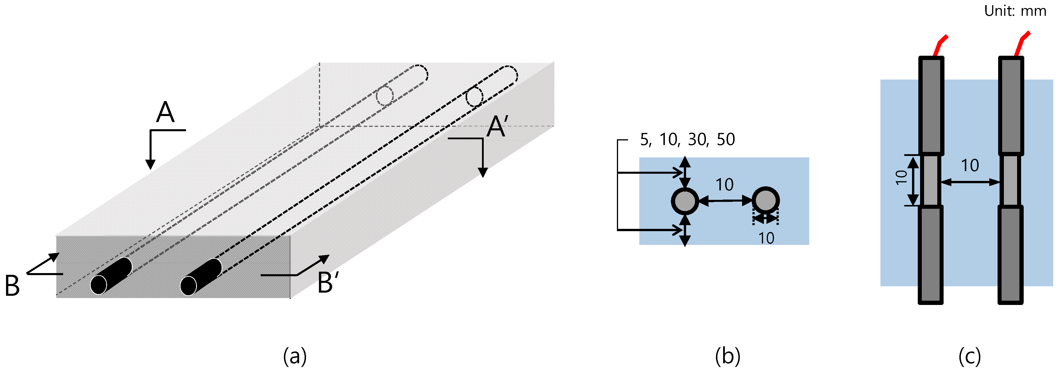
The configuration of the concrete specimens is shown in Figure 2. Two rebars of 10 mm in diameter and 100 mm in length were embedded at the center of the cement mortar sample. Each rebar was insulated with a 45-mm heat-shrink tube and B-coating agent on both ends and 10 mm of length was exposed to allow direct attachment to the mortar. The area exposed to concrete for each rebar was fixed at 6 cm2. The cement mortar specimens were prepared using Portland cement and ISO standard yarn with a water-cement ratio of 0.6 and cement-sand ratio of 0.5. As shown in Table 1, a total of seven specimens were fabricated under varying cover thickness (5–50 mm) and rebar spacing (10–80 mm). The rebars were fixed by drilling the mold before placement of the concrete.

2.3. Wet–Dry Cycle

A wet–dry cycle refers to the process of immersing the specimen in 3 wt.% NaCl solution for 8 h and dried under room temperature for 16 h. A total of 25 wet–dry cycles was performed in this study. The NaCl solution was prepared using analytical grade NaCl (99.0% purity, Daejung, South Korea) and distilled water.
AC impedance measurements were performed to determine the electrical resistance of concrete and steel corrosion rate using the multichannel electrochemical workstation (Won-A tec, ZIVE MP2) with an amplitude of ±10 mV. The impedances were measured using the equipment operated at low and high frequency of 10 mHz and 10 kHz, respectively. At the end of the wet–dry test, the impedance of selected cycles (2, 4, 18, and 26 cycles) with an amplitude of ±10 mV was measured under frequency range of 1 mHz–100 kHz. The Rs and Rc were calculated by regression analysis based on the EIS model [21]. All AC impedance measurements were done with a two-electrode system, the same components and same exposed surface to electrolyte.

3. Results

3.1. Corrosion Behavior of Wet–Dry Cycle

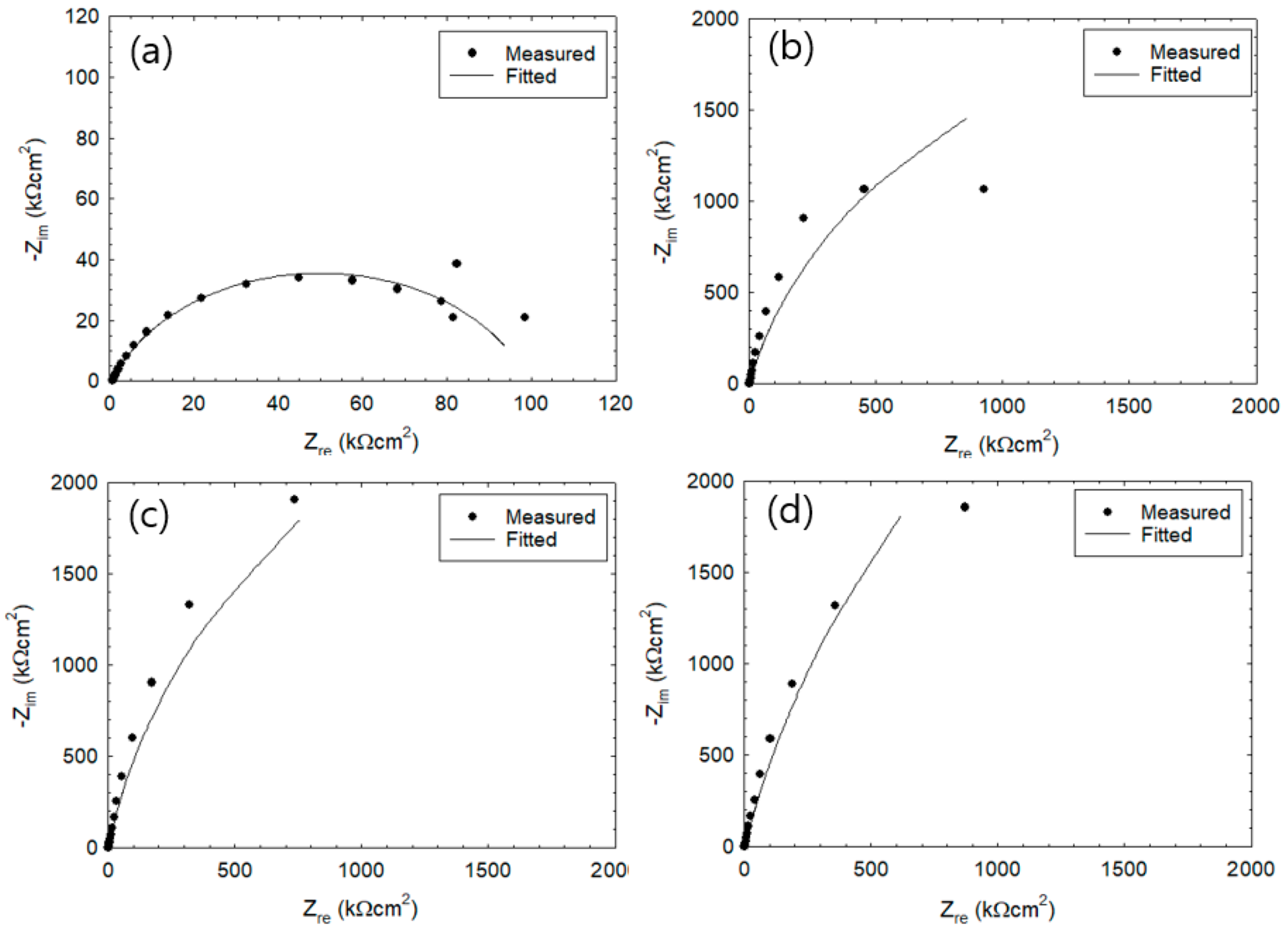
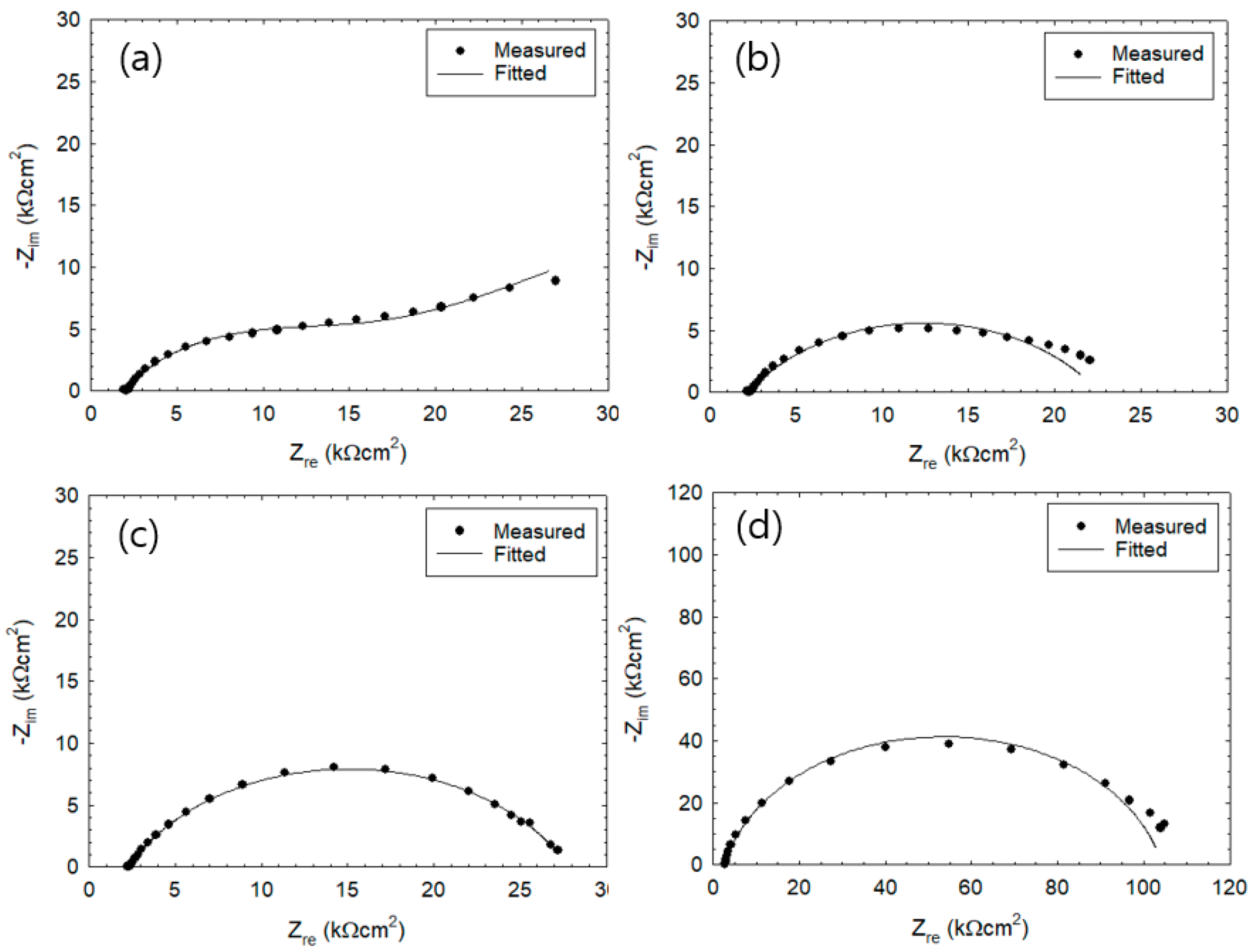
In Figure 3 and Figure 4, the Nyquist plots (or Cole–Cole plots) show the impedance measured after 2nd and 26th wet–dry cycle. The lines represent the fitting results. In the equivalent circuit depicted in Figure 1, Rc represents the charge transfer resistance, Rs the solution resistance, CPE the constant phase element, and W the Warburg impedance of diffusion. Table 2 summarizes values of parameters used for the fitting. CPE parameters are represented by T and α1. When α1 = 1, CPE would become capacitive, being equal to the electric double layer capacitance Cdl (µF/cm2). Impedance ZCPE of CPE is represented by
Z CPE = 1 [ T ( j ω ) α 1 ] ,
where j refer to the complex and ω is the angular frequency. That is, impedance, consisting of a parallel connection of Rc and CPE, would yield a semi-circle trace when α1 = 1 and, as the α1 value becomes smaller, the semi-circle would become increasingly distorted. Warburg impedance W is composed of a resistance component WR, a capacitance component WT, and a calibration factor α2, Provided that the mode of diffusion was finite, impedance ZW of W is represented by
Z W = WRtanh [ ( jWT ω ) α 2 ] ( jWT ω ) α 2 ,
when α2 = 0.5, impedance of diffusion yields a straight line with 45° over the Nyquist plot and, with further decrease of α2, the slope of the straight line becomes smaller. For now, exact physical significances of the parameters, α1 and α2, are not clear but these parameters certainly refer to some aspects of electrode reaction heterogeneity. The optimum EIS curve derived from EIS equivalent circuit (Figure 1) is represented by a line and was fitted with the experimental Nyquist plot [7]. The experimental data were fitted with the theoretical curves generated by Equations (5) and (6). Results show that experimental data during 26th cycle are in good agreement with the fitted curves. Meanwhile, experimental results from 2nd cycle do not agree well with the fitted curves. The Nyquist plot at Figure 3a showed one large semi-circle while Figure 3b–d showed similar behavior where the initial state showed half of a large semicircle. After the 25th cycle of wet–dry exposure test (Figure 4a–d), the overall size of the semicircle has significantly reduced in size. Figure 4a shows a semi-circle with gentle slope that increases toward the right. The values of Zre were observed to decrease as the monitoring progressed from 2nd cycle (Figure 3) to 26th cycle (Figure 4).
The present work used test specimens that have been cured for 21 days and demolded. The Rs values during 1st cycle showed higher value within the range of 1–2 kΩcm2, which is due to Ca(OH)2 produced by mortar hydration. However, the penetration of chloride ions into the mortar would result in rapid decreases in the resistance of the solution.
Table 2 shows the electrochemical impedance parameters such as Rs, Cdl, Rc, and W that were obtained by fitting the model. The values of Rc were found within the range from 119 to 15,000 kΩcm2 at 2nd cycle and were observed to decrease significantly at the 26th cycle (Rc = 16–101 kΩcm2). The specimen with 5 mm thickness during the 26th cycle was observed to have the Rc values reduced to 16.9 kΩcm2 where the Nyquist plot showed a distorted semicircle shape within the low frequency range. The Rs values were determined to be within the range of 0.7–1.0 kΩcm2 and 2.0–2.6 kΩcm2 after the 1st and 26th cycle, respectively.
The α1 values of the CPE in the 2nd cycle under immersion state were determined to be in the range of 0.79–0.91, which is close to 1. On the other hand, the T value in the initial state can be considered as Cdl. With increasing cycle, the T value was observed to increase while α1 value was observed to decrease. The trend became more pronounced as the mortar thickness becomes thinner. Figure 3 and Figure 4b–d show the rebar surface at passive stage and low corrosion rate, which is controlled by the charge transfer step. In Figure 4a, the corrosion rate is controlled by the mass transfer step with Warbug diffusion impedance.

3.2. Measurement of Rp Via the Two-Frequency Method

The two-frequency impedance method is applied to quickly measure the corrosion rate of rebar embedded in concrete exposed to wet–dry cycles. In general, measurement of the corrosion rate of metal via AC impedance method would utilize a sample size of 5 point/decade within a high frequency region that corresponds to the solution resistance (Rs) and low frequency region that corresponds to the charge transfer resistance (Rc). The measurement at low frequency region takes a longer time to complete, which renders it difficult to quickly measure changes in corrosion rate caused by varying wettability of the reinforced concrete.
A comparative study was conducted in the wet–dry environment for the selection of the appropriate frequency for Rc and Rs. As shown in Figure 5, bode plots illustrate the absolute value of the impedance measured during the 18th wet–dry cycle. Under wet condition, measurement of impedance started after 2 h of immersion while measurement of the AC impedance under dry conditions started after 12 h. In the low frequency region, high Rc values were obtained under dry condition when compared to the immersed condition. The difference in maximum phase shift is between 1 and 0.1 Hz, which is equivalent to the EIS circuit. The generated current flows on Rs + Rc at frequency range of 0.1–1.0 Hz with voltage of ±10 mV. Therefore, the frequency lower than 0.1–1.0 Hz was selected that would correspond to Rc. Table 3 compares the results of the AC impedance measurement using 5 mm mortar thicknesses against EIS fittings. It can be seen that as the number of wet–dry cycles increases, there is also a corresponding increase in the corrosion rate while the error (%) was observed to decrease [14].

3.3. Monitoring of Corrosion Rate

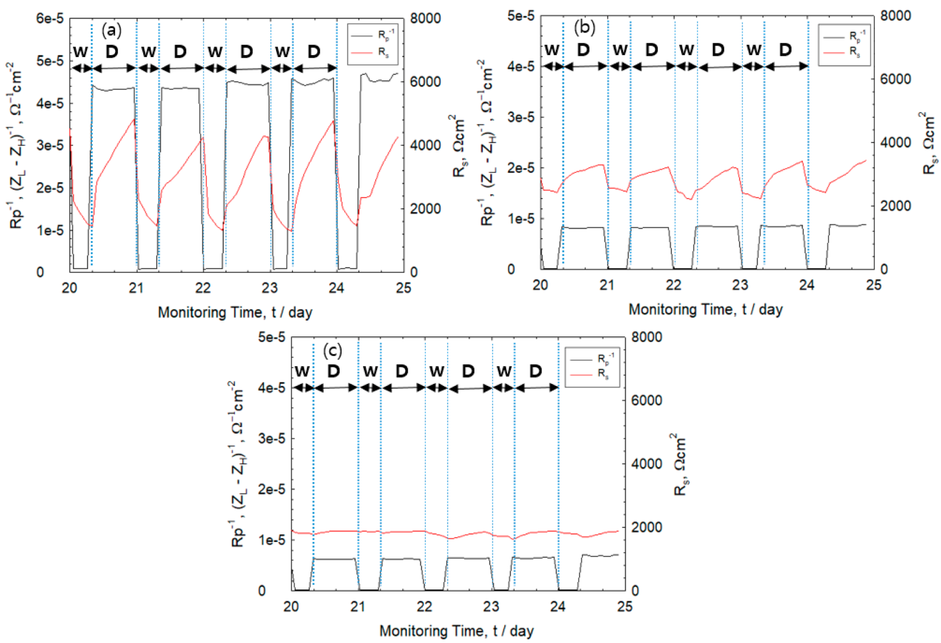
Figure 6 shows the change in the values of Rs and Rp−1 during the period of 20th–25th cycle. The solution resistance of the rebar-mortar interface was measured using 10 kHz in the high frequency region. Meanwhile, the corrosion rate (Rp) was computed from Rp = Rc − Rs. The value of Rc is measured in the low frequency region at 10 mHz. The values of Rp−1 for all specimens were observed to increase rapidly as it changes from the wet to the dry state and the values decreased rapidly from dry to wet state. A cover thickness of 30 mm resulted in relatively constant values of Rs for both the wet and dry state. On the other hand, an increase in Rs values was observed as drying progressed at cover thickness of 5 and 10 mm. Results show the importance of measuring the electrochemical parameters in the dry state in order to accurately measure the corrosion rate of reinforced concrete structures exposed to repeated wet–dry saline environments.
Figure 7 shows the values of corrosion rates and Rs obtained for the 1st–25th cycle for cover thickness of 5, 10, and 30 mm. The Rp−1 is expressed as the reciprocal of the polarization resistance and defined as an index of corrosion rate [16]. It was observed that there was an increase in the corrosion rate for all specimen wherein the highest rate of corrosion was displayed by rebar with 5 mm mortar thickness. The corrosion rate can be classified into four types: passivation region (Rp−1 ≤ 4 × 10⁻⁶ Ω−1cm−2), low/middle (4 × 10⁻⁶ Ω−1cm−2 < Rp−1 ≤ 4 × 10⁻⁵ Ω−1cm−2), high (4 × 10⁻⁵ Ω−1cm−2 < Rp−1 ≤ 4 × 10⁻⁴ Ω−1cm−2), and very high (4 × 10⁻⁴ Ω−1cm−2 < Rp−1 ≤ 4 × 10⁻³ Ω−1cm−2) [22,23]. The corrosion rate of rebar with cover thickness of 5 mm is classified as mid-range type while other specimens are categorized to have low corrosion rates. In Figure 7a–c, the red solid line does not take into account the value of Rs from Rc while the black solid line shows Rp attained by Rs corrected from Rc. At a cover thickness of 5 mm, high corrosion rate implies greater rust formation that would result in high error values.
As seen in Figure 7a, thickness of 5 mm is characterized by relatively high corrosion rates and increasing values of Rs in the dry state. This indicates that the corrosion rate may be miscalculated if Rs is not corrected. Meanwhile, a relatively large mortar thickness of 10 and 30 mm displayed low corrosion rates (Figure 7b,c). In general, DC-based polarization resistance method is widely applied in the accurate measurement of corrosion rate. The method mainly determines the Rc value and has difficulty in measuring Rs values. However, higher corrosion rates and changes in Rs such as exposure to its drying state and formation of rust products at the rebar-mortar interface could lead to imprecise measurements [24,25]. In contrast, the two frequency-based AC method can easily correct the effect of Rs value and accurately measure the corrosion rate.

3.4. Effect of IR Drop on Corrosion Rate

In general, the corrosion rate of reinforced steel in concrete that is repeatedly exposed to wet–dry cycles such as splash zones is greater than consistent exposure to either wet or dry environment. The electrochemical changes in reinforced concrete under repeated wet–dry cycle was evaluated and discussion on the limitations in the field measurement via the EIS method was carried out.
In Figure 8, the bode plot illustrates the impedance phase difference between incoming voltage and output voltage in the 4th and 18th cycle. The EIS impedance was measured continuously in the frequency range of 100 kHz–1 mHz. Results show that 10 kHz is applicable for Rs value. The frequency selected that corresponds to Rs + Rc was at a frequency lower than 1–0.1 Hz [14]. When the maximum phase shift that represents the electric double layer exceeds θ = −45° under any frequency, it is known that the current line distribution measured in the frequency region lower than the arbitrary frequency is uniform [14].
Table 4 illustrates the Rs, T, and Rc values of 4th and 18th cycle. The progress from 4th–18th cycle shows an increase in the values of Rs and T and decrease in Rc values. This is attributed to the penetration of chloride into the mortar that destroys the passivation film on the rebar surface and accelerates rust formation.

3.5. Effect of Corrosion Product on IR Drop

Figure 8 shows the results of the AC impedance measurements on the initial (4th) and last (18th) stage of the wet–dry state of rebars with 5 mm mortar thickness. It was observed that less corrosion products have formed on the rebar surface at the 4th cycle when compared to 18th cycle. Particularly, the rebar surface in the 18th cycle has a high corrosion rate that would result in greater volume of corrosion products formed. The maximum phase shifts were observed to occur from −65 to −35°, which is attributed to the non-uniformity of errors on the IR drop caused by corrosion products.

3.6. Effect of Drying Condition on IR Drop

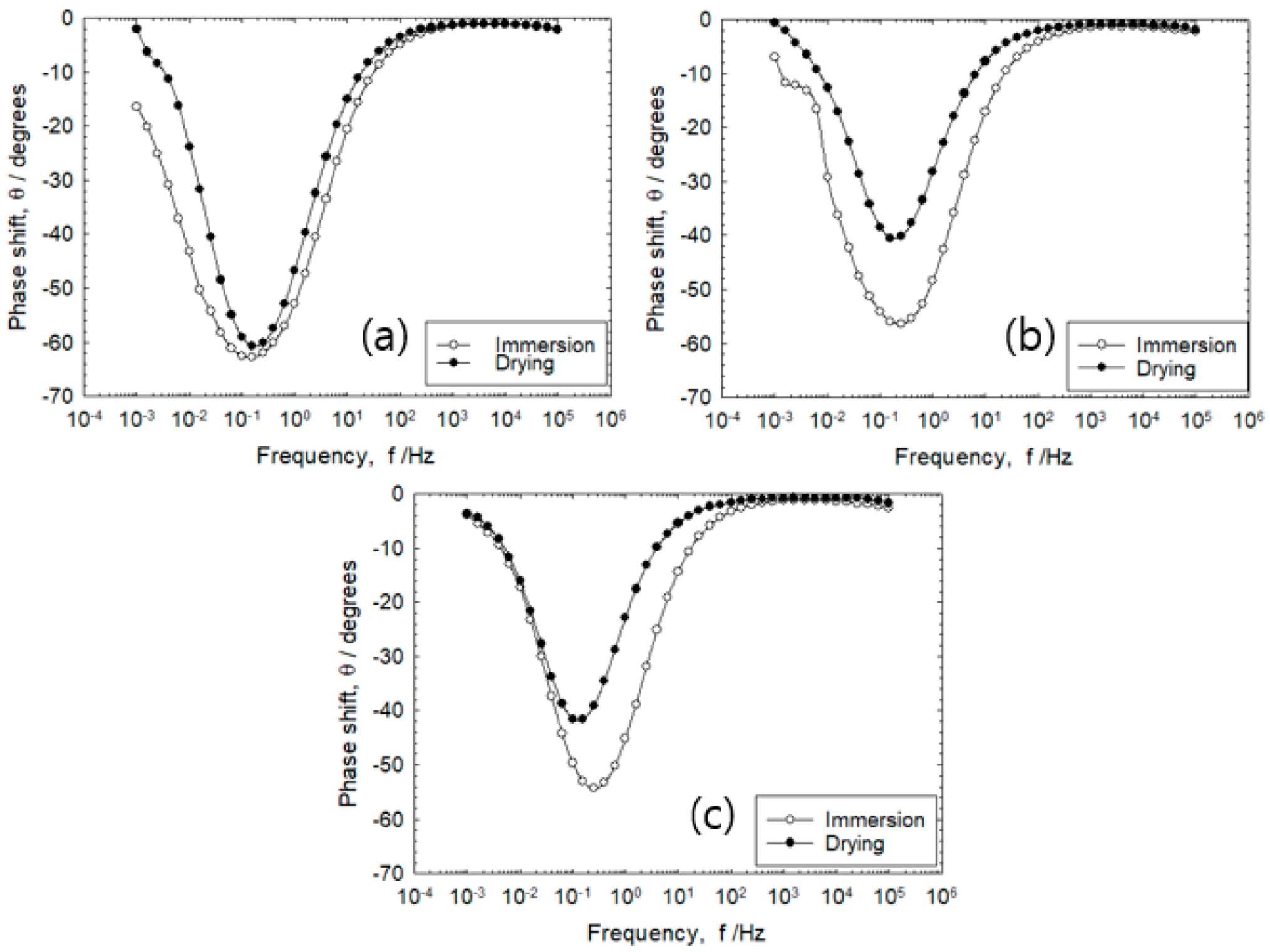
As shown in Figure 8, comparing the maximum phase shift of the initial and last stage, the phase shift was observed to rapidly decrease to −35° at 18th cycle. At mortar thickness of 5 mm, high quantity of corrosion products were generated and the maximum phase shift was observed to decrease to θ = −25° during the drying process.
Figure 9 shows the impedance characteristics measured after 5th cycle of immersion and drying. Regardless of the distance between the two electrodes, the current line distribution remains relatively constant because the maximum phase shift is around θ = −60° during immersion. When the specimen of 30 mm and 80 mm is in a dry state, the maximum phase shift was observed to rise rapidly to θ = −45° or less. In the dry state, the Rs value was observed to increase from 2.3 to 5.8 kΩcm2 as the rebar distance was increased from 10 to 80 mm, respectively. The difference in Rs value was 3.5 kΩcm2. On the other hand, the immersion state achieved Rs values of 1.1 kΩcm2 for 10 mm and 1.7 kΩcm2 for 80 mm with a difference of 0.6 kΩcm2, which was about 5.7 times lower than in the dry state. This was in agreement with the results that Rs sharply increased during the drying process when compared during immersion, which caused the IR drop. Hence, it has been considered to cause inaccuracy in the monitoring of the corrosion rate via the linear polarization resistance measurement method by direct currents [15].

4. Discussion

The good fit of Nyquist plots at 26th cycle implies that Equations (5) and (6) can adequately represent the results due to the presence of thinner electrolyte layer [13]. In the dry state, high Rp−1 values and high Rs values would yield lower polarization resistance and accelerated mass transport rate of dissolved oxygen at the rebar-mortar interface, which would result in higher corrosion rates [10,14,16,17,26]. This implies that the process of the rebar-mortar interface (in its completely dried up state) would cause an increase in the rate of corrosion.
The decrease in Rs values as wet–dry cycle increases from 1st to 25th cycle could be attributed to the dissolution of the passivation film that would result in greater salt infiltration and increase in the mass transport rate of dissolved oxygen within the mortar [27,28]. Meanwhile, a corresponding increase in the Rs values was observed as the number of cycles increased. This implies that the corrosion of rebar proceeded as the wet–dry cycles were repeated, which resulted in an increase in electrical resistance due to precipitation of corrosion products within the pores that exists at the rebar–mortar interface [16]. Although this value is not directly related to the corrosion of rebars, the value can be used as an environment indicator for steel corrosion. The T value increases while α1 value decreases as the wet–dry cycle increases due to the non-uniformity of the rebar surface caused by the adhesion of corrosion products [10]. During the dry cycle, high corrosion rates (Rp−1) were observed due to the formation of oxide layers. Meanwhile, Rs values increased as a result of the removal of bulk solution at the onset of the drying cycle. The increasing Rs value is also attributed to the presence of thinner electrolyte layers during drying [28].
Based on the transmission line circuit behavior proposed by Nishikata et al. (1996), the changes in phase shift from −65° at the 4th cycle to −35° at the 18th cycle implies that there is an increase in rust formation. This would mean corrosion rates are higher at 18th cycle in comparison to the 4th cycle [13].
The constant values of corrosion rate and Rs attained at cover thickness of 30 mm implies that a thicker cover of the mortar requires a longer drying time for the concrete surrounding the rebars. Meanwhile, high corrosion rates were observed for cover thickness of 5 mm followed by 10 mm and 30 mm. Decreasing mortar thickness would imply higher rates of moisture evaporation and salt penetration that would result in higher corrosion rates. The higher corrosion rate in the drying period is caused by the increased reduction rate of dissolved oxygen [26]. In the dry stage, higher rebar distance of 30 and 80 mm causes a rapid rise in phase shift. This signifies that increasing the distance between electrodes would result in uneven current distribution due to drying of the mortar pores between the rebars [17].

5. Conclusions

The present study evaluated the monitoring of reinforced concrete via electrochemical method. The specimens were repeatedly submerged in NaCl solution and air-dried for a total of 25 wet–dry cycles, and the following conclusions were made:
  • During the early stage of wet–dry cycle, the rebar/mortar is represented by a simple equivalent circuit. As the wet–dry cycle progresses, chloride ion penetration would cause the charge transfer resistance to decrease. Meanwhile, the Warbug impedance that represents oxygen diffusion in the mortar was detected in the low frequency range.
  • During the drying stage, both corrosion rate and Rs of the rebars were observed to increase rapidly. The Rs value was observed to become higher under dry condition, which is attributed to thinner electrolyte layers and higher corrosion rate of the rebar. The high corrosion rate indicates formation of oxide layers during the drying cycle.
  • During monitoring of the corrosion rate via AC impedance, accurate measurement of the polarization resistance was ensured by compensating the IR drop based on the dry state of the specimen and quantity of corrosion products found on the rebar surface.
  • The value of the polarization resistance corrected using Rs was different from the polarization resistance without Rs correction, attributed from drying condition, rust layer, distance between electrodes.
  • The percent error (%) of the charge transfer resistance and polarization resistance derived from the fitting of Nyquist plots with the experimental results at 10 mHz/10 kHz was observed to decrease with increasing wet–dry cycles.

Author Contributions

Conceptualization, methodology and investigation—J.-K.K.; Formal analysis J.-K.K.; Writing—original draft—J.-K.K. and C.M.F.; Writing—reviewing and editing—C.M.F.; Supervision—S.-H.K. and J.-J.Y.; Resources—S.-H.K. and J.-J.Y.; Funding Acquisition—J.-J.Y. All authors have read and agreed to the published version of the manuscript.

Funding

This research was funded by the National Research Foundation (Korea) through the Ministry of Education, No. 2016R1A6A1A03012812.

Conflicts of Interest

The authors declare no conflict of interest.

References

  1. Sohail, M.G.; Kahraman, R.; Alnuaimi, N.A.; Gencturk, B.; Alnahhal, W.; Dawood, M.; Belarbi, A. Electrochemical behavior of mild and corrosion resistant concrete reinforcing steels. Constr. Build. Mater. 2020, 232, 117205. [Google Scholar] [CrossRef]
  2. Dong, S.-G.; Lin, C.-J.; Hu, R.-G.; Li, L.-Q.; Du, R.-G. Effective monitoring of corrosion in reinforcing steel in concrete constructions by a multifunctional sensor. Electrochim. Acta 2011, 56, 1881–1888. [Google Scholar] [CrossRef]
  3. Cao, M.; Liu, L.; Yu, Z.; Fan, L.; Li, Y.; Wang, F. Electrochemical corrosion behavior of 2A02 Al alloy under an accelerated simulation marine atmospheric environment. J. Mater. Sci. Technol. 2019, 35, 651–659. [Google Scholar] [CrossRef]
  4. Lu, S.; Wang, Z. Macro-Cell Current Measured by Tower-Type Sensor in Chloride-Contaminated Mortar. IEEE Sens. J. 2011, 11, 1711–1712. [Google Scholar] [CrossRef]
  5. Lu, S.; Ba, H.-J. Corrosion sensor for monitoring the service condition of chloride-contaminated cement mortar. Sensors 2010, 10, 4145–4158. [Google Scholar] [CrossRef] [PubMed]
  6. Mu, X.; Wei, J.; Dong, J.; Ke, W. In Situ Corrosion Monitoring of Mild Steel in a Simulated Tidal Zone without Marine Fouling Attachment by Electrochemical Impedance Spectroscopy. J. Mater. Sci. Technol. 2014, 30, 1043–1050. [Google Scholar] [CrossRef]
  7. Chi, L.; Wang, Z.; Lu, S.; Zhao, D.; Yao, Y. Development of mathematical models for predicting the compressive strength and hydration process using the EIS impedance of cementitious materials. Constr. Build. Mater. 2019, 208, 659–668. [Google Scholar] [CrossRef]
  8. Ribeiro, D.V.; Abrantes, J.C.C. Application of electrochemical impedance spectroscopy (EIS) to monitor the corrosion of reinforced concrete: A new approach. Constr. Build. Mater. 2016, 111, 98–104. [Google Scholar] [CrossRef]
  9. Jeong, J.-A. Consideration on the Risk of Corrosion Assessment in Reinforced Concrete Structure by Corrosion Potential Criterion. Corros. Sci. Technol. 2015, 14, 147–152. [Google Scholar] [CrossRef] [Green Version]
  10. Kim, J.K.; Nishikata, A.; Tsuru, T. Impedance Characteristics of Reinforcing Steel in Mortar and Corrosion Monitoring. Zairyo-to-Kankyo 2002, 51, 57–67. [Google Scholar] [CrossRef]
  11. Nishikata, A.; Zhu, Q.; Tada, E. Long-term monitoring of atmospheric corrosion at weathering steel bridges by an electrochemical impedance method. Corros. Sci. 2014, 87, 80–88. [Google Scholar] [CrossRef]
  12. Ryl, J.; Darowicki, K. Impedance Monitoring of Carbon Steel Cavitation Erosion under the Influence of Corrosive Factors. J. Electrochem. Soc. 2008, 155, P44–P49. [Google Scholar] [CrossRef]
  13. Nishikata, A.; Ichihara, Y.; Tsuru, T. Electrochemical impedance spectroscopy of metals covered with a thin electrolyte layer. Electrochim. Acta 1996, 41, 1057–1062. [Google Scholar] [CrossRef]
  14. Nishikata, A.; Ichihara, Y.; Tsuru, T. An application of electrochemical impedance spectroscopy to atmospheric corrosion study. Corros. Sci. 1995, 37, 897–911. [Google Scholar] [CrossRef]
  15. Haruyama, S.; Tsuru, T. STP727 Electrochemical Corrosion Testing ASTM; ASTM International: West Conshohocken, PA, USA, 1981. [Google Scholar]
  16. Yadav, A.P.; Nishikata, A.; Tsuru, T. Electrochemical impedance study on galvanized steel corrosion under cyclic wet–dry conditions––influence of time of wetness. Corros. Sci. 2004, 46, 169–181. [Google Scholar] [CrossRef]
  17. Yadav, A.P.; Katayama, H.; Noda, K.; Masuda, H.; Nishikata, A.; Tsuru, T. Effect of Fe–Zn alloy layer on the corrosion resistance of galvanized steel in chloride containing environments. Corros. Sci. 2007, 49, 3716–3731. [Google Scholar] [CrossRef]
  18. Xia, D.-H.; Song, S.; Qin, Z.; Hu, W.; Behnamian, Y. Review—Electrochemical Probes and Sensors Designed for Time-Dependent Atmospheric Corrosion Monitoring: Fundamentals, Progress, and Challenges. J. Electrochem. Soc. 2020, 167, 037513. [Google Scholar]
  19. Stern, M.; Geary, A.L. Electrochemical Polarization I. A Theoretical Analysis of the Shape of Polarization Curves. J. Electrochem. Soc. 1957, 104, 56–63. [Google Scholar] [CrossRef]
  20. Kim, J.N.; Jee, N.Y. A Study on the Distribution of Stern-Geary Constant for Calculating the Corrosion Current Density of Steel Reinforcement in Concrete by Means of the Polarization Resistance Method. Korea Soc. IT Serv. 2007, 11, 113–121. [Google Scholar]
  21. Macdonald, D.D. Reflections on the history of electrochemical impedance spectroscopy. Electrochim. Acta 2006, 51, 1376–1388. [Google Scholar] [CrossRef]
  22. BRE. Digest 444 Corrosion of Steel in Concrete: Part 2—Investigation and Assessment Building Research Establishment; BRE: Bracknell, UK, 2000. [Google Scholar]
  23. Joh, S.H.; Lim, Y.C.; Ismail, M.; Lee, H.S. Fundamental Study on Developing Embedded Miini- Sensor for Nondestructive Diagnosis Corrosion of Rebar. J. Korea Inst. Struct. Maint. Insp. 2010, 14, 179–186. [Google Scholar]
  24. Jones, D.A. Principles and Prevention of Corrosion, 2nd ed.; Prentice Hall: Upper Saddle River, NJ, USA, 1996; ISBN 978-0-13-359993-0. [Google Scholar]
  25. Kouřil, M.; Novák, P.; Bojko, M. Limitations of the linear polarization method to determine stainless steel corrosion rate in concrete environment. Cem. Concr. Compos. 2006, 28, 220–225. [Google Scholar] [CrossRef]
  26. Tomashov, N.D. Theory of Corrosion and Protection of Metals: The Science of Corrosion; Macmillan: New York, NY, USA, 1966. [Google Scholar]
  27. Shi, W.; Dong, Z.H.; Kong, D.J.; Guo, X.P. Application of wire beam electrode technique to investigate initiation and propagation of rebar corrosion. Cem. Concr. Res. 2013, 48, 25–33. [Google Scholar] [CrossRef]
  28. Cruz, R.P.V.; Nishikata, A.; Tsuru, T. AC impedance monitoring of pitting corrosion of stainless steel under a wet–dry cyclic condition in chloride-containing environment. Corros. Sci. 1996, 38, 1397–1406. [Google Scholar] [CrossRef]
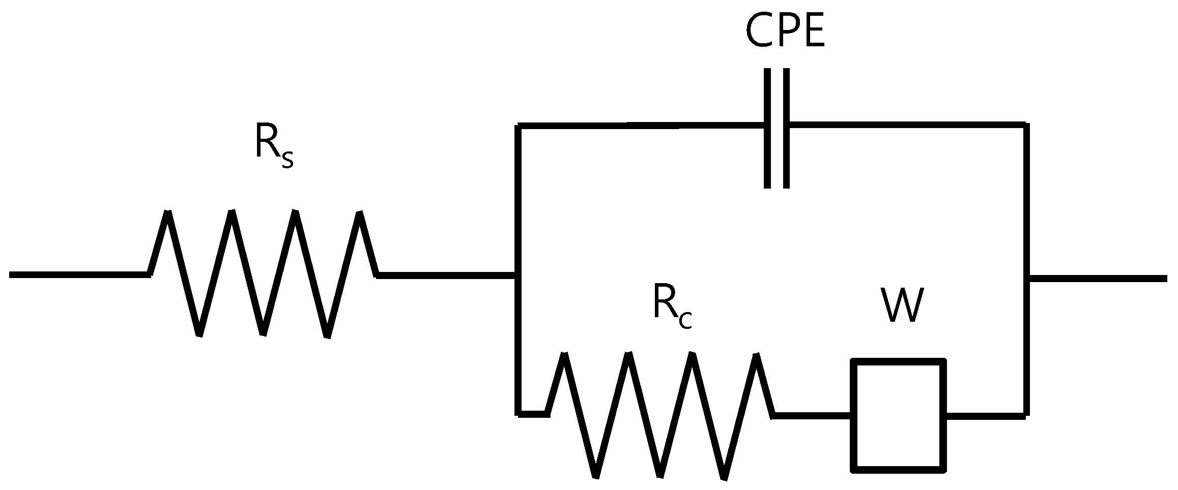
Figure 1. Equivalent electrochemical impedance spectroscopy (EIS) model of a reinforced steel in concrete [10].
Sensors 20 00199 g001
Figure 2. The (a) isometric view, (b) sectional view A–A’, and (c) sectional view B–B’ of the specimen configuration of reinforced steel in a concrete specimen.
Sensors 20 00199 g002
Figure 3. Cole–Cole plot of reinforced steel during the 2nd wet–dry cycle with cover thickness of (a) 5 mm, (b) 10 mm, (c) 30 mm, and (d) 50 mm.
Sensors 20 00199 g003
Figure 4. Cole–Cole plot of reinforced steel during the 26th wet–dry cycle with cover thickness of (a) 5 mm, (b) 10 mm, (c) 30 mm, and (d) 50 mm.
Sensors 20 00199 g004
Figure 5. Bode diagram of reinforced concrete in the 18th cyclic with cover thickness of 5 mm measured under (a) immersed and (b) dry condition.
Sensors 20 00199 g005
Figure 6. Monitoring of polarization resistance (Rp−1) and solution resistance (Rs) measured from 20th to 25th wet (W)–dry (D) cycle with cover thickness of (a) 5 mm, (b) 10 mm, and (c) 30 mm.
Sensors 20 00199 g006
Figure 7. Corrosion monitoring of Rp−1 (black line) and Rc−1 (red line) in the 1st–25th wet–dry cycle with cover thickness of (a) 5 mm, (b) 10 mm, and (c) 30 mm.
Sensors 20 00199 g007
Figure 8. Variation of phase shift with frequency on cover thickness of 5 mm in the immersion condition at the 4th and 18th cycle.
Sensors 20 00199 g008
Figure 9. Effect of phase shift on the frequency during the 5th wet–dry cycle under a distance of (a) 10 mm, (b) 30 mm, and (c) 80 mm between reinforcing steels as two electrodes.
Sensors 20 00199 g009
Table 1. Experimental parameters applied in specimen preparation.
SpecimenClear Cover (mm)Distance of Rebar (mm)
1510
21010
33010
45010
51010
61030
71080
Table 2. Values of corrosion constants derived from the 2nd and 26th wet–dry cycle.
ParametersWet Process in 2nd CycleWet Process in 26th Cycle
Clear Cover (mm)Clear Cover (mm)
51030505103050
Rs (kΩcm2)0.80.71.00.92.02.22.22.6
T (μFcm−2)6344484598838445
Rc (kΩcm2)11950014,28415,00016.920.325.5101.5
α10.790.880.910.890.640.640.710.87
WR (Ωcm2)----440---
WT----752---
α2----0.18---
Table 3. Comparison of experimental values with the theoretical values derived from EIS fittings of charge transfer resistance and solution resistance measured at 10 mHz/10 kHz.
CyclesExperimentalFittedError (%)
RcRsRpRcRsRpRcRsRp
2Wet79.70.878.9119.80.8119.033.4033.6
4Wet66.40.665.799.90.699.233.0033.0
Dry57.52.455.066.02.463.612.9013.4
18Wet18.11.916.117.51.915.53.403.9
Dry26.74.522.125.74.521.13.804.7
26Wet17.91.915.916.92.014.86.007.0
Table 4. Values of corrosion constants derived from the 4th and 18th wet–dry cycle.
ParametersWet Process in 4th CycleWet Process in 18th Cycle
Clear Cover (5 mm)Clear Cover (5 mm)
ExperimentFittedExperimentFitted
Rs (kΩcm2)0.60.61.91.9
T (μF(cm−2))-71-88
Rc (kΩcm2)66.499.918.117.5
α1-0.77-0.69
WR (Ωcm2)---370
WT---600
α2---0.23