Development of a High Precision Telescopic Instrument Based on Simultaneous Laser Multilateration for Machine Tool Volumetric Verification
Abstract
:1. Introduction
2. Design of the High Precision Telescopic System
2.1. Working Principle
2.2. Main Components of the Telescopic System
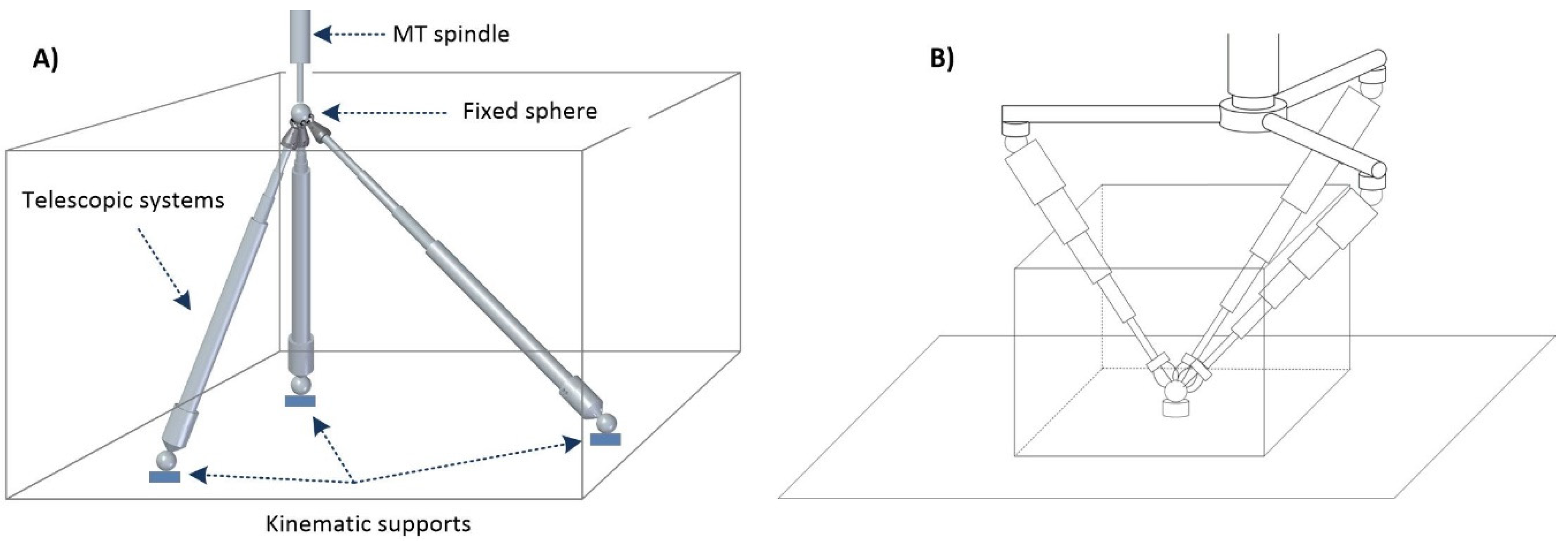
- Telescopic arms. The system designed comprises initially three telescopic arms. Each telescopic arm (Figure 1) has a conventional kinematic support at one end that allows it to register and rotate with respect to a point on the MT table. A coupling based on a ferromagnetic sphere has been defined, which is attached to one end of the telescopic arm with a conventional magnetic holder fixed to the table. In this way, the magnetic holders allow the free rotation of the sphere through a ball-joint type with the least possible friction and preventing all the displacements.For the connection of the telescopic arms to the MT, a common ferromagnetic sphere is used, which is attached to the MT spindle nose. Each arm rotates freely with respect to its kinematic coupling with the minimum possible friction to enable the required movements without collision among the fingers of the multipoint kinematic couplings (tridents). In addition, the arms can be extended with their telescopic system with the minimum possible friction and have sufficient rigidity to enable high precision measurements.
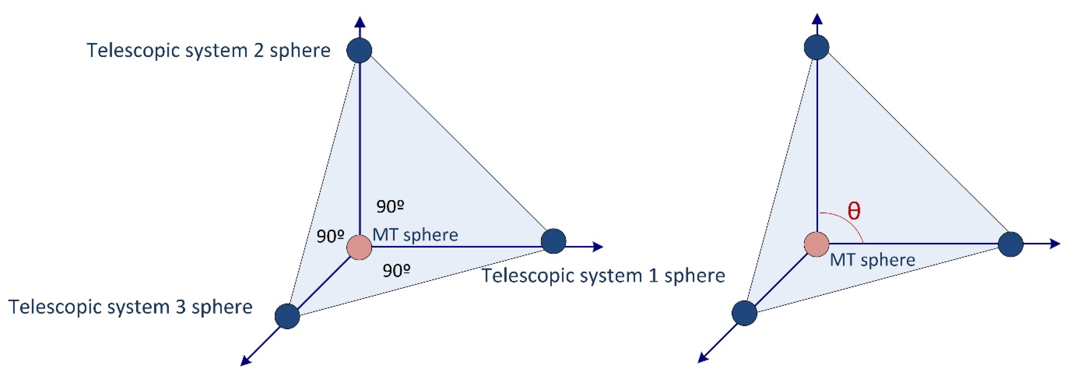
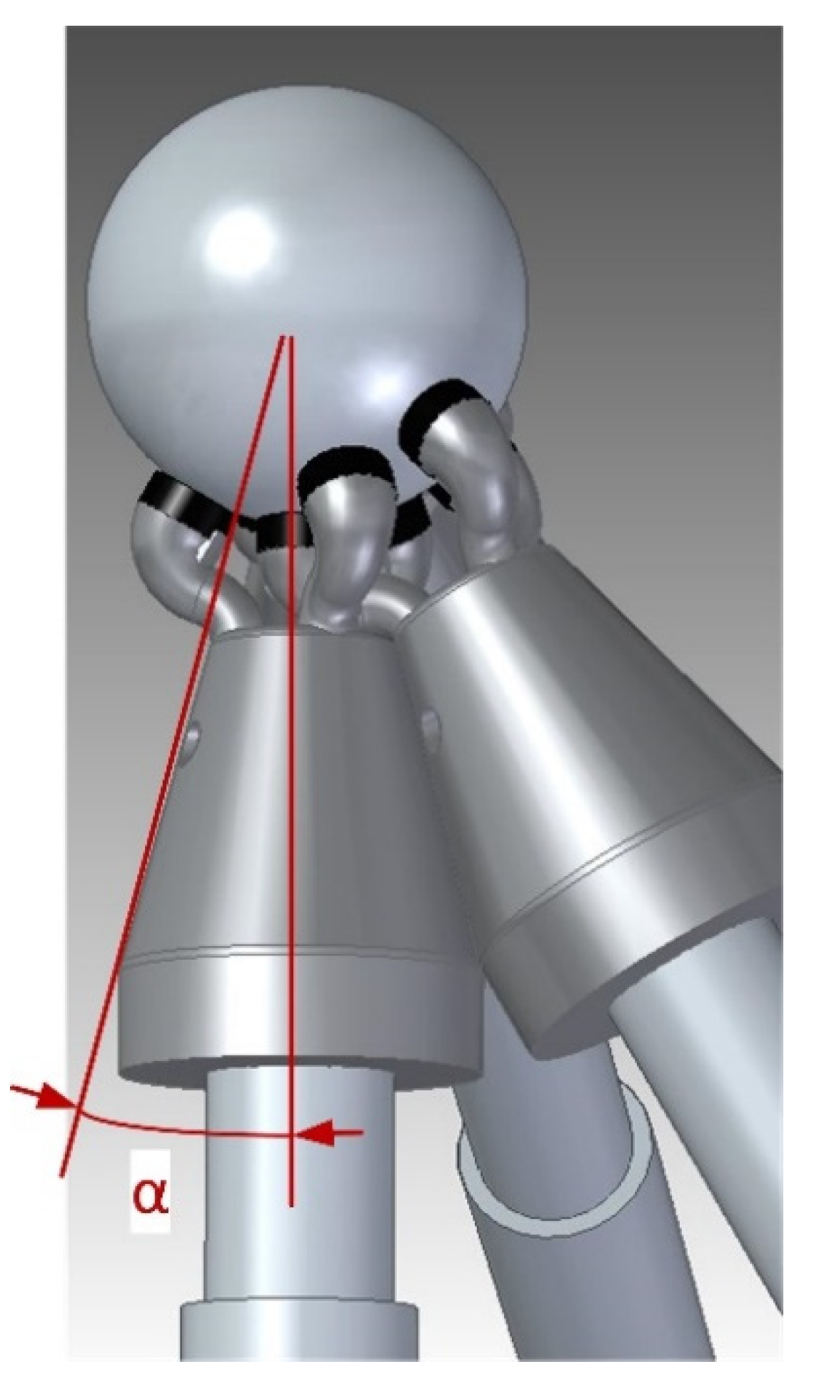
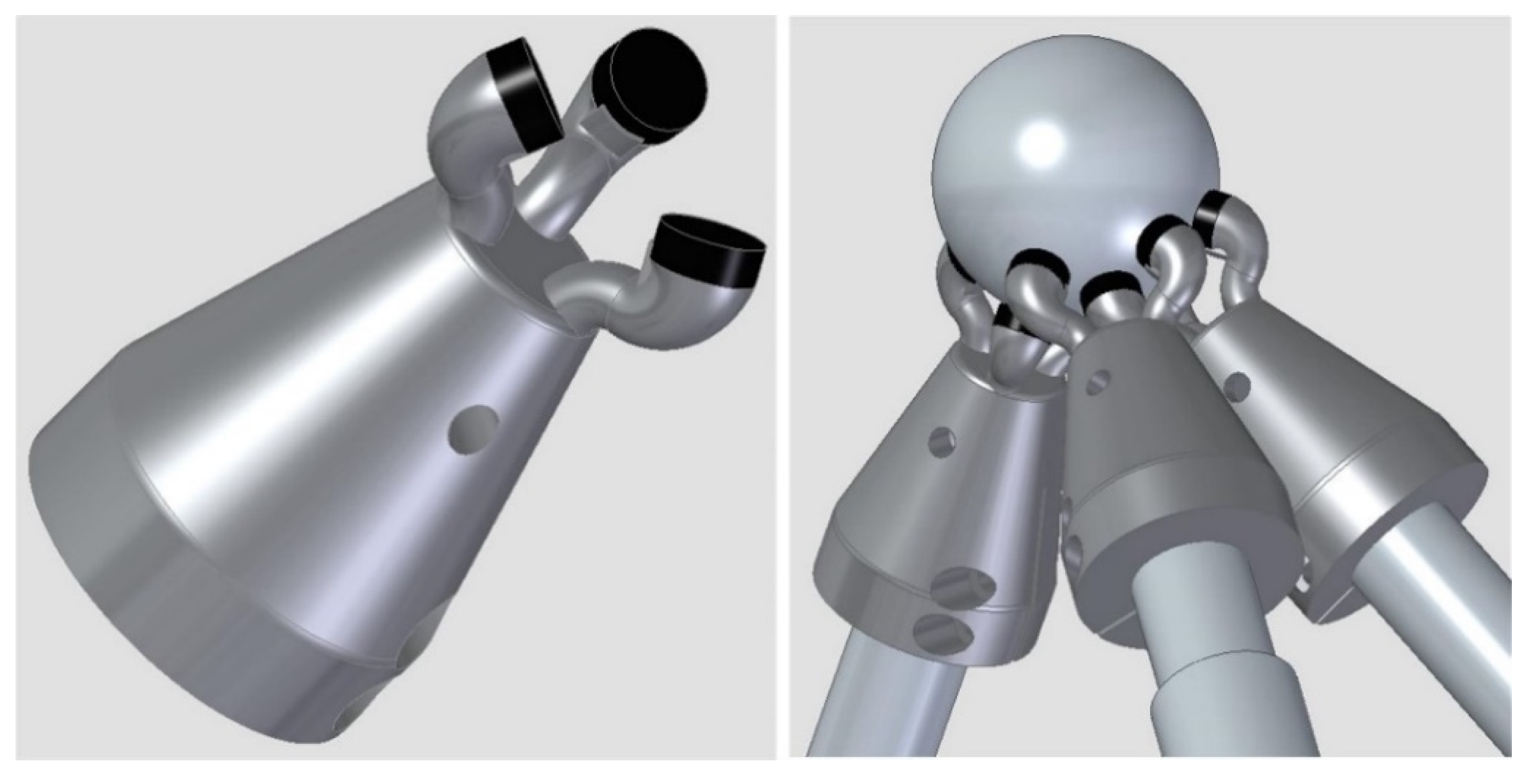
- Trident: on the other side of each telescopic arm, a multipoint kinematic coupling allows the registration and rotation with respect to another point. In this case, it enables several telescopic arms to be registered and rotate simultaneously and independently with respect to the same point, see (Figure 1). Thanks to the design of this kinematic coupling, each arm is in contact with the ball anchored to the machine spindle nose. The coupling is a trident system consisting of three fingers that contact the sphere at three points, with the arms forming a desirable relative angle of 90° from the center of the sphere. This allows continuous and precise registration with respect to the center of the sphere and the coexistence with the other tridents of the arms avoiding possible collisions. The connection between the trident and the sphere anchored to the MT spindle nose is made by means of magnetic systems. They are located on the upper part of each trident’s finger, enabling the required free movement. The magnetic systems make it possible not only to maintain an attraction force with respect to the fixed sphere to avoid its separation, but also generate a repulsion force among the fingers of different tridents to avoid their contact or collision. In this way, their relative rotation is permitted, adjusting themselves to the required trajectories without hindering its operation.
- Laser measuring system. The telescopic arms have a laser measurement system by interferometry with the emitting head at one end and a retroreflector at the end close to the sphere fixed to the MT spindle nose (Figure 1). The laser system, with characteristics summarized in Table 1, measures directly the relative displacement between the sphere attached to the MT spindle nose and the sphere fixed in the magnetic holder located on the MT table. It measures in an incremental way from a reference position that is materialized in a calibration gauge [37] by means of a fixed magnetic sphere-holder that locks the position of the sphere fixed to the instrument. The gauge is designed with several kinematic supports to obtain a repeatable positioning of a movable sphere that materializes the different calibration lengths of the telescopic arm.
2.3. Design Parameters
2.3.1. Telescopic Systems Angle
2.3.2. Telescopic System Arms Length
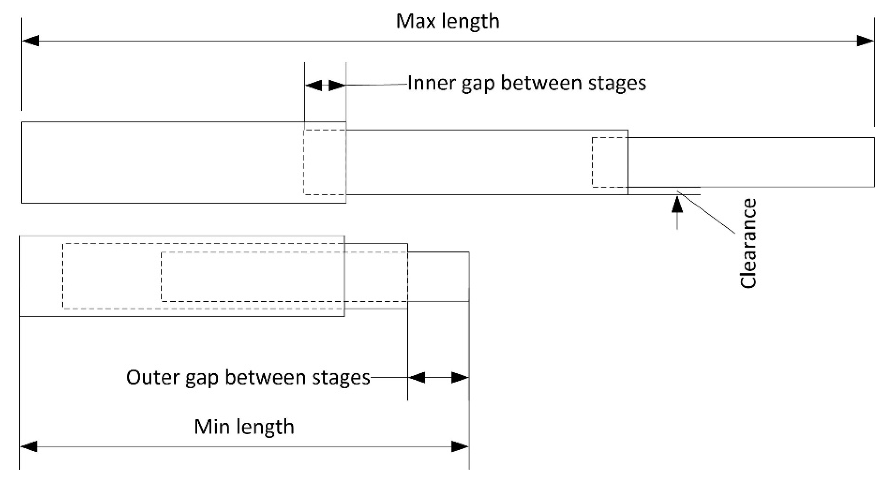
- Maximum (Lmax) and minimum length (Lmin): length that reaches the telescopic arm in its most extended and retracted position.
- Effective measuring range (ΔL): range that the telescopic arm can be extended. It is calculated as the difference between the maximum and minimum length.
- Stages (n): each of the sections that the telescopic arm is divided into, which can be extended by moving them with respect to the previous one. They are numbered from the stage that in the retracted position holds all the others.
- Stage length (Li): length of each of the n-stages of the tube. It is the same in all of them.
- Effective stage length (Lief): difference between the stage length (Li) and the inner gap between stages (Innergap).
- Inner gap between stages (Innergap): minimum length that a stage remains embedded in the previous stage to minimize the radial clearance between stages.
- Outer gap between stages (Outergap): length that exceeds one stage in relation to the previous one when it is retracted.
- Clearance (c): gap between stages in the radial direction.
2.3.3. Tridents Magnets and Sphere Diameter Relation
3. Prototype Assembling of the High Precision Telescopic System
4. Discussion
- The main advantage of the system is that it allows data capture in a single cycle. This is possible because of the simultaneous operation of the three telescopic arms that are registered simultaneously to a sphere fixed on the MT by means of a newly developed multipoint kinematic coupling (trident).
- There are two concepts developed for the fixation and positioning of the system in the MT. The conventional one includes a fixed sphere on the MT spindle nose and the telescopic system supported on the MT table. The second inverted positioning has the fixed part of the telescopic arms suspended from the MT spindle nose and the fixed sphere located on the MT table. This last set-up allows the verification of the MT rotating axes in a more convenient way.
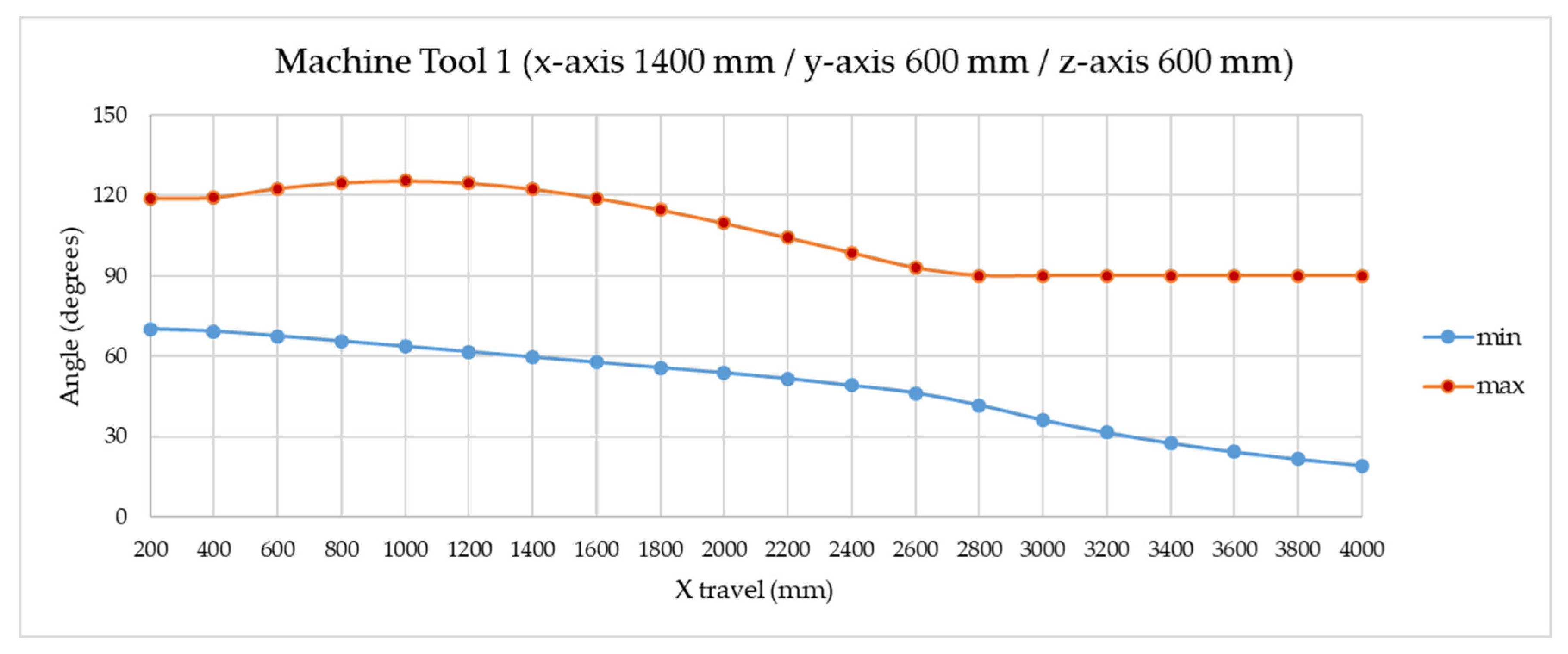
- In relation with the angle between the telescopic systems in the MTs verification, this study reveals: (i) the fixed points of support of the arms must be arranged in such a way that the angles between the arms are centered at 90 degrees, which is desirable for the precise operation of the multilateration, with maximum values of around 120° and minimum values of 60°; (ii) as the x-travel increases, the minimum angle decreases; (iii) an angle of 15° on the trident body makes it possible to work in a single cycle with verification volumes on machines with unbalanced travels, such as up to 3200 × 600 × 600 mm.
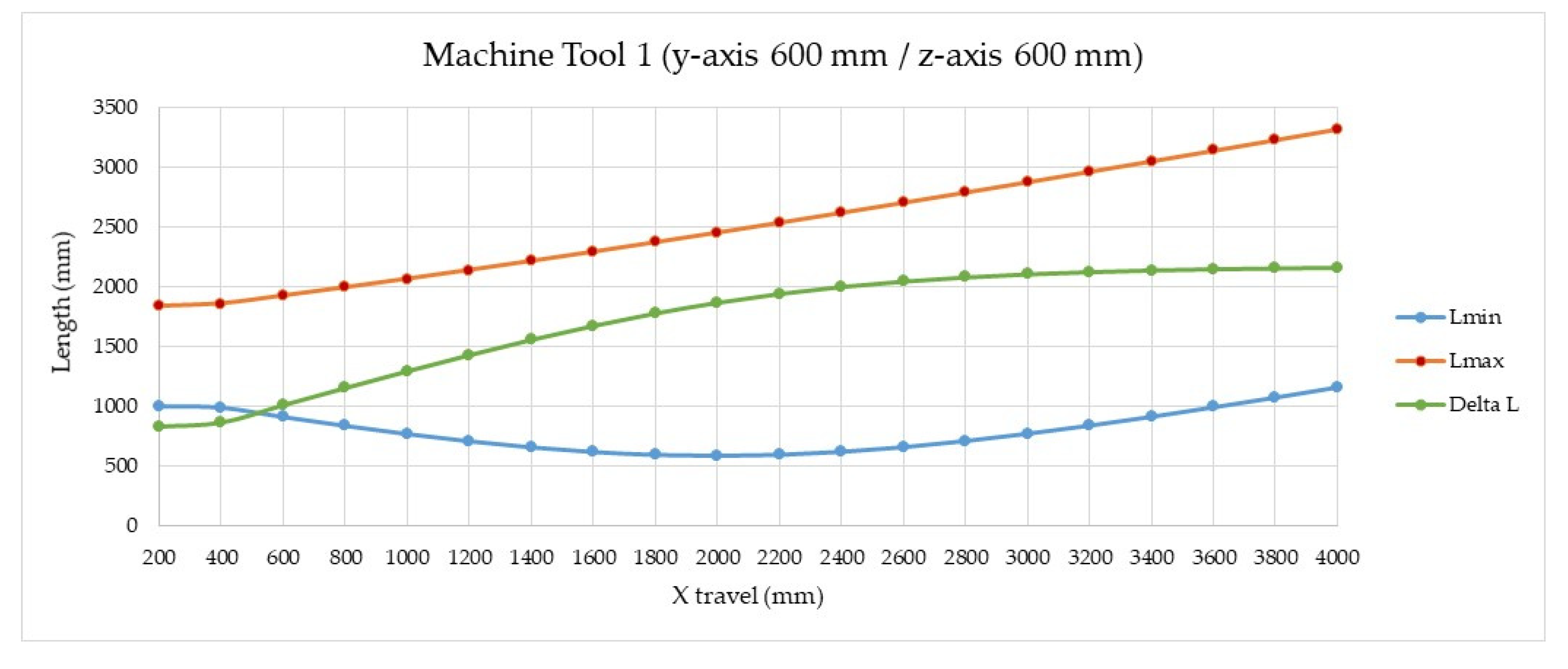
- Differences have been observed between the telescopic system requirements for small and medium-sized machine tools concerning the telescopic arm length. For machine tool 1, its working volume could be verified with a telescopic system with 5 stages (n), stage length (Li) of 500 mm, and 400 mm effective length (Lief). The maximum (Lmax) and minimum (Lmin) lengths of the complete telescopic arm would be 2254 and 654 mm, respectively, with an effective measuring range (ΔL) of 1600 mm. It is noted that to verify machines with travels greater than 1400 mm, more stages need to be incorporated into the telescopic arm. For MT 2, a 5-stage telescopic system (n) is proposed, with stage length (Li) of 223.5 mm and effective length (Lief) of 146.3 mm. This design presents maximum (Lmax) and minimum (Lmin) arm lengths of 960 and 375 mm, respectively, with effective measuring range (ΔL) of 585 mm, which would be sufficient for the verification volume of the small machine.
- Minimizing the misalignment of the telescopic arm was considered as a requirement in its design, due to its influence on the alignment of the measuring system. To this end, the influence of the radial clearance between stages and the effect of the arm’s own bending on its extension were evaluated.
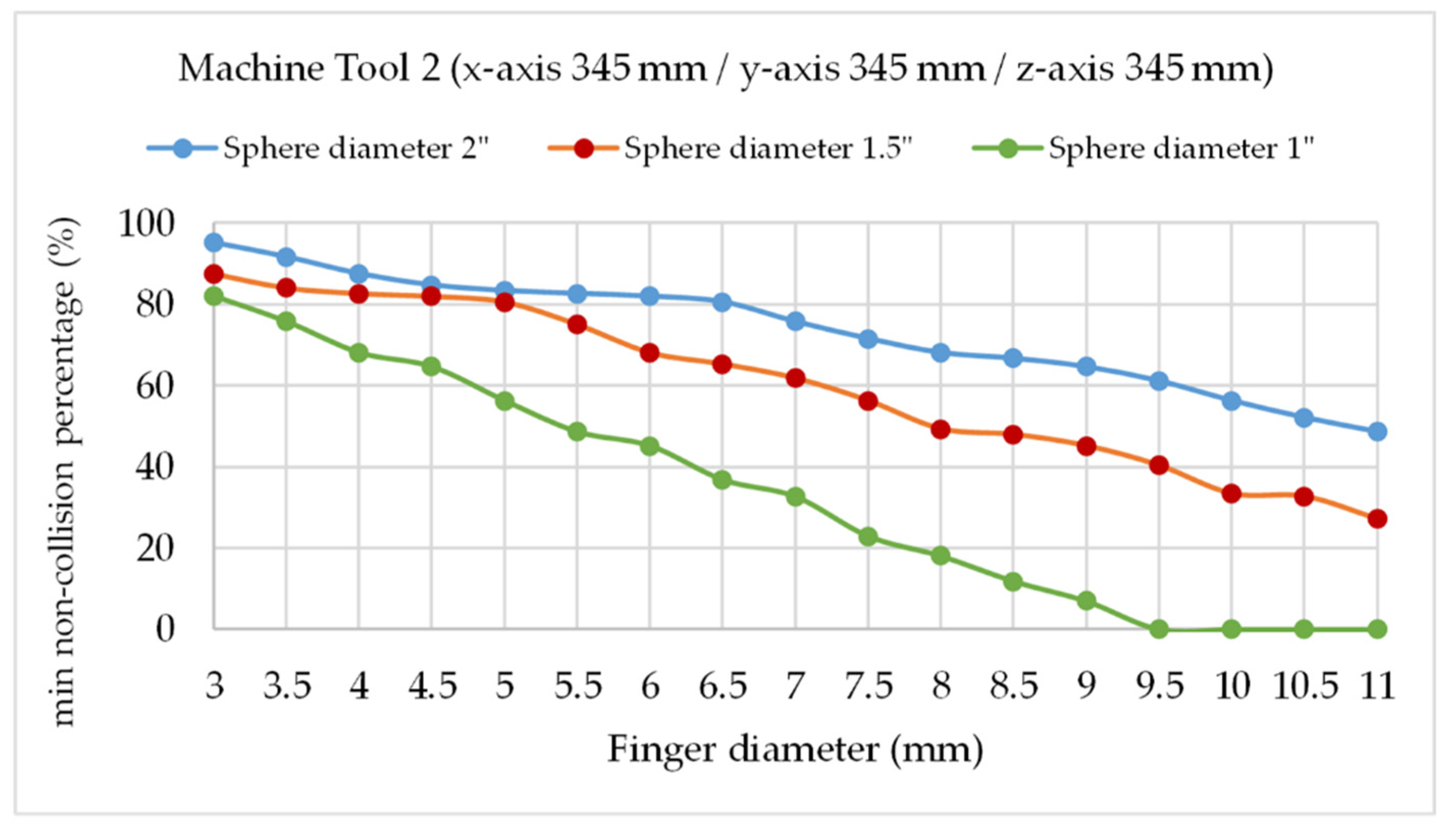
- It is extremely important for the precise positioning of the arms on the sphere and to avoid collisions between the kinematic couplings, the correct selection of the magnetic system on the trident fingers and its relation to the size of the fixed registration sphere in the MT spindle nose. In the first prototype design, applicable in this case for both MT sizes, we considered a fixed sphere of 1.5′′ diameter and trident’s finger diameter of 8 mm, selecting a cylindrical neodymium magnet of 6.5 mm diameter and 3 mm height because of magnetic force requirements considering the dynamics and the weight of the system.
Author Contributions
Funding
Acknowledgments
Conflicts of Interest
References
- Schwenke, H.; Knapp, W.; Haitjema, H.; Weckenmann, A.; Schmitt, R.; Delbressine, F. Geometric error measurement and compensation of machines—An update. CIRP Ann. 2008, 57, 660–675. [Google Scholar] [CrossRef]
- International Organization for Standardization ISO 230-1:2012. Test Code for Machine Tools—Part 1: Geometric Accuracy of Machines Operating under No-Load or Quasi-Static Conditions; ISO: Geneva, Switzerland, 2012. [Google Scholar]
- Kunzmann, H.; Trapet, E.; Wäldele, F. A uniform concept for calibration, acceptance test, and periodic inspection of coordinate measuring machines using reference objects. CIRP Ann. Technol. 1990, 39, 561–564. [Google Scholar] [CrossRef]
- Zargarbashi, S.H.H.; Mayer, J.R.R. Assessment of machine tool trunnion axis motion error, using magnetic double ball bar. Int. J. Mach. Tools Manuf. 2006, 46, 1823–1834. [Google Scholar] [CrossRef]
- Belforte, G.; Bona, B.; Canuto, E.; Donati, F.; Ferraris, F.; Gorini, I.; Morei, S.; Peisino, M.; Sartori, S.; Levi, R. Coordinate measuring machines and machine tools selfcalibration and error correction. CIRP Ann. Technol. 1987, 36, 359–364. [Google Scholar] [CrossRef]
- Ibaraki, S.; Kudo, T.; Yano, T.; Takatsuji, T.; Osawa, S.; Sato, O. Estimation of three-dimensional volumetric errors of machining centers by a tracking interferometer. Precis. Eng. 2015, 39. [Google Scholar] [CrossRef] [Green Version]
- Aguado, S.; Santolaria, J.; Samper, D.; Aguilar, J.J.; Velázquez, J. Improving a real milling machine accuracy through an indirect measurement of its geometric errors. J. Manuf. Syst. 2016, 40, 26–36. [Google Scholar] [CrossRef]
- Aguado, S.; Samper, D.; Santolaria, J.; Aguilar, J.J. Towards an effective identification strategy in volumetric error compensation of machine tools. Meas. Sci. Technol. 2012, 23. [Google Scholar] [CrossRef]
- Pahk, H.J.; Kim, Y.S.; Moon, J.H. A new technique for volumetric error assessment of CNC machine tools incorporating ball bar measurement and 3D volumetric error model. Int. J. Mach. Tools Manuf. 1997, 37, 1583–1596. [Google Scholar] [CrossRef]
- Zhong, L.; Bi, Q.; Wang, Y. Volumetric accuracy evaluation for five-axis machine tools by modeling spherical deviation based on double ball-bar kinematic test. Int. J. Mach. Tools Manuf. 2017, 122, 106–119. [Google Scholar] [CrossRef]
- Xu, K.; Li, G.; He, K.; Tao, X. Identification of position-dependent geometric errors with non-integer exponents for Linear axis using double ball bar. Int. J. Mech. Sci. 2020, 170, 105326. [Google Scholar] [CrossRef]
- Fan, K.-C.; Wang, H.; Shiou, F.-J.; Ke, C.-W. Design analysis and applications of a 3D laser ball bar for accuracy calibration of multiaxis machines. J. Manuf. Syst. 2004, 23, 194–203. [Google Scholar] [CrossRef]
- Schwenke, H.; Warmann, C. High Speed High Accuracy Multilateration System Based on Tracking Interferometers. In Proceedings of the 10th IMEKO TC14 Symposium on Laser Metrology for Precision Measurement and Inspection in Industry, Braunschweig, Germany, 12–14 September 2011. [Google Scholar]
- Uekita, M.; Takaya, Y. On-machine dimensional measurement of large parts by compensating for volumetric errors of machine tools. Precis. Eng. 2016, 43, 200–210. [Google Scholar] [CrossRef]
- Ezedine, F.; Linares, J.-M.; Sprauel, J.-M.; Chaves-Jacob, J. Smart sequential multilateration measurement strategy for volumetric error compensation of an extra-small machine tool. Precis. Eng. 2016, 43, 178–186. [Google Scholar] [CrossRef]
- Wang, Z.; Maropolous, P.G. Real-time error compensation of a three-axis machine tool using a laser tracker. Int. J. Adv. Manuf. Technol. 2013, 69, 919–933. [Google Scholar] [CrossRef]
- Wang, J.; Guo, J. The identification method of the relative position relationship between the rotary and linear axis of multi-axis numerical control machine tool by laser tracker. Measurement 2019, 132, 369–376. [Google Scholar] [CrossRef] [Green Version]
- Mori, M.; Irino, N.; Shimoike, M. A new measurement method for machine tool thermal deformation on a two-dimensional trajectory using a tracking interferometer. CIRP Ann. 2019, 68, 551–554. [Google Scholar] [CrossRef]
- Muralikrishnan, B.; Phillips, S.; Sawyer, D. Laser trackers for large-scale dimensional metrology: A review. Precis. Eng. 2016, 44, 13–28. [Google Scholar] [CrossRef]
- Ibaraki, S.; Hata, T.; Matsubara, A. A new formulation of laser step-diagonal measurement-two-dimensional case. Precis. Eng. 2009, 33, 56–64. [Google Scholar] [CrossRef] [Green Version]
- Hughes, B.; Forbes, A.; Lewis, A.; Sun, W.; Veal, D.; Nasr, K. Laser tracker error determination using a network measurement. Meas. Sci. Technol. 2011, 22. [Google Scholar] [CrossRef]
- Balsamo, A.; Pedone, P.; Ricci, E.; Verdi, M. Low-cost interferometric compensation of geometrical errors. CIRP Ann. Manuf. Technol. 2009, 58, 459–462. [Google Scholar] [CrossRef]
- Muralikrishnan, B.; Sawyer, D.; Blackburn, C.; Phillips, S.; Borchardt, B.; Estler, W.T. ASME B89.4.19 Performance Evaluation Tests and Geometric Misalignments in Laser Trackers. J. Res. Natl. Inst. Stand. Technol. 2009, 114, 21. [Google Scholar] [CrossRef]
- Ouyang, J.; Liu, W.; Qu, X.; Yan, Y. Modeling and self-calibration of laser tracker systems using planar constraints. In Proceedings of the ASPE, Dallas, TX, USA, 14–19 October 2007; pp. 1–4. [Google Scholar]
- Chen, X.; Zhang, G.X.; Zhao, S.Z.; Duan, F.J. Analysis and measurement for the optical error of the Cat’s eye retro-reflector. J. Phys. Conf. Ser. 2006, 48, 64–68. [Google Scholar] [CrossRef]
- Gallagher, B.B. Optical Shop Applications for Laser Tracking Metrology Systems; University of Arizona: Tucson, AZ, USA, 2003. [Google Scholar]
- Teoh, P.L.; Shirinzadeh, B.; Foong, C.W.; Alici, G. The measurement uncertainties in the laser interferometry-based sensing and tracking technique. Measurement 2002, 32, 135–150. [Google Scholar] [CrossRef]
- Zhang, Z.; Hu, H. Measurement and compensation of geometric errors of three-axis machine tool by using laser tracker based on a sequential multilateration scheme. Proc. Inst. Mech. Eng. Part B J. Eng. Manuf. 2014, 228, 819–831. [Google Scholar] [CrossRef]
- Lee, M.C.; Ferreira, P.M. Auto-triangulation and auto-trilateration. Part 1. Fundamentals. Precis. Eng. 2002, 26, 237–249. [Google Scholar] [CrossRef]
- Wendt, K.; Franke, M.; Härtig, F. Measuring large 3D structures using four portable tracking laser interferometers. Meas. J. Int. Meas. Confed. 2012, 45, 2339–2345. [Google Scholar] [CrossRef]
- Wang, J.; Guo, J.; Zhou, B.; Xiao, J. The detection of rotary axis of NC machine tool based on multi-station and time-sharing measurement. Meas. J. Int. Meas. Confed. 2012, 45, 1713–1722. [Google Scholar] [CrossRef]
- Takatsuji, T.; Goto, M.; Kirita, A.; Kurosawa, T.; Tanimura, Y. The relationship between the measurement error and the arrangement of laser trackers in laser trilateration. Meas. Sci. Technol. 2000, 11, 477. [Google Scholar] [CrossRef]
- Aguado, S.; Santolaria, J.; Samper, D.; Aguilar, J.J. Influence of measurement noise and laser arrangement on measurement uncertainty of laser tracker multilateration in machine tool volumetric verification. Precis. Eng. 2013, 37, 929–943. [Google Scholar] [CrossRef]
- Linares, J.M.; Chaves-Jacob, J.; Schwenke, H.; Longstaff, A.; Fletcher, S.; Flore, J.; Uhlmann, E.; Wintering, J. Impact of measurement procedure when error mapping and compensating a small CNC machine using a multilateration laser interferometer. Precis. Eng. 2014, 38, 578–588. [Google Scholar] [CrossRef]
- ETALON. Etalon X-AX LASERBAR. The System Solution for Calibration, Compensation and Verification of Small and Middle Size Machine Tools. Available online: https://www.etalonproducts.com/wp-content/uploads/pdf/Hexagon-Etalon-X-AX_Laserbar-Brochure-EN-1.pdf (accessed on 7 July 2020).
- Jutta Thiel Squeezing out the last micron. Optik Photonics 2014, 2, 55–57.
- Brosed, F.J.; Cacho, R.A.; Aguado, S.; Herrer, M.; Aguilar, J.J.; Mazo, J.S. Development and validation of a calibration gauge for length measurement systems. Materials 2019, 12, 3960. [Google Scholar] [CrossRef] [PubMed] [Green Version]




| Device | Item | Value | Unit |
|---|---|---|---|
| Machine tool 1 | Type | 3-axis vertical mill | |
| Travel range X axis | 1400 | mm | |
| Travel range Y axis | 600 | mm | |
| Travel range Z axis | 600 | mm | |
| Machine tool 2 | Type | 5 axis vertical mill | |
| Travel range X axis | 345 | mm | |
| Travel range Y axis | 345 | mm | |
| Travel range Z axis | 345 | mm | |
| Rotary axis | A/C | ||
| Displacement measuring interferometer | Type | IDS3010 | |
| DFB laser (infrared) | 1530 | nm | |
| Number of axes | 3 | ||
| Working distance | 5 | m | |
| Max target velocity | 2 | m/s | |
| Resolution | 1 | pm |
| Verification Points | 1 | 2 | 3 | 4 | 5 | 6 | 7 | 8 | 9 | ||
|---|---|---|---|---|---|---|---|---|---|---|---|
| θ12 (°) | 90.0 | 82.7 | 74.2 | 122.4 | 108.1 | 61.0 | 59.7 | 72.9 | 69.7 | 122.4 | max |
| θ23 (°) | 90.0 | 62.0 | 70.5 | 75.4 | 98.0 | 62.0 | 70.5 | 75.4 | 98.0 | 59.7 | min |
| θ31 (°) | 90.0 | 61.0 | 59.7 | 72.9 | 69.7 | 82.7 | 74.2 | 122.4 | 108.1 |
© 2020 by the authors. Licensee MDPI, Basel, Switzerland. This article is an open access article distributed under the terms and conditions of the Creative Commons Attribution (CC BY) license (http://creativecommons.org/licenses/by/4.0/).
Share and Cite
Aguilar, J.J.; Acero, R.; Brosed, F.J.; Santolaria, J. Development of a High Precision Telescopic Instrument Based on Simultaneous Laser Multilateration for Machine Tool Volumetric Verification. Sensors 2020, 20, 3798. https://doi.org/10.3390/s20133798
Aguilar JJ, Acero R, Brosed FJ, Santolaria J. Development of a High Precision Telescopic Instrument Based on Simultaneous Laser Multilateration for Machine Tool Volumetric Verification. Sensors. 2020; 20(13):3798. https://doi.org/10.3390/s20133798
Chicago/Turabian StyleAguilar, Juan José, Raquel Acero, Francisco Javier Brosed, and Jorge Santolaria. 2020. "Development of a High Precision Telescopic Instrument Based on Simultaneous Laser Multilateration for Machine Tool Volumetric Verification" Sensors 20, no. 13: 3798. https://doi.org/10.3390/s20133798
APA StyleAguilar, J. J., Acero, R., Brosed, F. J., & Santolaria, J. (2020). Development of a High Precision Telescopic Instrument Based on Simultaneous Laser Multilateration for Machine Tool Volumetric Verification. Sensors, 20(13), 3798. https://doi.org/10.3390/s20133798


