Research on the Gravity Disturbance Compensation Terminal for High-Precision Position and Orientation System

Abstract
:1. Introduction
2. High-Precision Gravity Database
2.1. GGMplus
2.2. High-Precision Gravity Database for Inertial Measurement
2.3. Accuracy Evaluation of Gravity Database
3. B-TV-MM
4. Gravity Disturbance Compensation Device
4.1. Design Principles
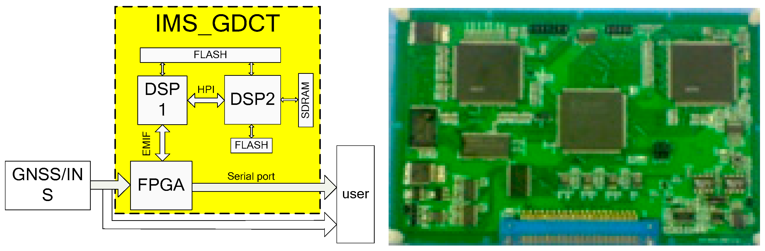
4.2. Design Scheme
4.3. Hardware Design
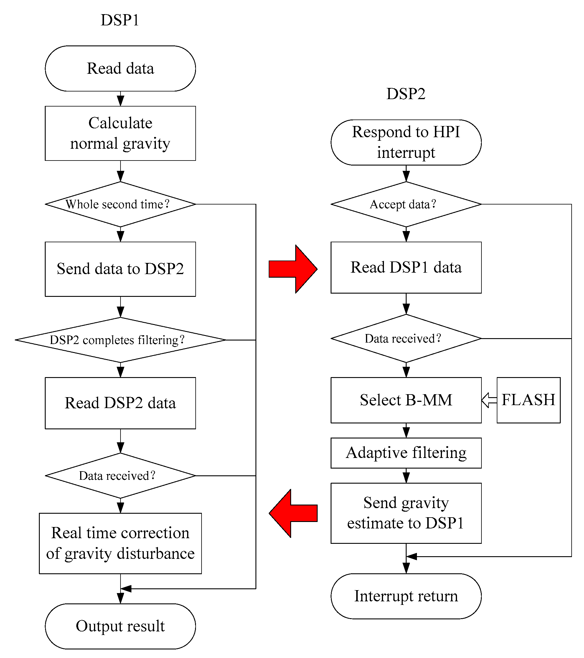
4.4. Algorithm Flow
4.5. Structural Design
5. Experiment
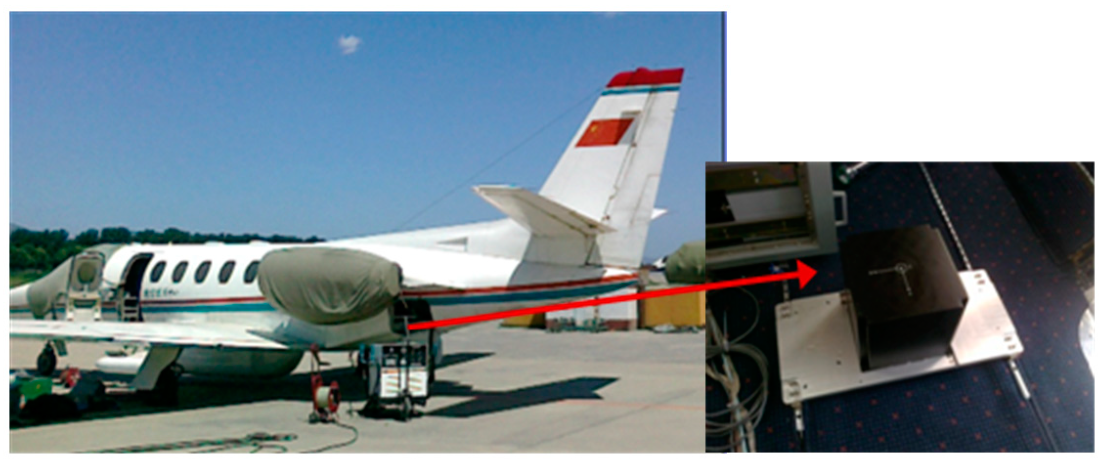
5.1. Experiment Equipment
5.2. The Plan of Flight Experiment
5.3. Data Analysis and Results
6. Conclusions
Author Contributions
Funding
Conflicts of Interest
References
- Gautam, D.; Lucieer, A.; Watson, C.; McCoull, C. Lever-arm and Boresight Correction, and Field of View Determination of a Spectroradiometer Mounted on an Unmanned Aircraft System. ISPRS J. Photogramm. Remote Sens. 2019, 155, 25–36. [Google Scholar] [CrossRef]
- Fu, X.K.; Xiang, M.S.; Wang, B.N. A Robust Yaw and Pitch Estimation Method for Mini-InSAR System. IEEE Geosci. Remote Sens. Lett. 2017, 14, 2157–2161. [Google Scholar] [CrossRef]
- Lima, C.F.A.; Mitishita, E.A. An Approach to Improve Direct Sensor Orientation Using the Integration of Photogrammetric and Lidar Datasets. Int. J. Remote Sens. 2019, 40, 5651–5672. [Google Scholar]
- Zhong, M.; Cao, Q.; Guo, J.; Zhou, D. Simultaneous Lever-Arm Compensation and Disturbance Attenuation of POS for a UAV Surveying System. IEEE Trans. Instrum. Meas. 2016, 65, 2828–2839. [Google Scholar] [CrossRef]
- Fang, J.C.; Gong, X.L. Predictive Iterated Kalman Filter for INS/GPS Integration and Its Application to SAR Motion Compensation. IEEE Trans. Instrum. Meas. 2010, 59, 909–915. [Google Scholar] [CrossRef]
- Zhu, Z.S.; Li, C.; Zhou, X.Y. An Accurate High-Order Errors Suppression and Cancellation Method for High-Precision Airborne POS. IEEE Trans. Geosci. Remote Sens. 2018, 56, 357–5367. [Google Scholar] [CrossRef]
- Fang, J.C.; Chen, L.Z.T.; Yao, J.F. An Accurate Gravity Compensation Method for High-Precision Airborne POS. IEEE Trans. Geosci. Remote Sens. 2014, 52, 4564–4573. [Google Scholar] [CrossRef]
- Chang, L.B.; Li, J.S.; Chen, S.Y. Initial Alignment by Attitude Estimation for Strapdown Inertial Navigation Systems. IEEE Trans. Instrum. Meas. 2015, 64, 784–794. [Google Scholar] [CrossRef]
- Zhu, Z.S.; Zhao, B.; Guo, Y.Y. Research on Gravity Vertical Deflection on Attitude of Position and Orientation System and Compensation Method. Aerosp. Sci. Technol. 2019, 85, 495–504. [Google Scholar] [CrossRef]
- Li, J.L.; Fang, J.C.; Du, M. Error Analysis and Gyro-Bias Calibration of Analytic Coarse Alignment for Airborne POS. IEEE Trans. Instrum. Meas. 2012, 61, 3058–3064. [Google Scholar]
- Deng, Z.H.; Sun, M.; Wang, B. Analysis and Calibration of the Nonorthogonal Angle in Dual-Axis Rotational INS. IEEE Trans. Ind. Electron. 2017, 64, 4762–4771. [Google Scholar] [CrossRef]
- Hu, P.D.; Xu, P.; Chen, B.X. A Self-Calibration Method for the Installation Errors of Rotation Axes Based on the Asynchronous Rotation of Rotational Inertial Navigation Systems. IEEE Trans. Ind. Electron. 2018, 65, 3550–3558. [Google Scholar] [CrossRef]
- Chang, L.B.; Qin, F.J.; Wu, M.P. Gravity Disturbance Compensation for Inertial Navigation System. IEEE Trans. Instrum. Meas. 2019, 68, 3751–3765. [Google Scholar] [CrossRef]
- Zhu, Z.S.; Guo, Y.Y. A Real-time Gravity Compensation Method for High-PrecisionAirbrone POS based on Gravity map. J. Navig. 2018, 71, 711–728. [Google Scholar] [CrossRef]
- Hirt, C.; Claessens, S.; Fecher, T.; Kuhn, M.; Pail, R.; Rexer, M. New Ultrahigh-resolution Picture of Earth’s Gravity Field. Geophys. Res. Lett. 2013, 40, 4279–4283. [Google Scholar] [CrossRef] [Green Version]
- Tie, J.B.; Cao, J.L.; Chang, L.B. A Model of Gravity Vector Measurement Noise for Estimating Accelerometer Bias in Gravity Disturbance Compensation. Sensors 2018, 18, 883. [Google Scholar] [CrossRef] [Green Version]
- Zhou, X.; Yang, G.L.; Wang, J. A Combined Gravity Compensation Method for INS Using the Simplified Gravity Model and Gravity Database. Sensors 2018, 18, 1552. [Google Scholar] [CrossRef] [Green Version]
- Wang, B.; Zhu, J.W.; Deng, Z.H. A Characteristic Parameter Matching Algorithm for Gravity-Aided Navigation of Underwater Vehicles. IEEE Trans. Ind. Electron. 2019, 66, 1203–1212. [Google Scholar] [CrossRef]
- Onizawa, S. Apparent Calibration Shift of the Scintrex CG-5 Gravimeter Caused by Reading-dependent Scale Factor and Instrumental Drift. J. Geod. 2019, 93, 1335–1345. [Google Scholar] [CrossRef]
- Gietka, K.; Mivehvar, F.; Ritsch, H. Supersolid-Based Gravimeter in a Ring Cavity. Phys. Rev. Lett. 2019, 122, 190801. [Google Scholar] [CrossRef] [Green Version]
- Lee, S.G. A Full-Tensor Superconducting Gravity Gradiometer System Composed of Levitation-Type Accelerometers. J. Korean Phys. Soc. 2019, 75, 254–260. [Google Scholar] [CrossRef]
- Griggs, C.E.; Moody, M.V.; Norton, R.S.; Paik, H.J.; Venkateswara, K. Sensitive Superconducting Gravity Gradiometer Constructed with Levitated Test Masses. Phys. Rev. Appl. 2017, 8, 064024. [Google Scholar] [CrossRef] [Green Version]
- Yu, M.B.; Cai, T.J. Online error compensation of moving-base rotating accelerometer gravity gradiometer. Rev. Sci. Instrum. 2019, 90, 074501. [Google Scholar] [CrossRef] [PubMed]
- Kryuchkov, Y.L. A linear superconducting suspension for a gravity-inertial instrument. Instrum. Exp. Tech. 2008, 51, 443–447. [Google Scholar] [CrossRef]
- Sokolov, A.V.; Krasnov, A.A.; Konovalov, A.B. Measurements of the Acceleration of Gravity on Board of Various Kinds of Aircraft. Meas. Tech. 2016, 59, 565–570. [Google Scholar] [CrossRef]
- Jacoby, W.; Smilde, P.L. Gravity Interpretation; Springer: Berlin/Heidelberg, Germany, 2009. [Google Scholar]
- Rummel, R. Height unification using GOCE. J. Geod. Sci. 2012, 2, 355–362. [Google Scholar] [CrossRef]
- Featherstone, W.E. GNSS-based heighting in Australia: Current, emerging and future issues. J. Spat. Sci. 2018, 53, 115–133. [Google Scholar] [CrossRef] [Green Version]
- Applanix POS/AV Specification [EB/OL] 2012 [2013-11-21]. Available online: https://www.applanix.com/products/posav.htm (accessed on 10 March 2018).


| Gravity Disturbance Error (mGal) | Attitude Error (°) | Gravity Disturbance Error (mGal) | Attitude Error (°) |
|---|---|---|---|
| 1 | 0.00011 | 20 | 0.0023 |
| 5 | 0.00059 | 25 | 0.0029 |
| 10 | 0.0012 | 30 | 0.0035 |
| 15 | 0.0018 | 35 | 0.0041 |
| POS/AV610 | C/A GPS | RTK | Post-Processing |
|---|---|---|---|
| Roll and Pitch (°) | 0.005 | 0.005 | 0.0025 |
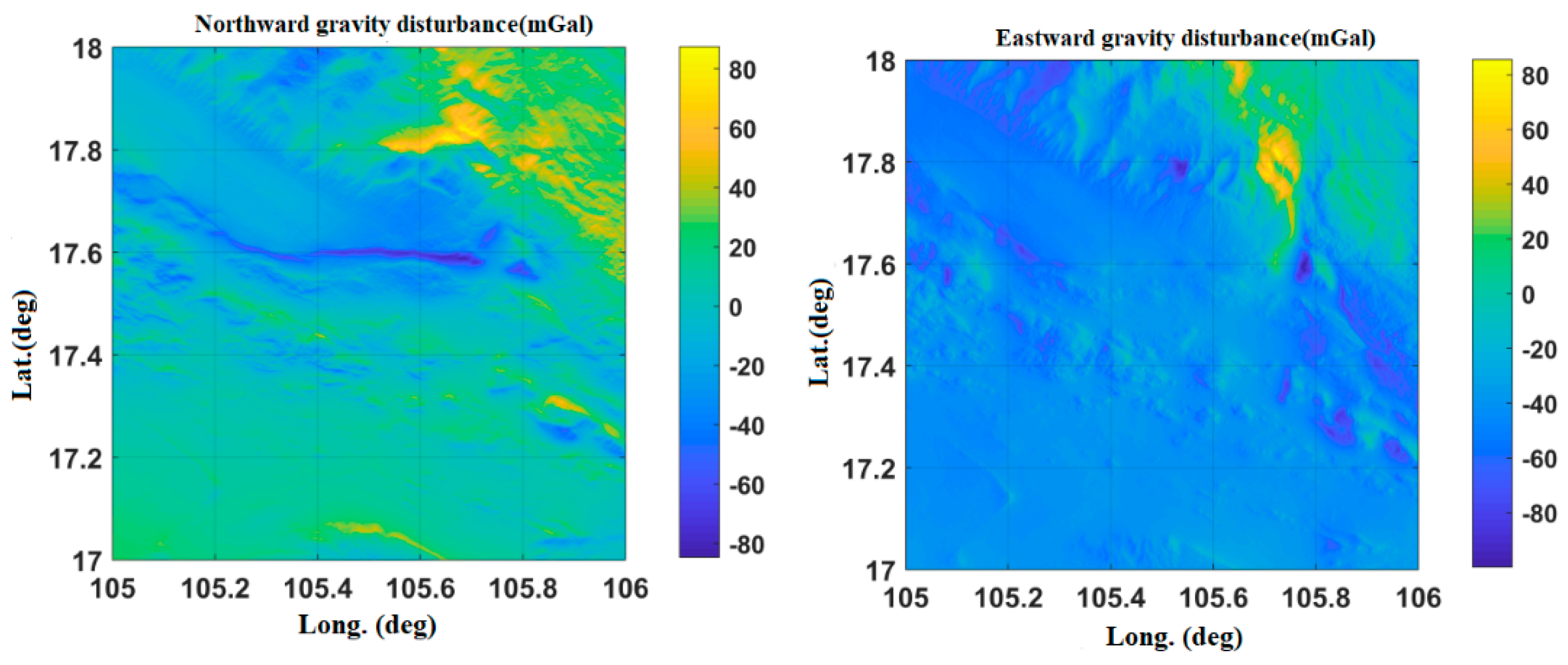
| Gravity Disturbance Data Source | Mean Value (mGal) | Variance | Proportion of Effective Forecast Data | |
|---|---|---|---|---|
| Northward gravity disturbance | Datum points | −45.33 | 16.6382 | 96.2% |
| Interpolation points | −44.87 | 15.9361 | ||
| Eastward gravity disturbance | Datum points | −24.83 | 9.2472 | |
| Interpolation points | −25.35 | 10.7153 | ||
| Gravity Disturbance Data Source | Mean Value (mGal) | Variance | Proportion of Effective Forecast Data | |
|---|---|---|---|---|
| Northward gravity disturbance | Datum points | −22.64 | 9.4371 | 96.4% |
| Interpolation points | −23.13 | 10.4318 | ||
| Eastward gravity disturbance | Datum points | 5.47 | 5.2719 | |
| Interpolation points | 5.79 | 5.8332 | ||
| Gravity Disturbance Data Source | Mean Value (mGal) | Variance | Proportion of Effective Forecast Data | |
|---|---|---|---|---|
| Northward gravity disturbance | Datum points | 10.43 | 4.6281 | 95.3% |
| Interpolation points | 10.76 | 4.9416 | ||
| Eastward gravity disturbance | Datum points | −55.63 | 21.8427 | |
| Interpolation points | −56.14 | 22.2875 | ||
| Sensors | Parameters | Accuracy (Real Time) | Accuracy (Post Processing) |
|---|---|---|---|
| POS Accuracy | Rate | 200 Hz | 200 Hz |
| Roll and Pitch | 0.005° (RMS) | 0.0025° (RMS) | |
| Heading | 0.03° (RMS) | 0.005° (RMS) |
| POS Index | Yanliang Area | Changzhou Area | Hainan Area | ||||
|---|---|---|---|---|---|---|---|
| NG. | GC. | NG. | GC. | NG. | GC. | ||
| 1 | HA. (°) | 0.04d | 0.0379 | 0.0353 | 0.0281 | 0.0335 | 0.0281 |
| PA. (°) | 0.0052 | 0.0037 | 0.0062 | 0.0042 | 0.0055 | 0.0042 | |
| RA. (°) | 0.0056 | 0.0039 | 0.0054 | 0.0041 | 0.0043 | 0.0032 | |
| 2 | HA. (°) | 0.0461 | 0.0359 | 0.0291 | 0.0264 | 0.0278 | 0.0239 |
| PA. (°) | 0.0058 | 0.0039 | 0.0058 | 0.0042 | 0.0049 | 0.0038 | |
| RA. (°) | 0.0058 | 0.0042 | 0.0043 | 0.0031 | 0.0039 | 0.0031 | |
| 3 | HA. (°) | 0.0367 | 0.0302 | 0.0264 | 0.0221 | 0.0341 | 0.0301 |
| PA. (°) | 0.0057 | 0.0039 | 0.0049 | 0.0038 | 0.0056 | 0.0047 | |
| RA. (°) | 0.0053 | 0.0035 | 0.0045 | 0.0036 | 0.0052 | 0.0041 | |
© 2020 by the authors. Licensee MDPI, Basel, Switzerland. This article is an open access article distributed under the terms and conditions of the Creative Commons Attribution (CC BY) license (http://creativecommons.org/licenses/by/4.0/).
Share and Cite
Zhu, Z.; Tan, H.; Jia, Y.; Xu, Q. Research on the Gravity Disturbance Compensation Terminal for High-Precision Position and Orientation System. Sensors 2020, 20, 4932. https://doi.org/10.3390/s20174932
Zhu Z, Tan H, Jia Y, Xu Q. Research on the Gravity Disturbance Compensation Terminal for High-Precision Position and Orientation System. Sensors. 2020; 20(17):4932. https://doi.org/10.3390/s20174932
Chicago/Turabian StyleZhu, Zhuangsheng, Hao Tan, Yue Jia, and Qifei Xu. 2020. "Research on the Gravity Disturbance Compensation Terminal for High-Precision Position and Orientation System" Sensors 20, no. 17: 4932. https://doi.org/10.3390/s20174932