4.1. Timestamp Estimation by Random Spreading of STS
The new standard brings in a new physical protocol data unit (PPDU) structure by incorporating the STS for secure ranging. The STS is encrypted using the AES-128 algorithm, the time of arrival estimation is achieved on STS, and the range measurement is validated only if the received STS cross correlated with the locally generated reference exceeds the “match level” [
29] threshold.
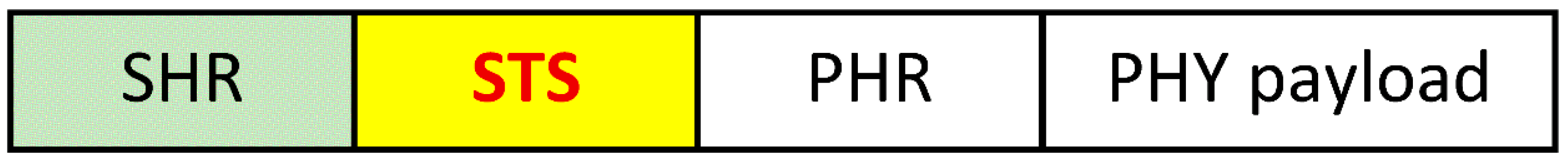
The default PHY frame format proposed by EiR [
29] is depicted in
Figure 3, where SHR is the synchronization header (preamble), STS is the scrambled timestamp sequence, and PHR is the PHY header.
To avoid the inter-pulse interferences, [
30] stipulates that every component
of Ipatov ternary symbol (ITS), or STS, is spread out on a symbol of length
by
; where
is Kronecker delta,
is UWB pulse and
is chip duration. To mitigate the side lobes of correlation, this paper proposes a supplementary spreading by a randomly generated sequence
. The sequence of length
is:
The STS sequence of length
,
s(
t), is generated by taking
, A being the result of AES encryption. The peak pulse repetition frequency (PRF) is 499.2 MHz, the mean PRF is 62.4 MHz, resulting
.
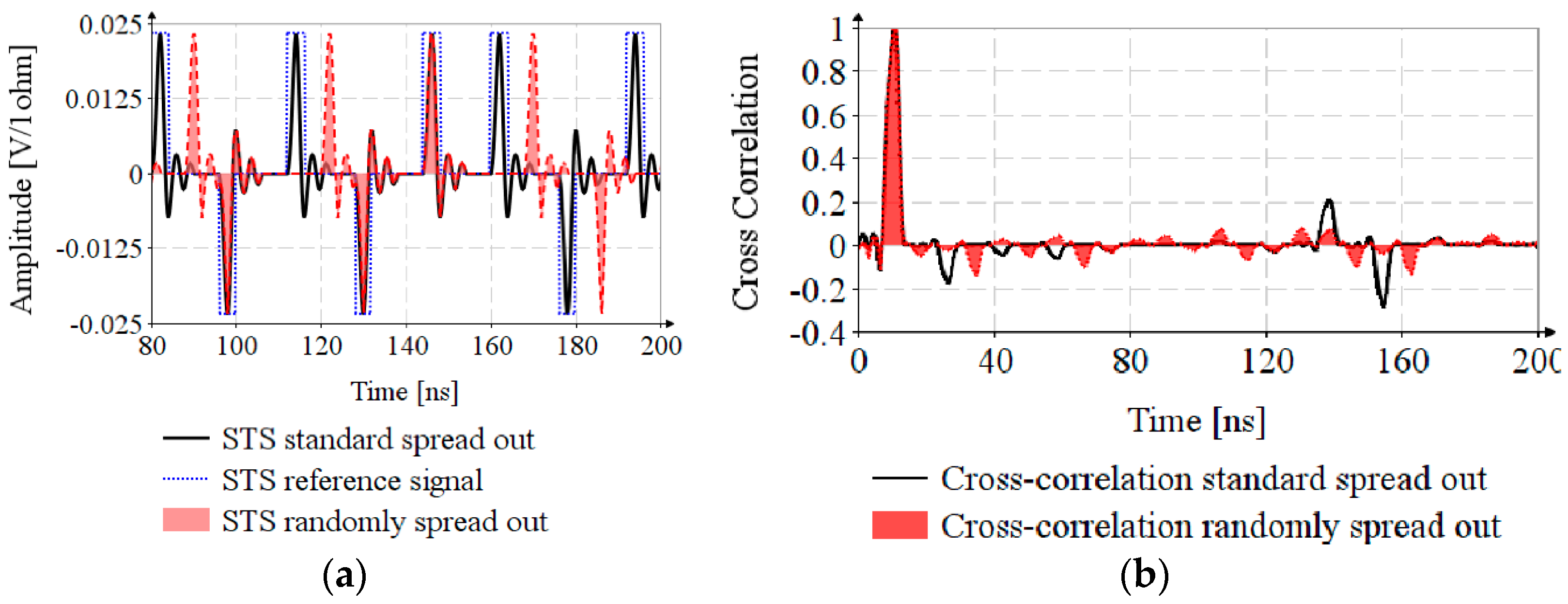
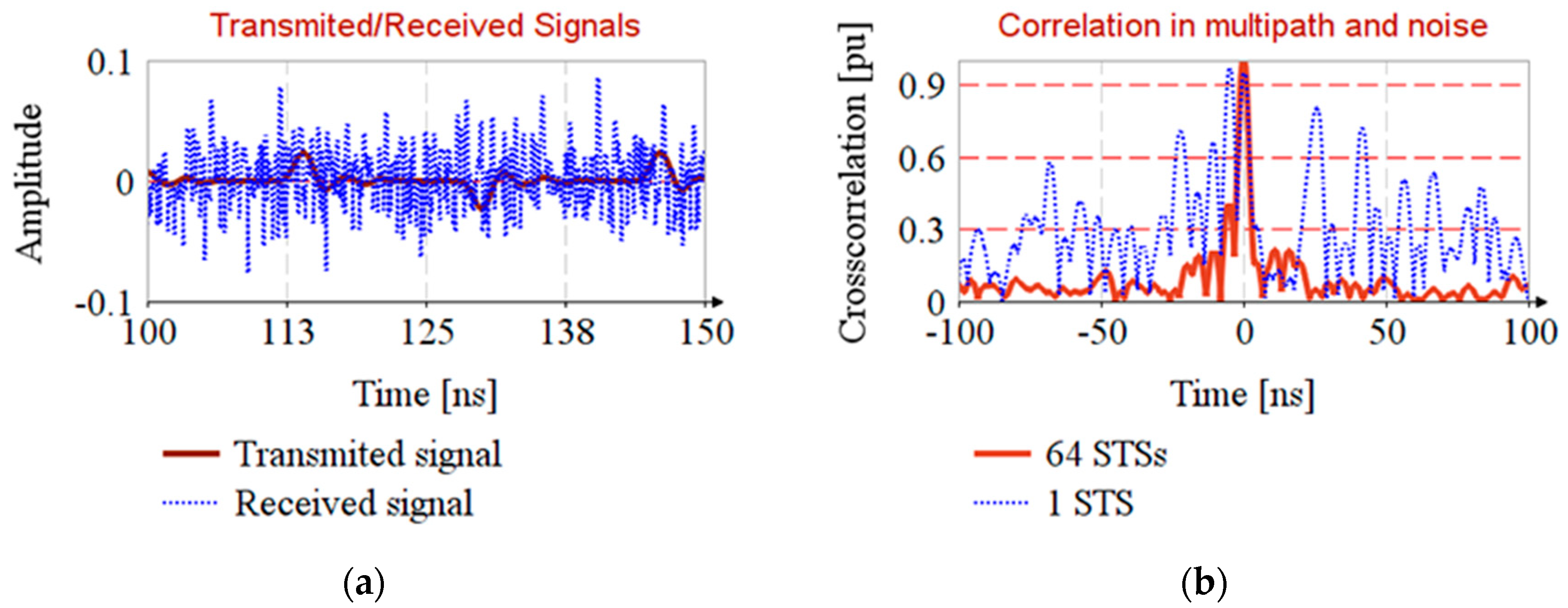
Figure 4a depicts the STS sequences: STS standard spread out is generated according to the standard specifications,
, STS reference signal is the signal needed to achieve correlation and for STS randomly spread out, the
is generated based on a linear feedback shift register with the characteristic polynomial
. The cross-correlation of the reference signal and STSs are shown in
Figure 4b. The ratio between the main lobe and maximum side lobe is
for cross-correlation randomly spread out and
for cross-correlation standard spread out, which proves the efficiency of random spreading.
Figure 4a shows that the random spreading increases the risk of IASI. Therefore, it is necessary to perform the analysis of timestamp estimation for propagation in noisy channel and for multipath propagation.
4.2. Sounding the Channel with Multipath Propagation
The channel sounding is the estimation of the channel impulse response (CIR) using preamble sequence, in order to remove the noise and design the channel equalizer.
The frequency-dependent path gain
is modeled considering an isotropic radiation pattern, with the “antenna attenuation factor” [
31] of ½:
where
are received and transmitted power,
are the transmission and reception antenna gains,
is the path gain at reference distance
,
is the distance between transmitter and receiver,
is the path gain exponent,
is the carrier frequency,
is the frequency and
is the frequency decaying factor.
The frequency decaying factor follows the Friis equation and, in Equation (6), it has the value . The path loss varies from in industrial LOS, in outdoor LOS, to in residential NLOS. It is noted that multipath propagation in the industrial environment leads to an increase in the path gain.
Using the Saleh-Valenzuela statistical model, the propagation paths are designed as the sum of clusters, every cluster having multiple rays. The impulse response
is
where
is the tap weight of
ray in cluster
,
is the ray phase,
is the delay of
cluster and
is the delay of
ray relative to cluster
front. The intervals between the time arrivals of the clusters is modeled as Poisson process with the arrival rate
, and the ray delays inside the cluster are modeled as a mixture of two Poisson processes with arrival rates
and mixing weight
. The mean power of arriving clusters follows an exponential decay with time constant
, having a normal distribution around the mean value
, and the cluster shape also bears to an exponential decay with time constant
.
In the above CIR model, the first path has the highest energy. In non-line-of-sight propagation, there are cases when the first path is strongly attenuated. For such situations, [
31] proposes a new modeling for the first path.
where
describes the attenuation of the first path,
determines how fast the power delay profile (PDP) increases, and
determines the profile decay. By joining Equations (7) and (8), the CIR,
h(
t) can be found.
The preamble sequence consists of a string of 32 or 64 Ipatov ternary symbols, every symbol having 91 elements with 81 non-zero elements [
30]. An Ipatov symbol has “perfect” periodic autocorrelation, i.e., all side lobes of autocorrelation are zero, and using Wiener-Hopf equation, by cross-correlation of the received signal
with the input Ipatov sequence
results immediately the CIR,
where autocorrelation of ITS is:
.
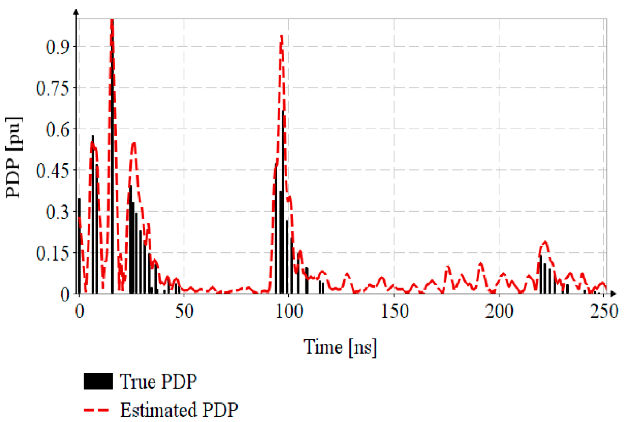
For outdoor, NLOS and multipath propagation environment, the channel PDP,
is modeled based on Equations (7) and (8), with the parameters retrieved from [
31], and synthesized in
Table 2.
For channel sounding, the EiR standard specifies a mandatory preamble sequence of 32 or 64 ITSs, the Ipatov symbol having a number of 91 elements with 10 zero elements. In this paper, the CIR is estimated only using one ITS with a total of 57 elements including 8 zero elements [
32]. The transmitted sequence of pulses,
, is generated based on Equation (5), with
, where
is the
kth element of ITS. The received signal
is the convolution of PDP with the emitted sequence. The CIR estimation,
, is achieved by the cross-correlation of the received signal
with the Ipatov symbol
.
Figure 5 shows that the CIR estimation, estimated PDP, is close enough to the true PDP. By successive transmission of ITSs contained in the preamble, the estimations are accumulated and averaged, resulting in SNR reduction and CIR estimation improvement.
This CIR estimate will be used in the following paragraphs, for analysis of timestamp estimation in channels with multipath propagation. This is a classical channel model, more detailed models are being published in the recent research [
33,
34].
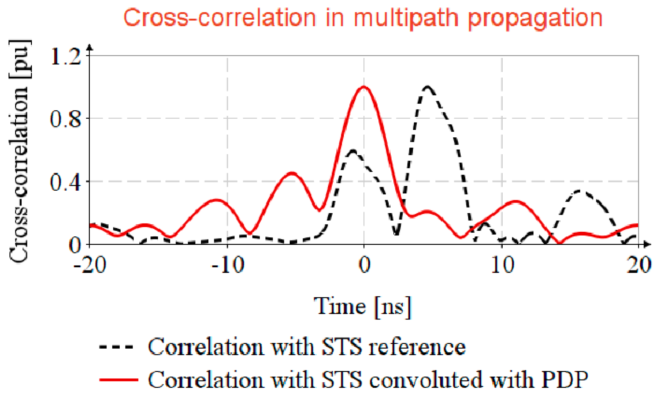
4.3. Timestamp Estimation in Channel with NLOS and Multipath Propagation
The EiR specifies that STS consists of 32, 64, 128 AES-128 sequences, successively transmitted, but in this section only one AES sequence is considered for analysis the impact of multipath propagation.
The STS is generated based on Equation (5) with random spread out, and for propagation simulation it is convoluted with .
In the usual way, the received signal is passed through an equalizer filter and cross-corelated with the STS reference
. In this article, an easier way for timestamp detection is proposed, that is, to generate a virtual propagated STS reference by convolution of the STS reference with the estimated CIR,
, and cross-correlation of received sequence
with locally generated replicas
as depicted in Algorithm 1.
| Algorithm 1: Timestamp estimation in multipath propagation |
| Inputs: STS reference (AES-128 sequence), ; Received STS, |
| 1. Generate locally replica of STS: |
|
|
2. Compute the received sequence: |
|
| 3. Timestamp estimation: |
|
| Output: return
|
Figure 6 shows that by cross-correlating the received STS,
, with the STS reference,
, the timestamp is not detectable, (see the correlation with STS reference trace), and that the cross-correlation of received signal with the locally generated replica,
, the side lobes are strongly attenuated (see the correlation with STS reference convoluted with PDP trace).
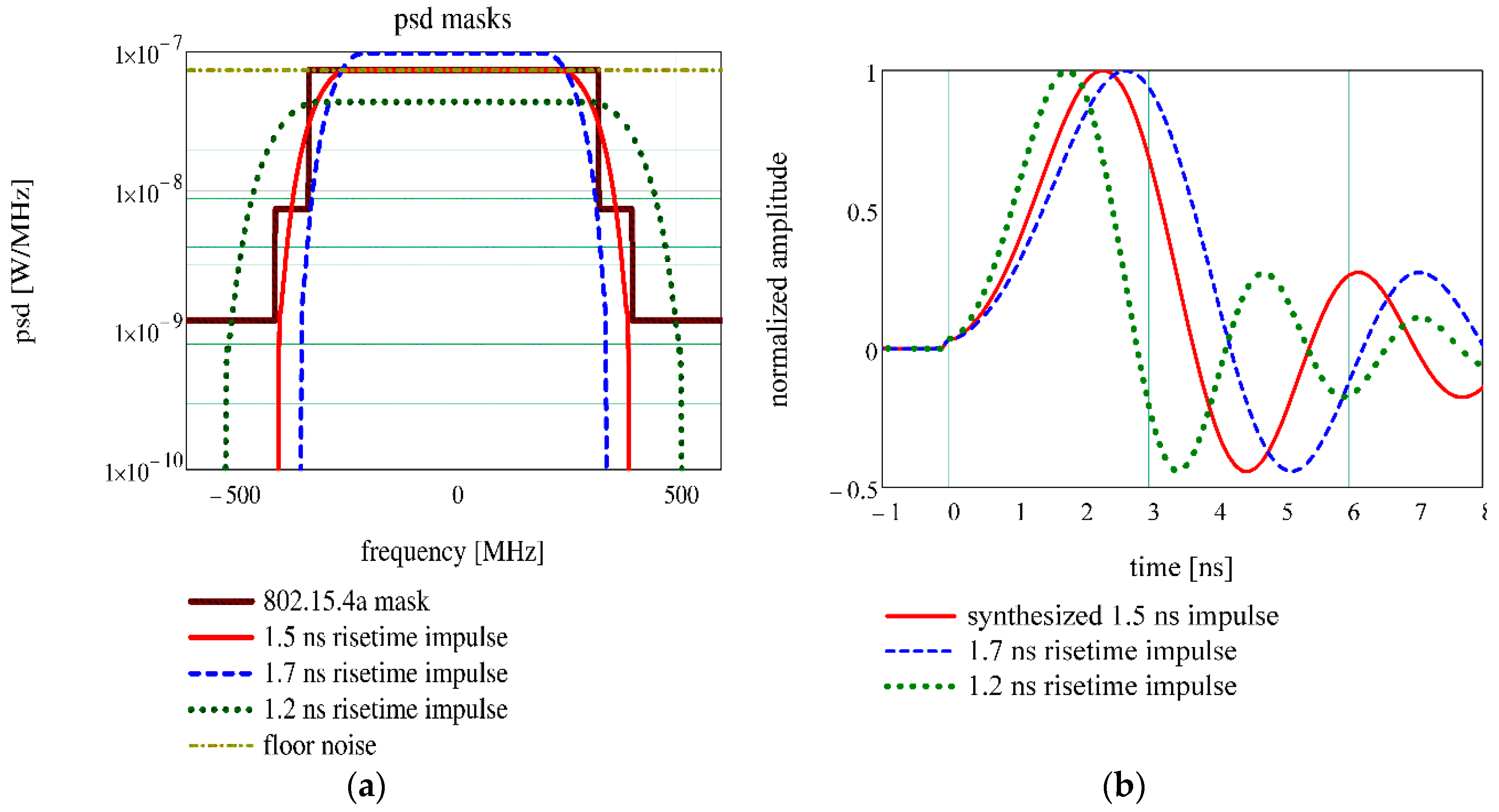
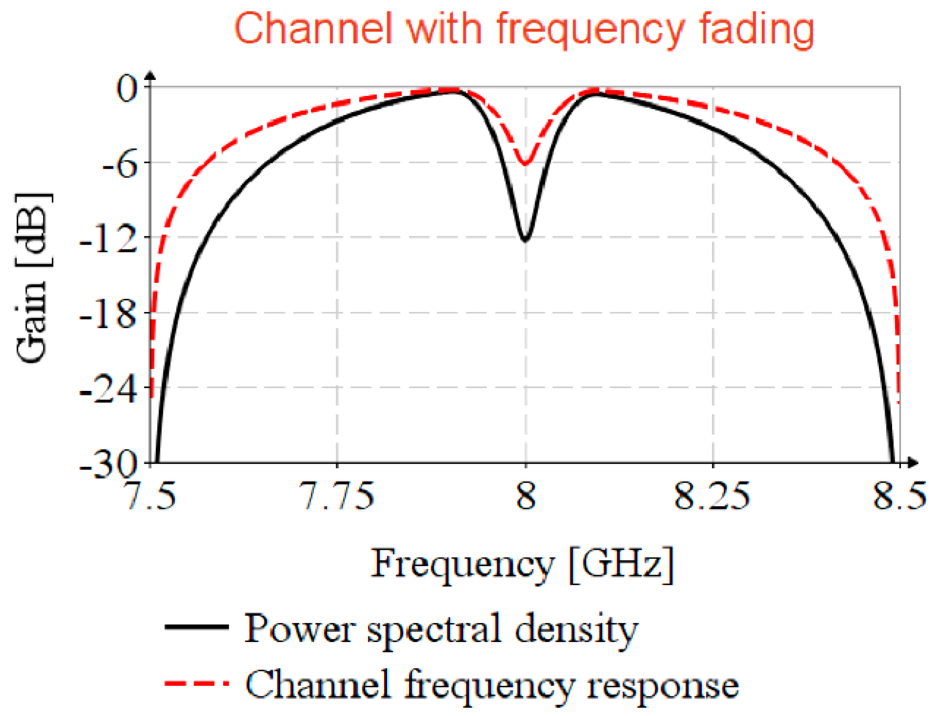
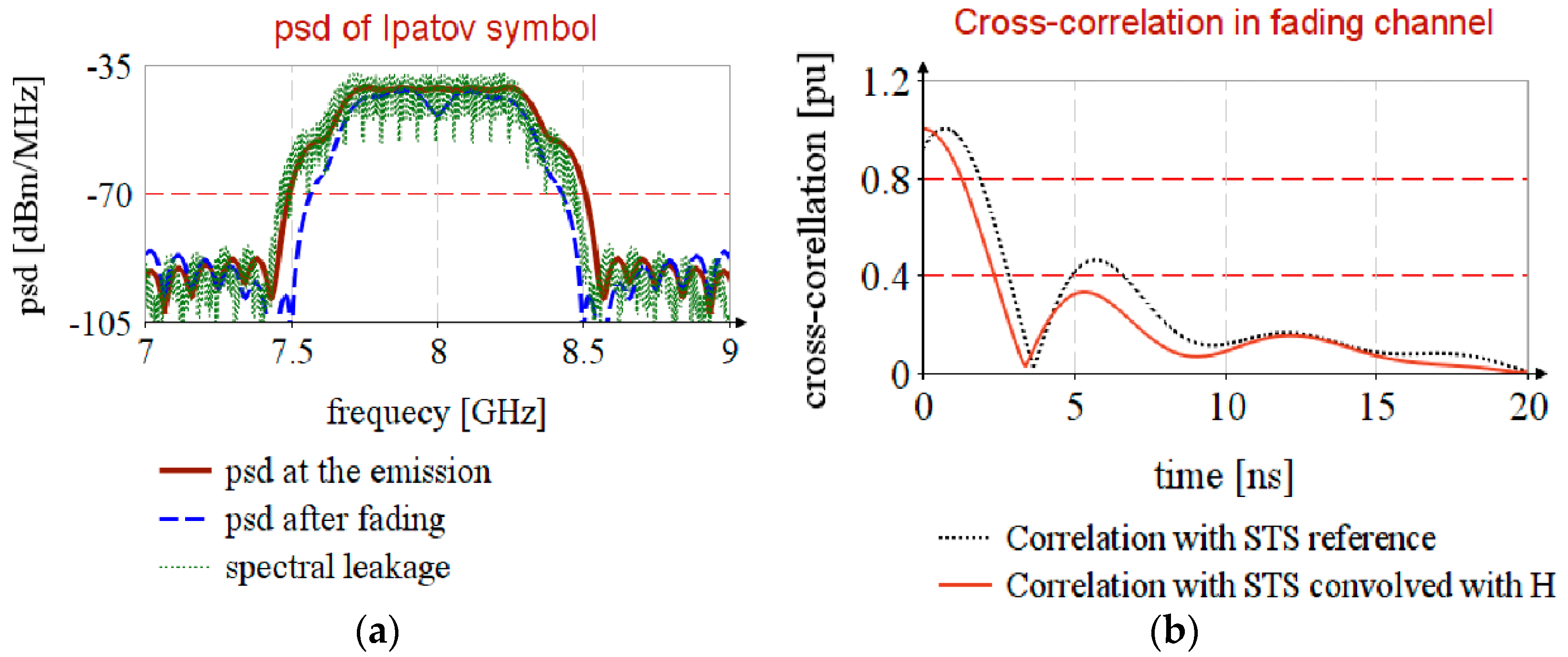
4.5. UWB Channel with Frequency Selective Fading
Depending on antenna design, or antenna position relative to external objects, it is possible to encounter frequency selective fading [
35,
36]. To analyze the impact of frequency fading in timestamp detection, consider UWB channel 9 with the spectral mask profile power spectral density, illustrated in
Figure 8, having a selective fading of
at carrier frequency and frequency decaying factor of
. The channel frequency response,
, is achieved by Kolmogorov factorization (
Appendix A).
To estimate the CIR,
, the Ipatov symbol,
, is shifted on to the carrier,
, by complex modulation with
). The cross-correlation is performed in the frequency domain, and to avoid the circular correlation, the series is padded with zeros. The propagation of STS in the faded channel is simulated by the shifting of the STS on to the carrier and by the convolution with
. The timestamp estimation is detailed in Algorithm 3.
| Algorithm 3: Timestamp estimation in channel with frequency selective fading |
| Inputs: Ipatov symbol, ; STS, |
| CIR estimation: |
| 1. Lift up the Ipatov symbol on the carrier: |
|
| 2. Complete the series with zero and perform FFT. |
|
| 3. Convolve the Ipatov symbol with CIR: |
|
| 4. CIR estimation by cross-correlation: |
|
| Timstamp estimation from STS: |
| 5. Shift STS to carrier, complete with zero and perform FFT: |
|
| 6. Generate locally replica of STS: |
|
| 7. Simulate the received STS by convolution: |
|
| 8. Cross-correlation in the frequency domain: |
|
| 9. Correlation in time domain: |
|
| Output: return |
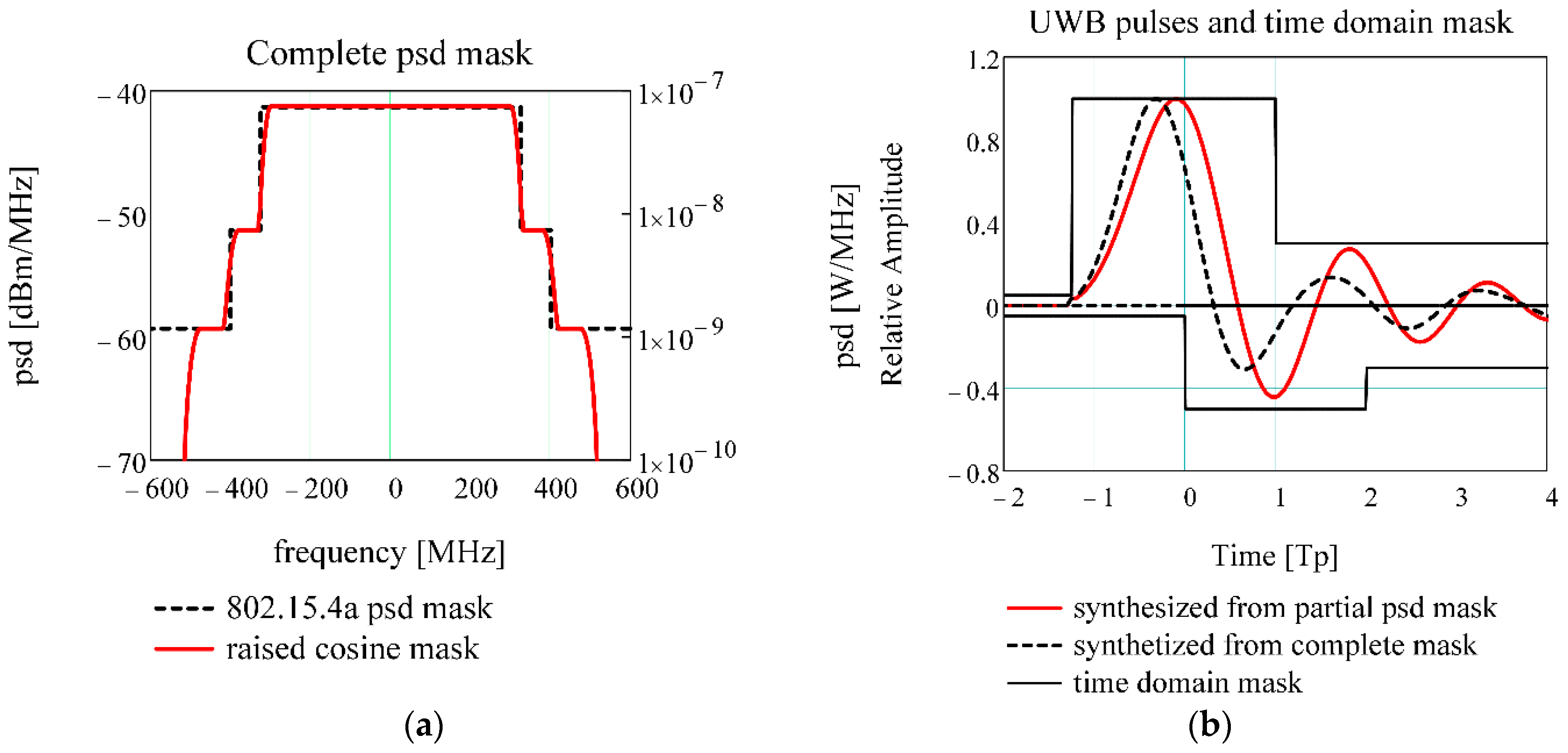
Figure 9a, psd at the emission, shows that Ipatov symbol has a uniform distribution over the entire bandwidth, that it follows the compliant spectral mask (
Figure 2a), and that after propagation, psd after fading, it borrows CIR spectral mask.
The propagation in a channel with frequency fading leads to a small error in timestamp estimation, as shown in
Figure 9b, correlation with STS reference, and this error is cancelled if the received STS is correlated with the locally generated replica, correlation with STS convolved with H.
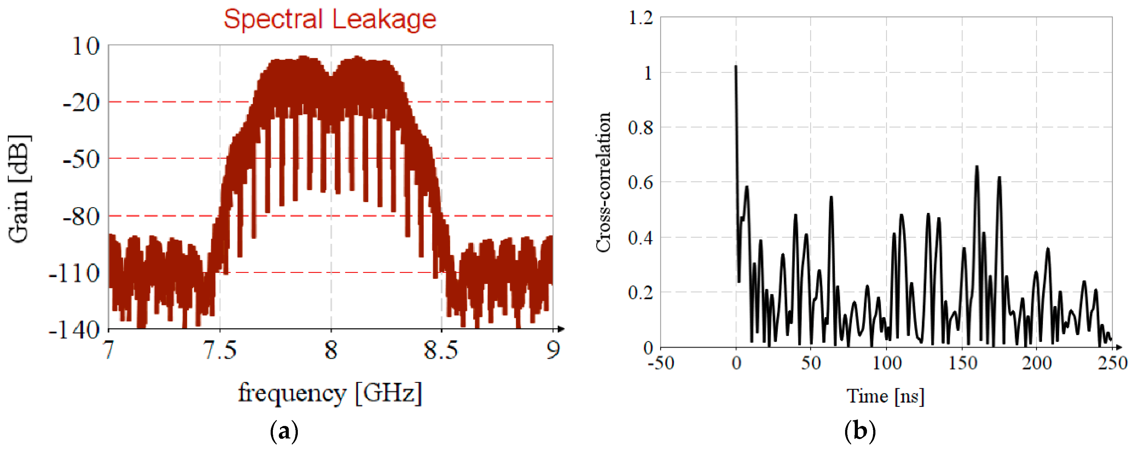
It should be highlighted that the spectral leakage in the FFT leads to the introduction of nonuniformity in the estimated CIR spectrum,
Figure 10a, resulting in incorrect results regarding timestamp estimation,
Figure 10b.


