In this section, we first describe the evacuation scenario used in our research. Then, the proposed system architecture and the control logic used to provide optimal indications to pedestrians are presented. To model error in pedestrian positioning, we use a log-normal propagation model introduced in the next subsection. The last two subsections describe the simulation optimization framework and how the simulation optimization experiments were performed, together with the performance metrics used.
2.1. Evacuation Scenario
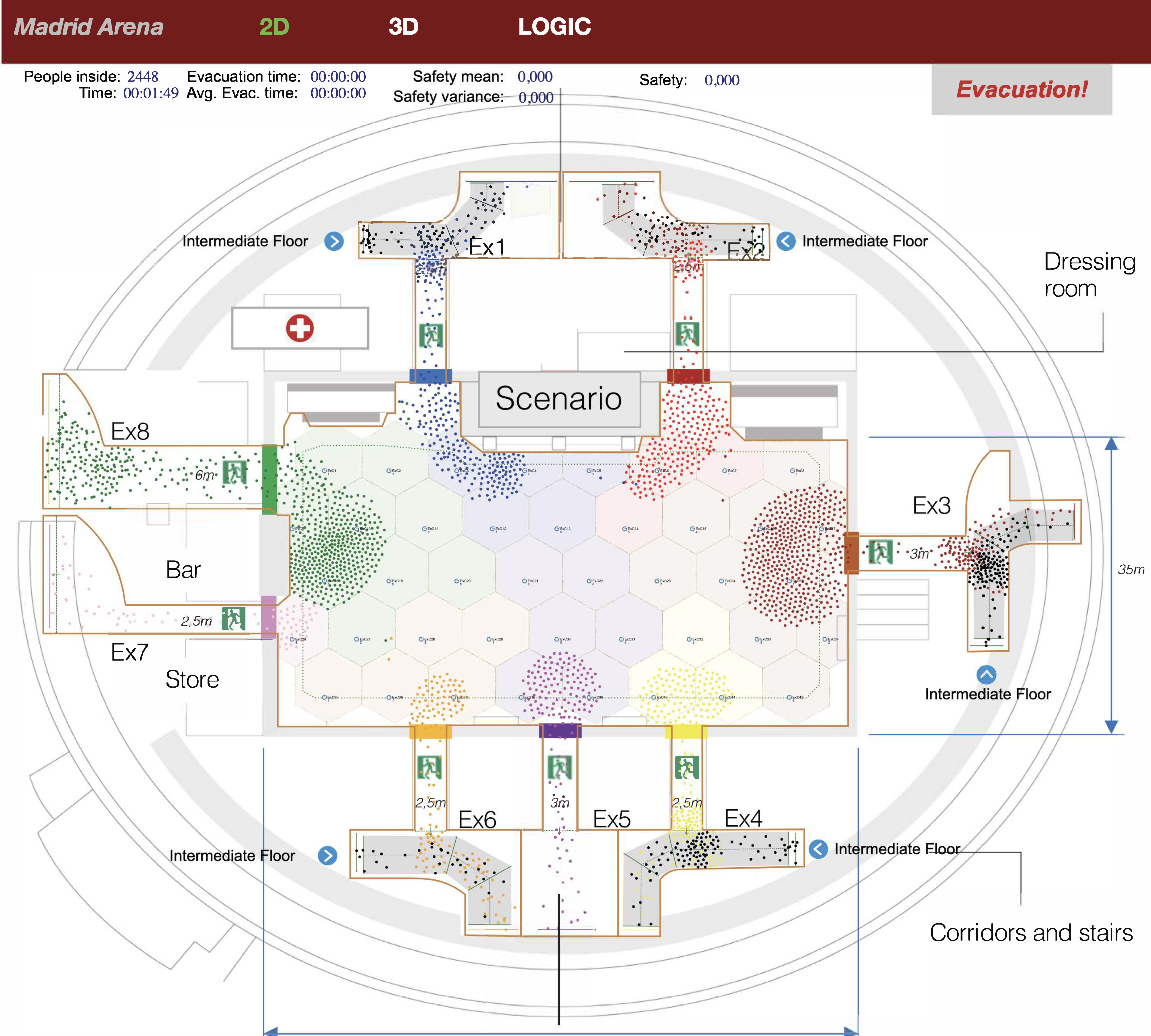
Our evacuation scenario was Madrid Arena, an indoor arena located in Madrid that hosts sports events, commercial, cultural and leisure activities. It has three floors (access, intermediate, and ground) and 30,000 m
2, with a capacity of 10,248 spectators. We studied the evacuation of the ground floor, which has a maximum capacity of 3400 spectators with its retractable bleachers removed.
Figure 1 shows the ground floor layout, with 1925 m
2 and eight exit gates (Ex1 to Ex8) with widths in the range 2.5 m and 6 m. Pedestrian flows from intermediate floors were simulated by injecting pedestrians at exits 1, 2, 3, 4, and 6 at the entry points highlighted with a blue dot.
As in [
23], we divided the ground floor into 42 regular hexagonal cells of 9 m
2 and 6 m width, whose dimensions were chosen to provide a balance between control, wireless coverage, and computational efficiency.In this balance, it must be considered that the number of control actions grows exponentially with the number of cells. If the number of control actions increases, obtaining the control logic’s optimal configuration increases in complexity. Moreover, the number of decision changes induced by the system may be significantly higher. On the other hand, if we make the cells very large, the control actions will be less effective because of the lack of granularity. Finally, 9 sqm is a reasonable size for short-range radio transmissions.
2.2. System Architecture for CellEVAC
We considered using radio-controlled LED wristbands that display colors recommending an exit gate. These LED wristbands (Xylobands (
http://xyloband.com); CrowdLED (
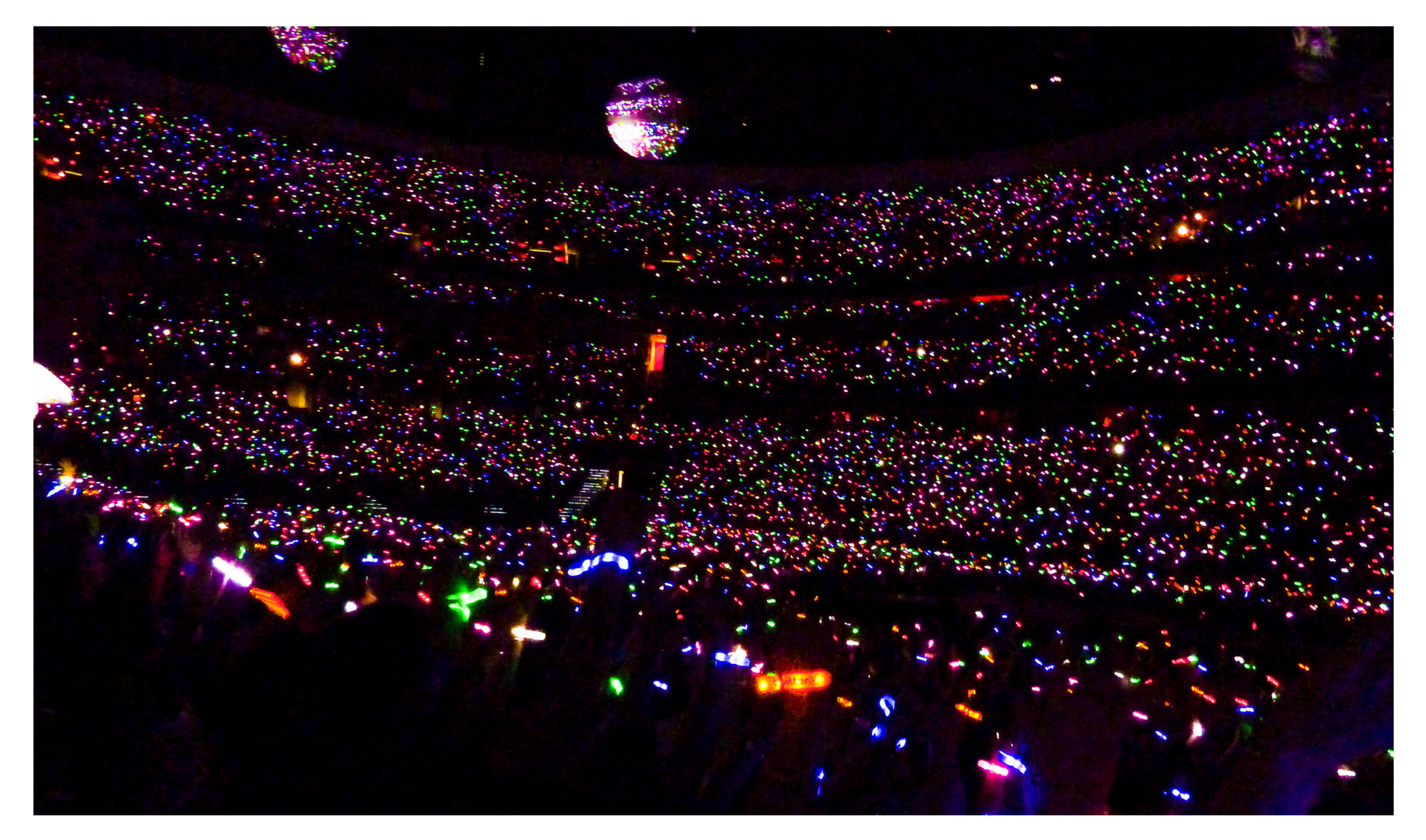
https://crowdled.net)) are widely used at a range of events, from live acts at arenas to product launches, sports matches, parties, and corporate events from 1 to 150,000 people. The wristbands work by creating multiple flash patterns with RGB LEDs that use the full-color spectrum and can be programmed to create visual effects (
Figure 2), with typical illuminance values in the range of 70 to 100 lumens. Usually, radio control has a range of hundreds of meters, and the wristbands have a battery life of approximately 20 h. Two extended features that can be found are the inclusion of RFID tags for registration purposes and zonal control to activate wristbands in separate groups.
Our idea was to extend the functionality of these devices, which is oriented towards creating visual effects, using them in case of emergency to guide people to color-illuminated exit gates. The displayed color in the wristband indicates the evacuee the corresponding exit gate. Besides, a synergic effect of using LED wristband lightning is that it may ease image processing for pedestrian flow estimation, which is used in our system to build the control logic.
To make the use of wristbands effective, pedestrians need to know in advance the purpose and functioning of LED wristbands during emergencies. We propose two complementary mechanisms to provide this knowledge. The first mechanism advertises the functionality in the tickets, the online ticket market, and at the facility’s entry points when delivering the LED wristbands to the attendants. Attendants are advised to follow color instructions during an emergency or during the non-emergency evacuation at the end of the event to speed up and favor a comfortable exit from the facility. By extending the functionality of CellEVAC to normal evacuation (the second mechanism), it is expected that the population will progressively get familiar with the system. This approach has another benefit, providing valuable feedback about the system’s performance. Thus, one possible alternative previous to use the system in case of emergencies would limit its use to non-emergency evacuations to perform field studies about its performance.
As described in the introduction section, the proposed system architecture consists of three subsystems:
Monitoring and control logic subsystem (Controller Node), which monitors pedestrian flows using image processing and generates exit-choice indications in the form of color allocation to cells.
Active RFID cell node network whose purpose is to provide positioning information to pedestrians’ LED wristbands.
Radio-controlled LED wristband subsystem, which includes the LED wristbands with color display and radio-frequency (RF) communication capabilities.
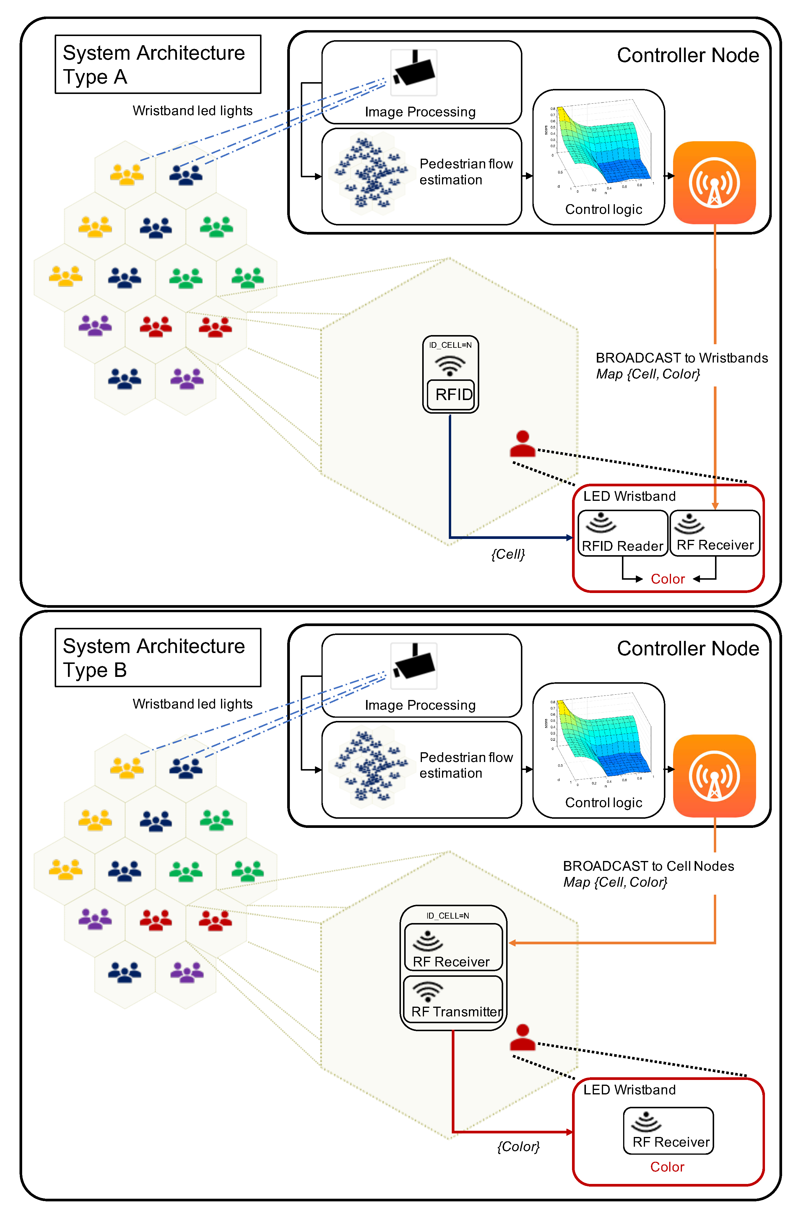
Figure 3 shows two possible implementations of the system architecture (Types A and B) for deploying CellEVAC using existing off-the-shelf technologies. Both alternatives install a controller node with three functional blocks: pedestrian flow estimation based on image processing, control logic based on behavioral optimization [
23], and RF transmitter.
In the controller node, the pedestrian flow estimation block estimates pedestrian density at each cell. This block is assumed to be built on commercially available pedestrian counting technology [
26,
27,
28,
29]. Here, two main candidates emerge to be deployed in real implementations of CellEVAC: Time of Flight People (
https://www.irisys.net/) counting technology, which is based on signal reflection, or Thermal cameras. Both technologies are not affected by lighting conditions and are effective across wide spaces, providing accuracy levels from 95% to 99% (
https://www.trafsys.com/).
Obtained pedestrian densities feed the control logic block that computes the optimal allocation of colors to cell nodes (see
Section 2.3), and the RF transmitter broadcasts messages every five seconds containing the 42 tuples
that assigns a color to each cell. Here, we propose a simple frame format to deliver the messages throughout the RF broadcast communication channel, which can be used in the Type A and B architectures. The frame includes a vector of 42 (cells) * 3 (color bits) = 126 bits, and a header of 16 bits to set the number of cells and color bits. In our scenario, the first byte would be 42 and the second byte 3, stating that each 3 bits sequence corresponds progressively to the color allocated to each cell. The frame ends with trailing bits corresponding to a Cyclic Redundancy Check. Finally, different standard alternatives can be used in the physical layer based on digital modulation such as Frequency-Shift Keying or Phase-Shift Keying. By no means do we mean that this is the only alternative to deliver the messages throughout the broadcast RF channel in the Controller Node, but a realistic and viable alternative.
In the Type A architecture, each cell node is equipped with an active RFID tag [
30] that periodically broadcasts its ID (active RFID beacon [
31]). On the other hand, the wristbands embed an RFID reader that reads the IDs from the surrounding cells. The wristband selects the ID of the message with the highest Received Signal Strength Indicator (RSSI) to estimate the right pedestrian location [
32]. The other element in the wristband is the RF Receiver, which periodically evaluates the broadcast messages with the tuples
from the controller node. By matching the wristband location (selected cell ID) and cell-color tuples, the wristband lights up with the exit gate color assigned to the cell.
In the Type B architecture, the RF Receiver in the cell node receives the broadcast messages from the controller node with the assigned color. Then, the cell node broadcasts the corresponding color message, which is read by the wristbands. As in the Type A architecture, several broadcast messages from different cell-nodes can be received within a window time. Therefore, the same signal strength selection mechanism is used by the wristbands to select the right color.
The most critical part of this architecture is in the positioning functionality. Both RFID and RF communication channels between the cell node network and wristbands have to cope with a complex signal propagation environment. However, the system does not need to obtain exact position coordinates but select the right cell in which the pedestrians are located. It means that a significant lower location resolution is needed and that there is no need to implement triangulation mechanisms based on RSSI [
33]. Another problem to solve is co-channel interference, which may be managed using existing radio resource management schemes [
34]. Besides, the RF transmission channel in the controller node is a one-to-many communication channel that has been used to control commercially available LED wristbands in large events for more than a decade, and do not pose a particular challenge.
A Procedure to Deliver and Retrieve LED Wristbands
In most existing LED wristband systems (e.g., systems used in large music events), organizers deliver wristbands for free at the facility’s entry points that attendants do not have to return. In the Type B architecture, we may take the same approach because the wristbands embed only an RF receiver and a battery, just as in the existing LED wristbands. Currently, the cost of LED wristbands is around 1$ per unit. Thus, the cost of distributing thousands of wristbands is identical to the cost applicable to current systems and affordable by potential business models based on CellEVAC. It would be necessary to add the flow processing module’s cost and the wired sensor network, which would become part of the building’s infrastructure. This type of equipment is available on the market, and it would only be necessary to embed the code developed in this work to implement the control logic.
Note, however, that in the Type A architecture, the wristbands’ hardware architecture is more complex, adding an RFID Reader and a control logic module used to match cell-position and cell-color. It seems reasonable to assume that the LED wristbands’ cost in the Type A architecture doubles the Type B approach’s cost. There is a trade-off between the LED wristbands’ cost and the sensor network infrastructure cost that we believe favors the Type B architecture.
Independently of the cost of the wristbands and the business model, the green economy drives us to define procedures to reuse the wristbands. The critical point here is to incentivize attendants to return the wristbands at the end of the event. We propose to use the Type B architecture in which the wristbands embed the RF Receiver and a passive tag for identification purposes. This hardware architecture is not new, and it is widely used, as we described at the beginning of the subsection. It is worth mentioning that the cost of integrating a passive tag in the wristbands is only a few cents. Our proposal to incentivize wristbands’ return is to implement a registering process at the facility’s entry points. We assume that attendants purchase tickets online using a personal account. At the entry points, the organization staff registers both the ticket QR code and the wristband RFID tag delivered to the attendant. At the end of the event, the organization reads the RFID tags, paired with their corresponding tickets. Finally, the attendant personal account is updated with confirmation information about the return of the wristband. The incentive could be based, for instance, on future ticket purchase discounts.
2.3. Control Logic of CellEVAC
and Pedestrian Behavior
The control logic of CellEVAC is based on a behavioral optimization approach proposed in our previous work in [
23]. Here, we recall the main concepts that build its operation.
Pedestrians’ exit-choice decision modeling based on discrete choice theory [
35] inspired the control logic developed for CellEVAC. Thus, we modeled exit gate color allocation to cell nodes using the simplest and most popular practical discrete choice model, the Multinomial Logit Model (MLM) [
35,
36]. In the MLM control logic, the controller node allocates exit gates (colors) to cells using a probabilistic model, in which the allocation probabilities of exit gate
j to cell-node
c are given by
where
is the set of exit gates, and
is the systematic utility function for cell
c and exit gate
j, which is given by
The attribute is the distance from cell node c to exit gate j, while represents the width of each exit gate. Both attributes are normalized in the range of 0 to 1.
The third attribute is the ratio, which estimates the congestion along a path from cell c to an exit gate j, relative to the least congested path. A group ratio value of 0 indicates that the chosen path is the least congested. When the value of the group ratio tends towards 1, it means that the emptiest path’s imbalance becomes large. The parameter is expected to be positive if it favors pedestrians to follow other pedestrians and is negative otherwise. Note that with this normalization, we assume that the attribute’s relevance is kept constant throughout the evacuation process.
The fourth attribute
accommodates the congestion at exit gates. For a given density value, congestion is higher if the pedestrian flow is low. We reflect this effect through critical density values obtained from the fundamental diagrams of each exit gate (see in [
23]). This
value reflects the density value at which the exit gate’s maximum capacity is reached. Therefore, the
value representing density at exit gate
j is normalized by the corresponding
value. This normalization converts
into a unitless attribute around 1. When the value of
is above 1, it means that exit is highly congested. A value close to 0 would indicate that the exit gate is almost empty. In contrast to the normalization procedure used for the
attribute, the distribution of
values exhibits a decreasing evolution as the number of pedestrians in the evacuation scenario decreases. It seems reasonable to assume that the relevance of congestion at exits as a discriminant factor for exit-choice decreases when the overall number of pedestrians is low, and so
is close to 0 at all exits.
The fifth attribute is the
value associated with cell node
c and exit
j, which captures how the controller is likely to revise the previous exit gate allocation (this attribute was named
in [
23]). We treat this attribute as a binary categorical 0–1 value that equals 1 if the current exit gate of cell
c is
j, and is 0 otherwise (
). Therefore, in a general context, the parameter
is expected to be positive if the controller tends to maintain the previous exit gate allocations, and is negative otherwise. However, we aimed to modulate the tendency to maintain previous decisions, and so
is always positive. As was noted above, we assumed that exit-choice changing evolves as evacuation progresses, and therefore the parameter that modulates
is time-dependent. By observing the pattern of behavior under various simulation settings, it was found reasonable that the tendency to maintain decisions increased linearly depending on the current number of pedestrians:
According to Equation (
3), the parameter
tends to 0 at the beginning of the evacuation, and so the tendency to revise decisions is higher. As the number of pedestrians decreases, the parameter
tends to
, and the tendency is to maintain previous decisions proportionally to the
value.
In the simulation setting used in this work, we used an update cycle of 5 s. We kept this frequency constant and controlled the frequency of the changes at optimal levels using the parameter .
Pedestrian Behavior
In this work, we restrict ourselves to pedestrians that either strictly follow or do not follow the indications provided by CellEVAC during an evacuation. When pedestrians follow the indications, their movement is controlled by the Social Force Model (SFM) [
37] that implements the simulator (see
Section 2.5), and the exit gate indication provided by CellEVAC through the MLM model described above, whose optimal parameter configuration is shown in
Table 1. This configuration under the assumption of perfect pedestrian positioning can be easily obtained through simulation optimization [
23].
If pedestrians do not follow the indications, their movement is controlled in the simulator by the SFM, and the selected exit provided by their individual MLM model (different from the model used by CellEVAC). In this case, we use the configuration of parameters of the MLM model defined in [
23] that simulates standard pedestrian behavior (see
Table 1).
In both scenarios, once a pedestrian selects an exit, pedestrian movement and the path to follow will depend on the destination and the Social Force Model, based on the attractive and repulsive forces existing in the environment at each simulation step. Thus, when using SFM the path that agents follow automatically emerges depending on the environment conditions.
In both models, the group phenomena are captured by the
parameter. However, we do not claim the model is comprehensive, but a reasonable model to capture crowd evacuation movement with parameters currently used in the relevant literature [
21,
35]. Suppose we wanted to perform a detailed evaluation of hybrid behavior in which a pedestrian may follow or not the indications depending on the environmental conditions in real-time. In that case, the MLM model could be easily extended by adding to the systematic utility function a term
in which
is the indication provided by CellEVAC regarding exit gate
j. This way, in the exit-choice decisions, pedestrians would consider together the distance, width, group, congestion, decision-changing inertia, and recommendations provided by CellEVAC at the same time.
2.4. Modeling Positioning
Uncertainty
Active RFID systems are defined by three parts, a reader (wristband), antennas, and a tag (cell node), with their power source. In active RFID applications, RSSI can be used for determining the location of a tag, such that each tag’s RSSI value is proportional to the distance. In our system, the cell-node embeds an active beacon tag that sends out its ID every 3–5 s. Thus, each tag’s RSSI value is proportional to the distance between the wristband and cell node. However, the RSSI value in active RFID applications can be affected by multipath and signal collision [
33].
In free space, the relationship of the power transmitted from cell node to wristbands, assuming the antennas are isotropic and have no directivity, is expressed by the free space path loss equation derived from the Friis transmission equation:
where
is the free space path loss in
,
f is the signal frequency in MHz, and
d is the distance in meters from the cell node to the wristband. For converting RSSI values into a distance measurement in indoor environments with random shadowing effects, one of the most common approaches taken is to use the log-normal propagation model [
38,
39]:
where
is the transmitted power in
,
is the received power,
is the path loss for a reference distance
calculated using the free space path loss equation (Equation (
4)) or by field measurements,
is an arbitrary distance,
is the path loss exponent, and
is a gaussian random variable with zero mean and variance
that models the random variation of the RSSI value. The path loss exponent
in indoor environments such as stadiums can reach values in the range of 4 to 7.
User preference or environmental considerations usually prescribe which parameter configuration to use for most applications. In our simulation scenario, we used a frequency of 2.45 GHz, transmission power of 10 W, path loss exponent
, and reference distance
m. Thus, RSSI can be expressed as
Modifying the variance of the gaussian distribution we may modulate positioning uncertainty.
The procedure to calculate each pedestrian’s location in evacuation simulations is a two-step process that repeats every five seconds:
Given the set of cell nodes
obtain the set of distances
from pedestrian to each cell node
, and calculate the corresponding set {
using Equation (
6).
If there exists a distance value in set such that m, the pedestrian location is . Otherwise, the pedestrian location corresponds to the cell with the maximum value.
2.5. Microscopic Simulation-Optimization Framework
Much of the related work on crowd evacuations rely on detailed simulations. We opted for a multi-agent microscopic simulation framework based on a Social Force Model (SFM) [
37] due to its flexibility and ease of integration of complex interaction and behavior models. Our simulation framework integrates the potential of SFM to mimic physical interactions among evacuees, and of multi-agent systems to simulate complex behaviors and interactions [
40].
In this work, the simulation optimization software framework we developed in [
23] has been extended with the positioning uncertainty model. The software framework embeds agent-based simulation and discrete event simulation, integrating pedestrian behavior modeling, SFM for pedestrian motion, control logic of exit gate indications, positioning, and optimization features.
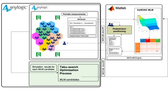
We used the commercially available programming, modeling and simulation software packages AnyLogic
https://www.anylogic.com/ Accessed 18 August 2020 and Matlab
https://www.mathworks.com/ Accessed 19 June 2020. The kernel of the simulation optimization software framework is AnyLogic, which integrates three different modeling methods: discrete event simulation, agent-based simulation, and system dynamics, built on top of a Java-based software development framework. The evacuation scenario layout, pedestrian motion, and evacuation measurements run in AnyLogic, while exit-choice decisions and control logic of exit gate indications are implemented in Matlab. AnyLogic and Matlab are interconnected in a master-slave configuration through the interface with external Java libraries provided by AnyLogic and the Matlab Java API engine (see details below).
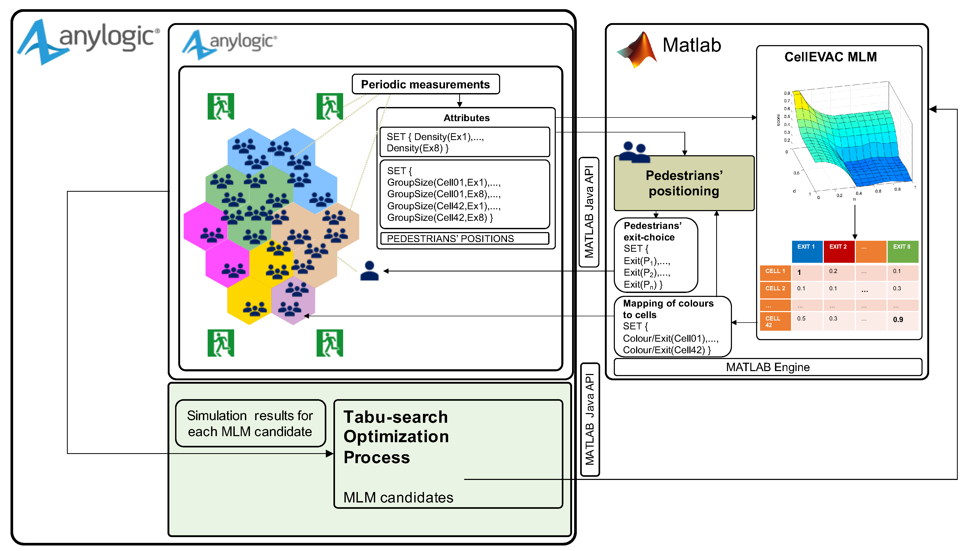
The CellEVAC simulation model with MLM control logic is shown in
Figure 4. The evacuation scenario layout, visualization features, and all the functionality regarding the SFM based pedestrian motion were implemented within AnyLogic.
During a simulation, the first step is to send from AnyLogic to Matlab the set of parameters that configure the CellEVAC MLM and Pedestrians’ positioning modules, including the set of cell node center coordinates and exit gates, and the uncertainty level. Next, the pedestrian positioning and densities at exit gates and cells are periodically measured and then transformed into the set of attributes: pedestrian positions, density at each exit gate, and group of pedestrians along the path to each exit. The group size of each pair cell-exit gate is calculated by adding the pedestrians in the cells that are closer to each exit. All these attributes feed the CellEVAC MLM module in Matlab that implements the decision logic to map colors (exit gates) to cells. This mapping is sent back to AnyLogic for visualization purposes, and to the Pedestrians’ positioning module within Matlab to allocate exit gates (colors) to pedestrians (LED wristbands). The Pedestrians’ positioning module implements the function that locates each pedestrian in a given cell-node using the positioning uncertainty model. The output of the Pedestrians’ positioning module is the set of pairs pedestrian-exit gate, which is sent to AnyLogic for simulating pedestrian motion.
To search for optimal configurations of the MLM model, we used a simulation optimization process that adopts a Tabu-Search algorithm (TS) [
41], which iteratively searches the solution space. At the same time, the microscopic crowd simulation guides the search by evaluating the evacuation time and safety of the solutions generated by the TS algorithm. The optimization process is built on top of the OptQuest
https://www.opttek.com/ Accessed 18 August 2020 optimization engine provided by AnyLogic.
Figure 4 shows the optimization module on a green background. The parameters of the CellEVAC MLM model are the “MLM candidates” generated by the TS algorithm. Thus, each candidate is defined by a tentative set of parameters
sent to the MATLAB Engine at each iteration of the optimization process. The simulations results are sent back to the optimization module for its evaluation and thus guide the optimization process.
2.6. Simulation-Optimization Experiments
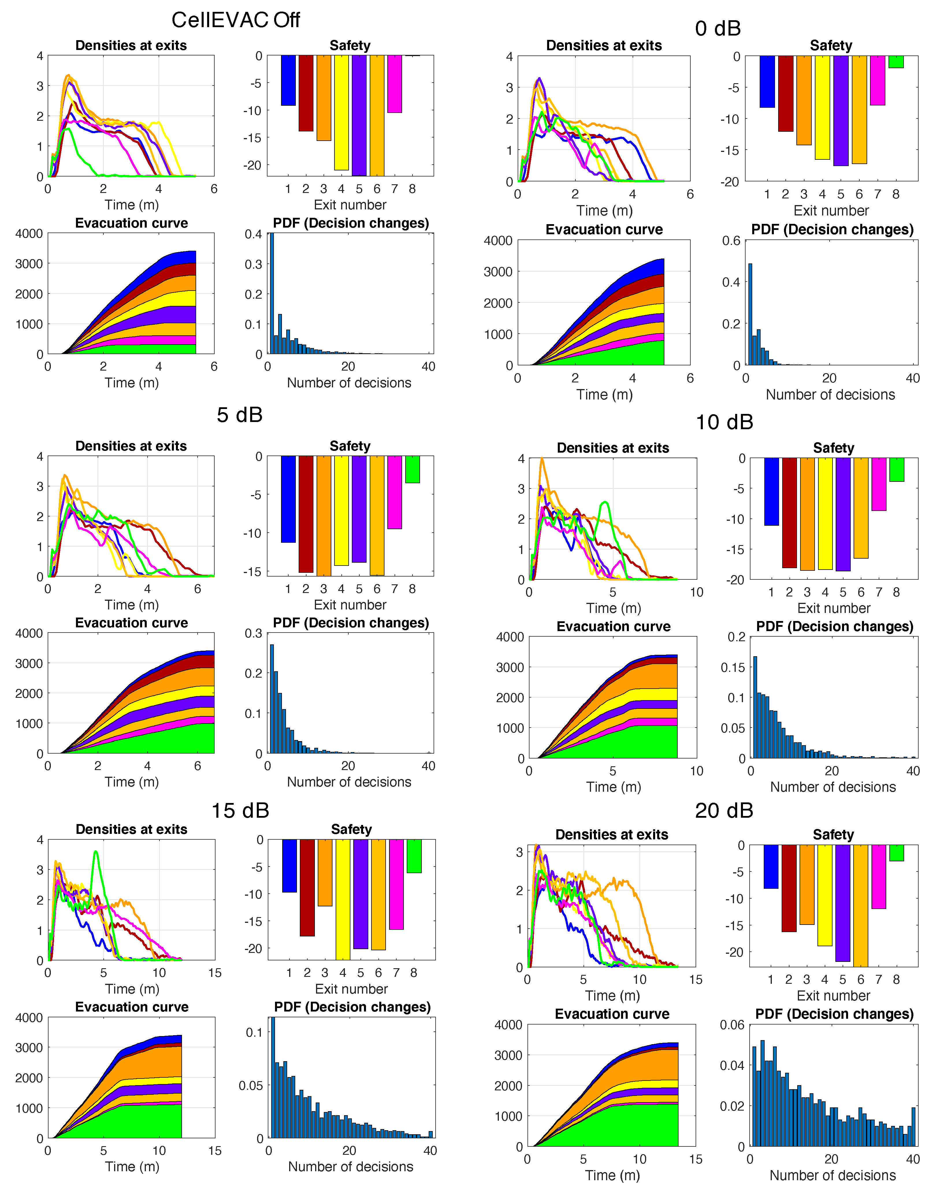
The performance measurements in all the experiments were the total evacuation time, average safety, variance of safety, and the average number of pedestrians’ exit-choice decision changes. The average and variance of safety are based on the safety values computed at the different exit gates. The procedure to calculate exits’ safety values is first to obtain their Fundamental Diagrams (FD) derived through microscopic simulation. This process is described in detail in [
23]. Below, we summarize the process to improve readability.
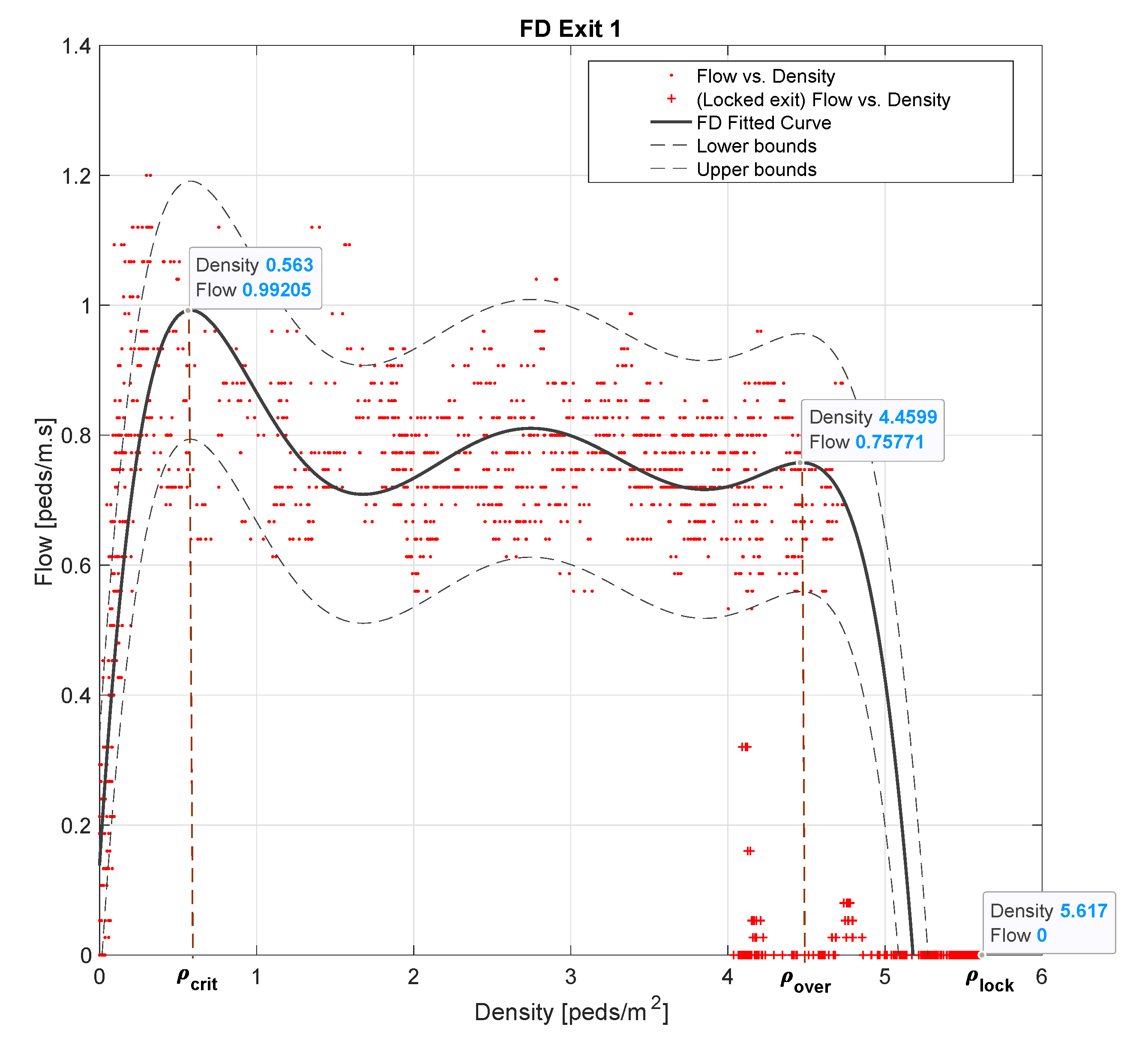
A FD represents the relation between pedestrians’ flow and density. To obtain each FD, we simulate pedestrian flows heading to each exit. Each flow is linearly increased for 10 min to exceeding capacity and then linearly decreased. This sequence is repeated to simulate queue build-up and recuperation phases until a simulation interval of one hour is completed. At minute 50, the exit is locked to characterize pedestrian dynamics in the event of a fall. Density is measured in an area defined by the four closest cells to each exit while we measure pedestrian flow at each exit gate.
Figure 5 illustrates the Fundamental Diagram obtained for Exit 1. We refer to the work in [
23] that shows the FDs for all the exits.
In red points are represented the flow vs. density measurements, while the red crosses show the blocking phase. Using curve fitting, we characterize the different possible phases of pedestrian flow. The critical density delimits the free-flow region. As pedestrian flow increases, a fast backpropagation shockwave is formed that carries the density value to . This stable state maintains as long as the arc formation due to high pressure is present. During the locking phase, the density value increases from to due to queue accumulation.
These density thresholds are used to build the safety metric at each exit gate
j:
such that
with
Given a set of
N density values measured at exit gate
j, Equations (
8) and (
9) give the time-mean density and density time-variation values in Equation (
7), respectively, which are weighted by
. Density time-variation measures the negative impact of variations of pedestrian flow. Both terms are normalized to 1 using the range defined by
and a predefined threshold
. According to the equations, if exit gate
j is locked,
, while in a safe scenario where densities are always below
,
equals 0.
The value given to
is defined as a function of
and
. Since in our study
is used primarily for comparison purposes, as in [
23],
is defined merely as the following weighted-average function,
We make
equal to 5 to strengthen the influence of density time-variations. Finally, the average and variance of the safety values at the exit gates are obtained as follows.
The variance of safety is used to estimate the imbalance of safety between the exit gates.
Using the performance measurements described above, we conducted two types of experiments: (i) sensitivity analysis to positioning uncertainty and (ii) simulation optimization. In all the simulation set-ups, the evacuee population consisted of 3400 pedestrians on the ground floor, who had a preferred evacuation speed obtained from a uniform distribution between 1.24 and 1.48 m/s. To speed up the simulation optimization experiments, we imposed a deadline of 25 min to each evacuation simulation iteration, after which the simulation iteration was aborted.
Two different evacuation scenarios were considered depending on the experiment: evacuations without external flows (NEF) in which no pedestrians were coming from the upper floors, and evacuations with external flows (EF) (i.e., with pedestrians coming from the upper floors) to simulate more complex pedestrian flow interactions. In EF scenarios, three exit gates were chosen at random at each simulation iteration. Two of these exit gates received an incoming pedestrian flow rate of 120 peds/m, while the third exit gate was blocked.
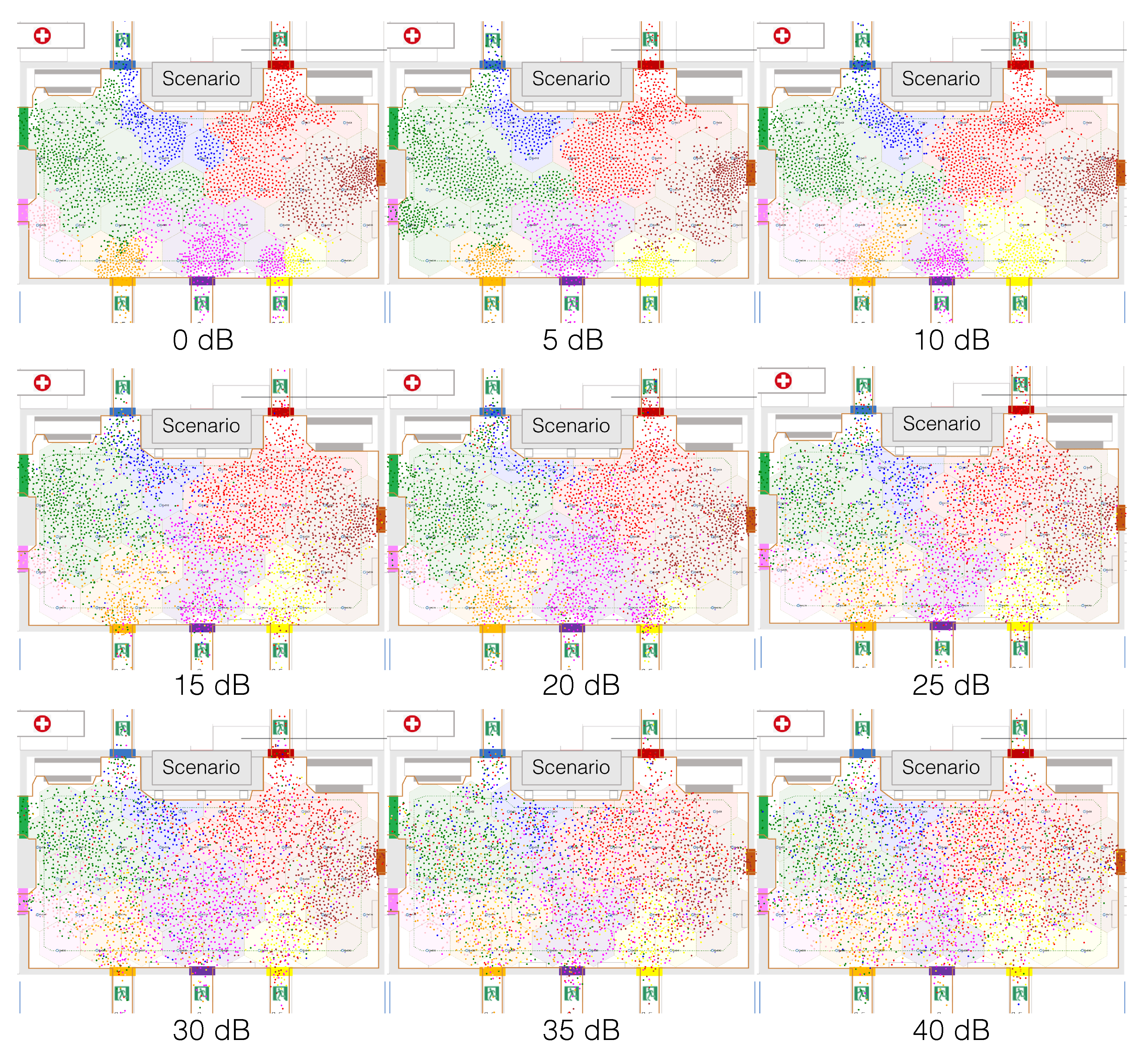
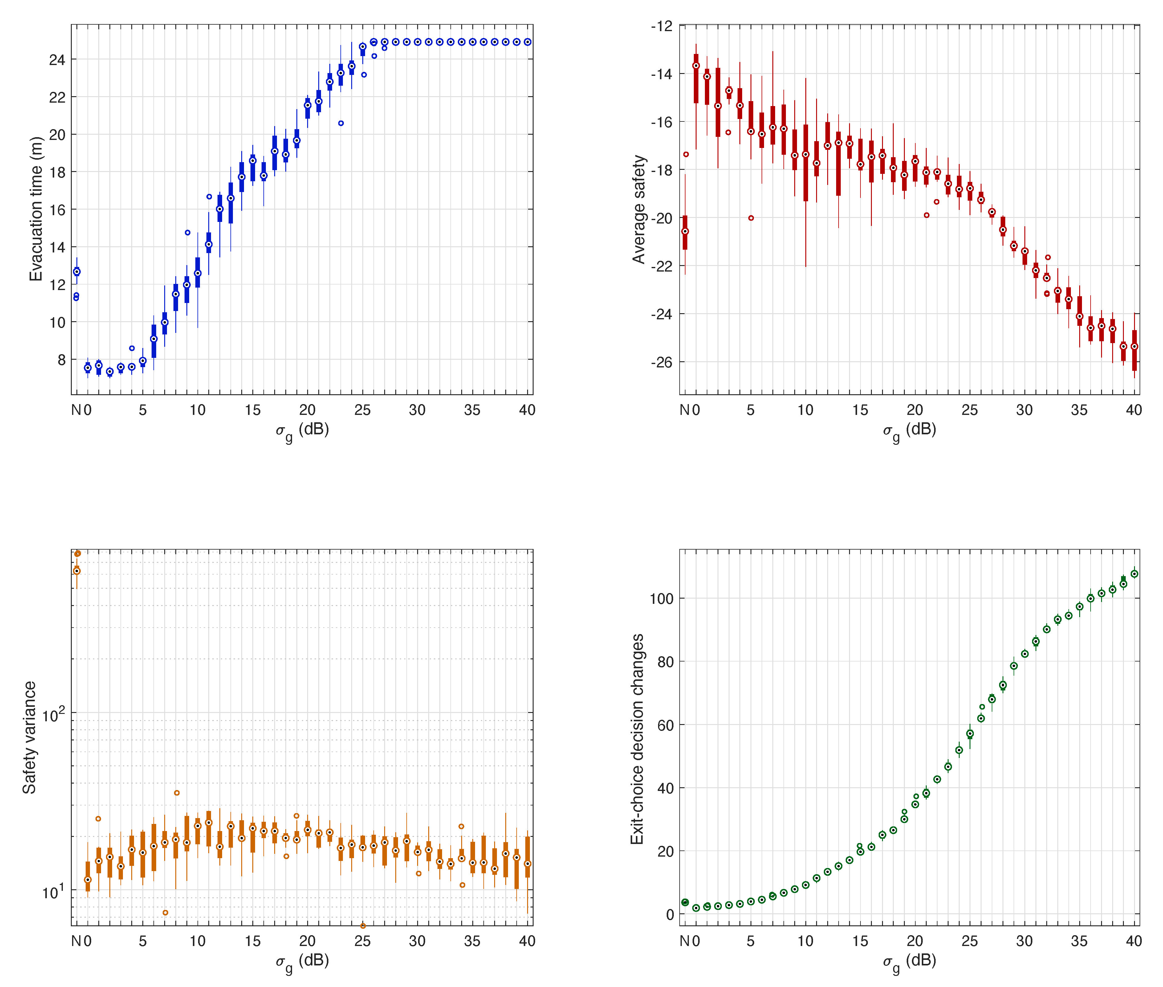
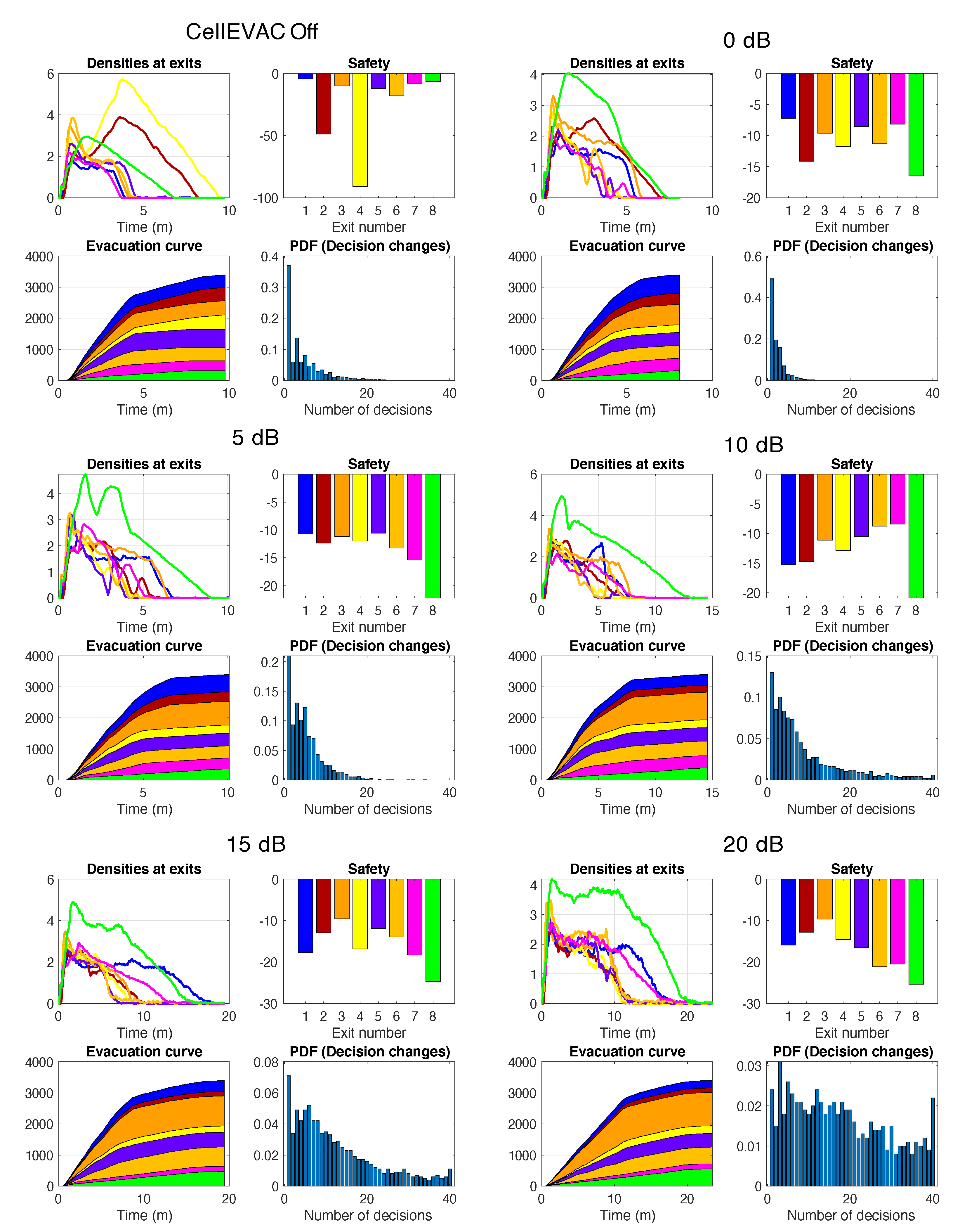
In the sensitivity analysis experiments, each experiment ran the evacuation simulation model multiple times varying the positioning uncertainty level (standard deviation of the Gaussian distribution ) from 0 dB to 40 dB at discrete steps, showing how the simulation output (i.e., the performance measurements) depended on it. To evaluate up to which uncertainty level is beneficial CellEVAC in comparison with not using a guidance system, we also included the case in which pedestrians did not use the CellEVAC system.
Due to the stochastic nature of the evacuation processes, we used a replication algorithm to obtain representative results for a given parameter setting and a specific simulation output. This algorithm defines a minimum and a maximum number of experimental runs per parameter setting (replications of a simulation), a confidence level for the sample mean of replications (simulation output average), and an error percent. The minimum number guarantees the minimum number of replications, while the confidence level and error percent determine if more replications are needed. Simulations for a given parameter configuration stops when the maximum number of replications has been run or when the confidence level is within the given percentage of the mean of the replications to date. In our experimental set-up, evacuation time was used as an output parameter to control the number of replications between 10 and 50. The confidence level was fixed to , and the error percent to .
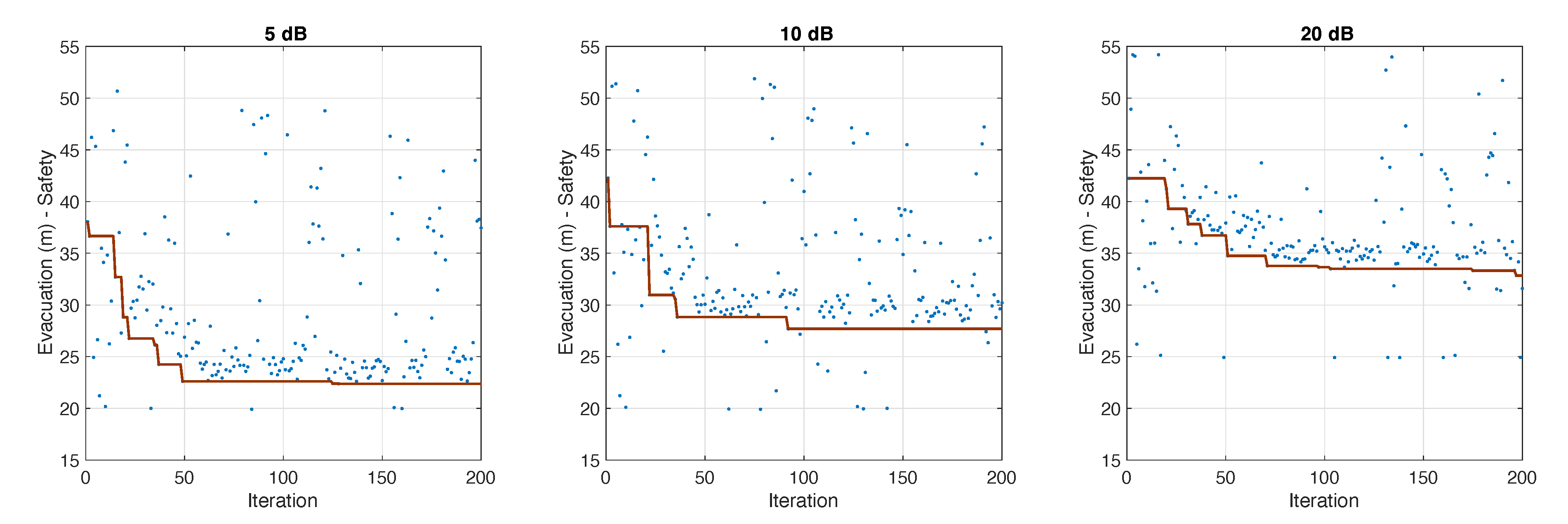
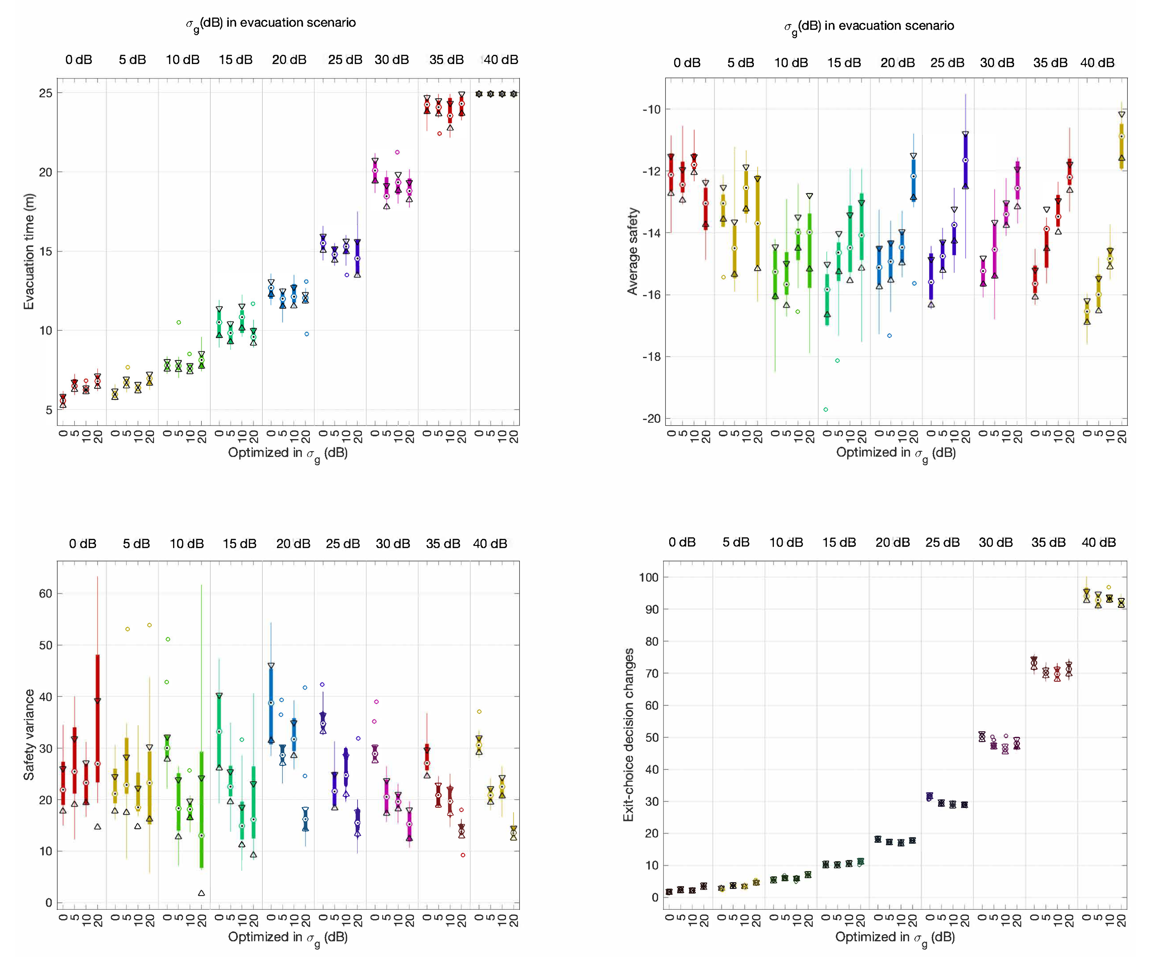
In the simulation optimization experiments, we used the Tabu-search optimization algorithm [
41]. The goal was to find the optimal combination of parameters of the MLM model that resulted in the best possible solution. We considered two different optimization scenarios characterized by the fitness function (objective function) used and the existence of external pedestrian flows.
NEF: Optimize Time and Safety () without External Flows. The goal is to optimize evacuation time and average safety, and the evacuation scenario does not include external pedestrian flows.
EF: Optimize Time and Safety () with External Flows. The goal is to optimize evacuation time and average safety, and the evacuation scenario includes external pedestrian flows.
As in the sensitivity analysis experiments, the optimization algorithm applies a replication algorithm. However, while in the sensitivity analysis, the number of replicas was limited by the evacuation time value, in simulation optimizations, the stop condition was controlled by the fitness function (objective function).


