1. Introduction
The diesel engine has been widely used in construction machinery, agricultural machinery, and transportation field because of its excellent power and fuel economy. The particulate matter (PM) emission cause by diesel engines has a great impact on the human health and environment [
1,
2,
3], and it has an important impact on the generation of haze phenomenon. At present, the main way to remove the particles is to install diesel particulate filter (DPF) on the diesel engine [
4,
5], whose efficiency can reach more than 90%. However, the on-line diagnosis system (OBD) is needed for the reliable monitoring of DPF. With the increasingly strict requirements of OBD emission regulations, the error of traditional differential pressure sensor may exceed the limit value itself [
6]. Therefore, a new type of sensor that can measure the low concentration particulate matter in real time is urgently needed [
7,
8,
9]. At present, the widely used particle sensor is a resistance type particle sensor jointly developed by Bosch Company of Germany and NTK company of Japan. It adopts multilayer ceramic technology to convert the resistance value into the concentration of particles [
10,
11,
12]. However, the real-time concentration of particles cannot be obtained because the resistance value is an accumulation value. Therefore, Almendinger et al. proposed a particle sensor [
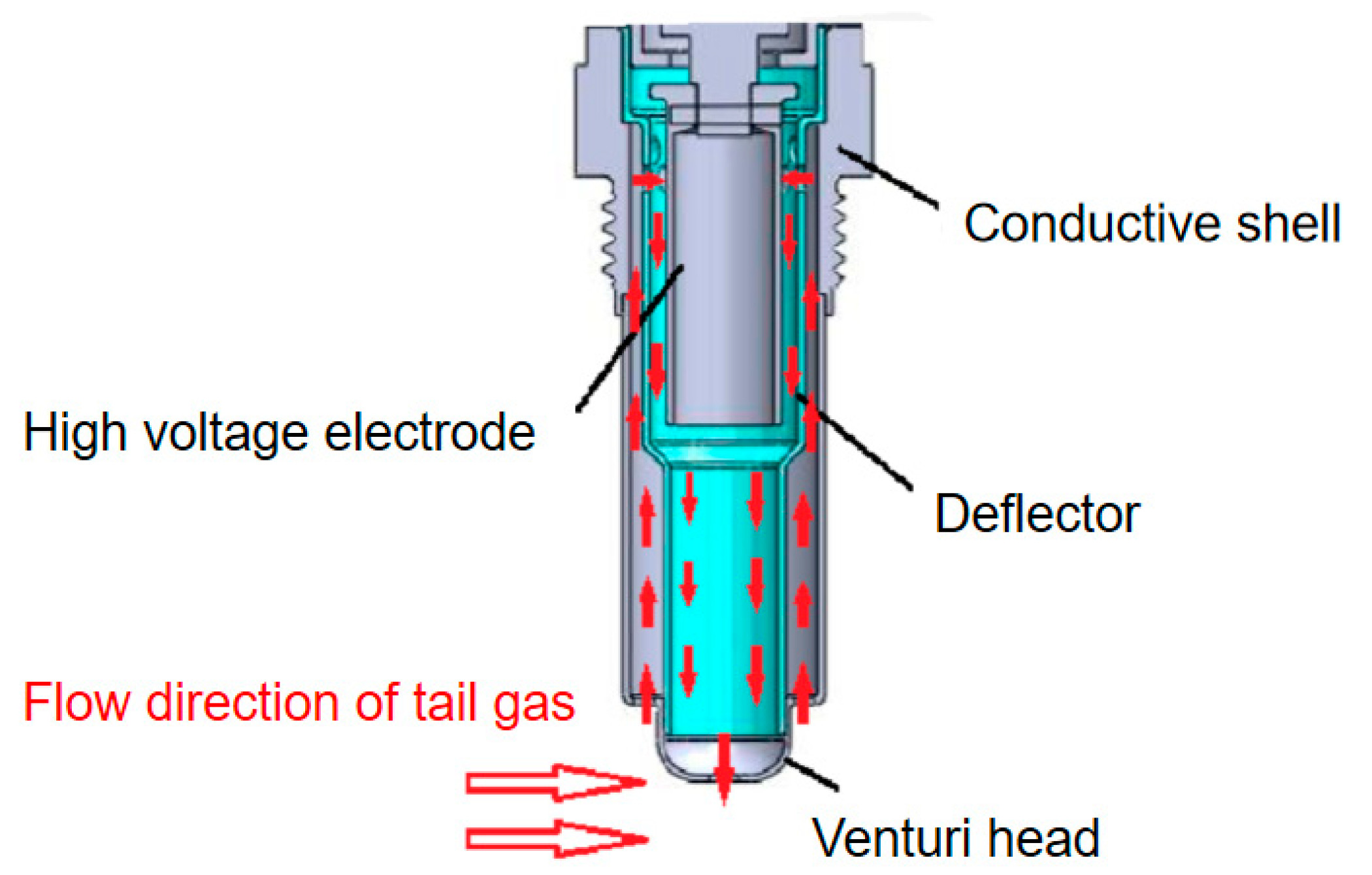
13] for measuring particle concentration and charge loss, as shown in
Figure 1. As the exhaust gas flows through the sensor, there is relatively low air pressure above the leeward side of the sensor inlet, which causes the exhaust gas to flow into the sensor. There is a high voltage electrode on one side of the concentration test range. The particles will be ionized or polarized under the action of high voltage direct current, and move towards the ground electrode under the action of electric field for charge transmission, thus forming a leakage current between the electrode and the conductive shell. The value of the leakage current changes with the change of particle mass concentration in the exhaust gas. The concentration of exhaust particles can be obtained by collecting the leakage current generated by particle movement between electrodes [
14,
15].
Based on the principle of corona discharge, Russell established the principle of electric field charge in 1923, proving that particles are charged by collision with ionized ions. With the deepening of people’s understanding of the charging process of electric neutral objects, the theoretical research results of particle charging have been widely applied to production and life, electrostatic precipitator is the typical application direction of electrostatic field research on the effect of particles.
Domestic and foreign researches have been carried out on the complex environment of internal flow field, temperature field, particle field, electric field, and other fields under the action of multi-phase coupling in the high-temperature dust removal process of a dust collector. Luo et al. found in their study that temperature change would enhance the effect of ion wind in the sensor and increase the turbulence of airflow inside the dust collector. At the same time, the viscosity of the gas would also increase with the increase of temperature, inhibiting the movement of particles and affecting the dust removal efficiency [
16]. Wu Xiaojun simulated and analyzed the electric field, flow field and particle distribution inside the dust collector, studied the charging, movement and deposition rules of particles under the coupling effect of multiple physical fields, and analyzed the influence rules of working voltage, exhaust velocity, particle size, and sensor structural parameters on the dust removal efficiency of the dust collector [
17].
The output signal value of the leakage current particulate matter sensor is mainly based on the charge transmission of particles in the sensor concentration test range. The particle concentration is the main factor affecting the output signal value of the sensor. However, in the actual working environment, parameters such as exhaust flow rate, exhaust temperature and particle shape will have a positive impact on the charge characteristics of particles and the charge transfer between the sensor plates, thus affecting the sensitivity and accuracy of the output signal value of the sensor.
In this paper, through the numerical simulation of the charged characteristics under different environmental conditions, the influence of exhaust flow rate, exhaust temperature, and particle size on the charge of particles in the sensor is analyzed, which provides a theoretical basis for further improving the prototype mechanism of the leakage flow particle sensor.
4. Analysis of the Influencing Factors of the Particle Charging Characteristics
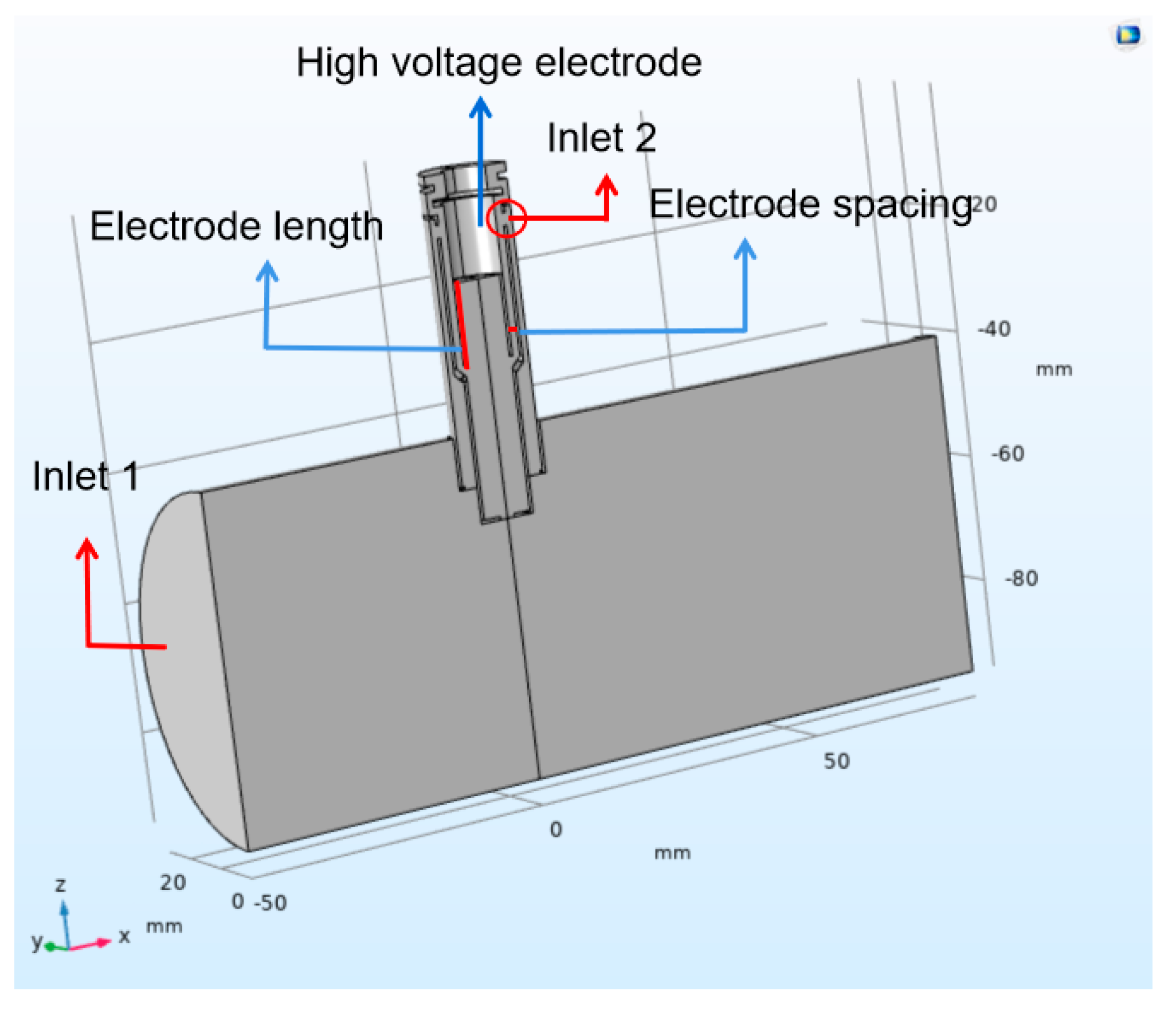
Based on the above-mentioned particle sensor model, the simulation of the charged characteristics of exhaust particulate matter under the coupling effect of multi-physics is conducted. To be specific, environmental temperature, exhaust flow rate, and particle size are focused on to analyze the change rule of particle charge.
4.1. Exhaust Temperature
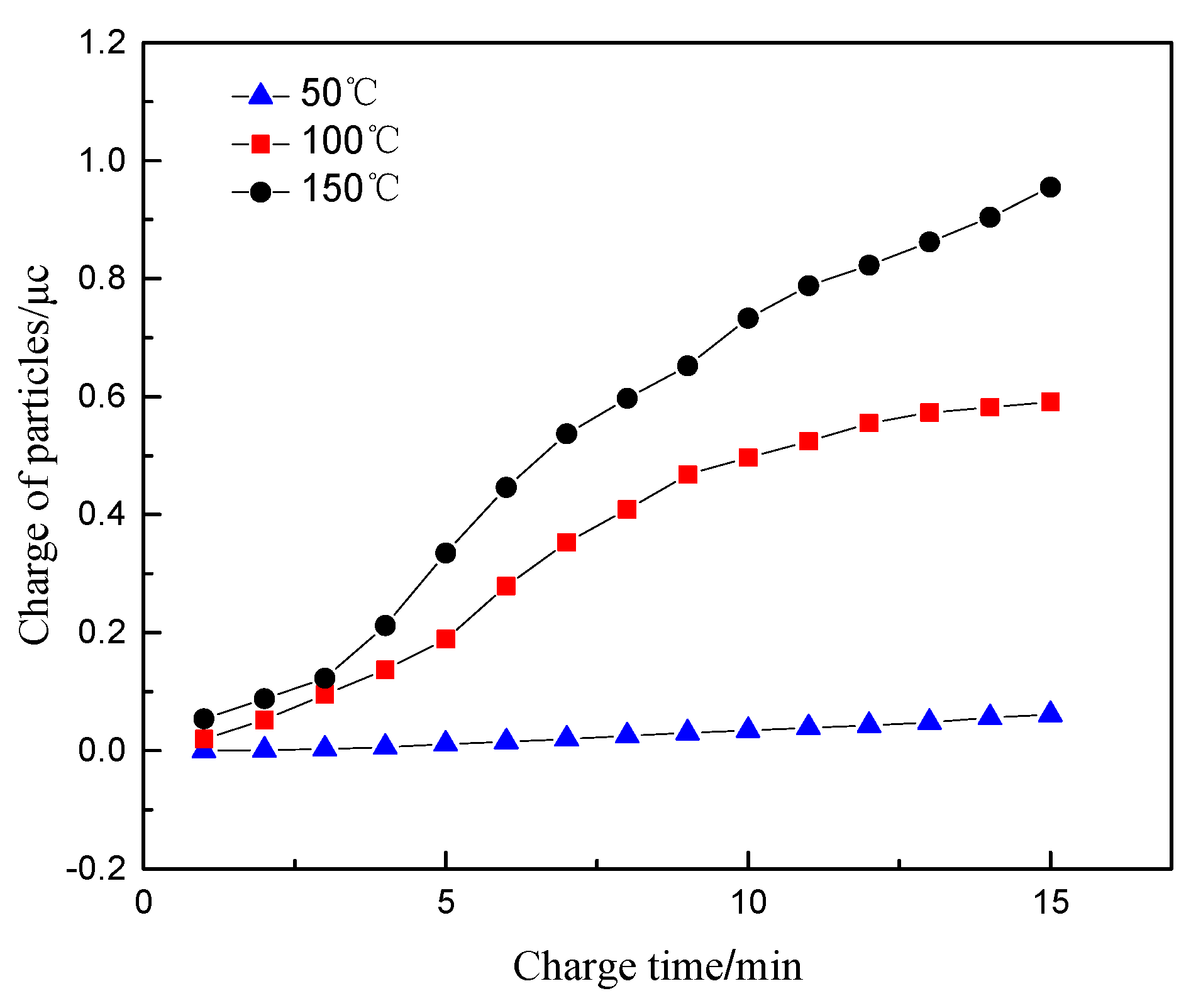
The normal inflow velocity at the inlet 1, the electrode voltage, the concentration of particulate matter and its size are set as 10 m/s, 1000 V, 1.6 mg/m3, and 100 nm. The law of the charge of the particulate matter flowing through the sensor at 50, 100, and 150 °C is studied.
Figure 5 shows the variation of the charge of particulate matter with time at different temperature. It can be seen that at the temperature of 50 °C, the charge of particulate matter does not change significantly with the increase of the charge time. This is because when the temperature is low, the high-voltage electrode does not reach the corona voltage, and thus the corona discharge is insufficient, which leads to the particulates failing to be effectively charged. As the temperature increases, the corona voltage decreases, and the charge of the particles begins to increase significantly with time. At the same time, the charge of the particles increases with temperature. As the temperature increases, the average free path of electrons increases, the number of charged ions generated by collisions between electrons and neutral molecules increases and the frequency and probability of collision with charged ions further increase. As a result, the electric field charge of the particulate matter increases. The increase in temperature further enhances the intensity of the corona discharge, which will further increase the concentration of free electrons and charged ions in the electric field. The irregular thermal movement of the charged ions is affected by the temperature, and the diffuse charge of the particles further increases.
At the same time, the exhaust temperature affects the specific resistance value of carbon particles. When the temperature reaches above 100 °C, the charge transport of the particles mainly conducts through the interior of the particles. The volume specific resistance of the particles is negatively correlated with the temperature. The decrease of the specific resistance value could result in the more frequent move of the charge between the particles, which contributes to an increase in the charge of the particles. Therefore, a higher temperature will lead to an increase in particle charge and charge transfer, further increasing the signal output of the particle sensor.
4.2. Exhaust Gas Flow Rate
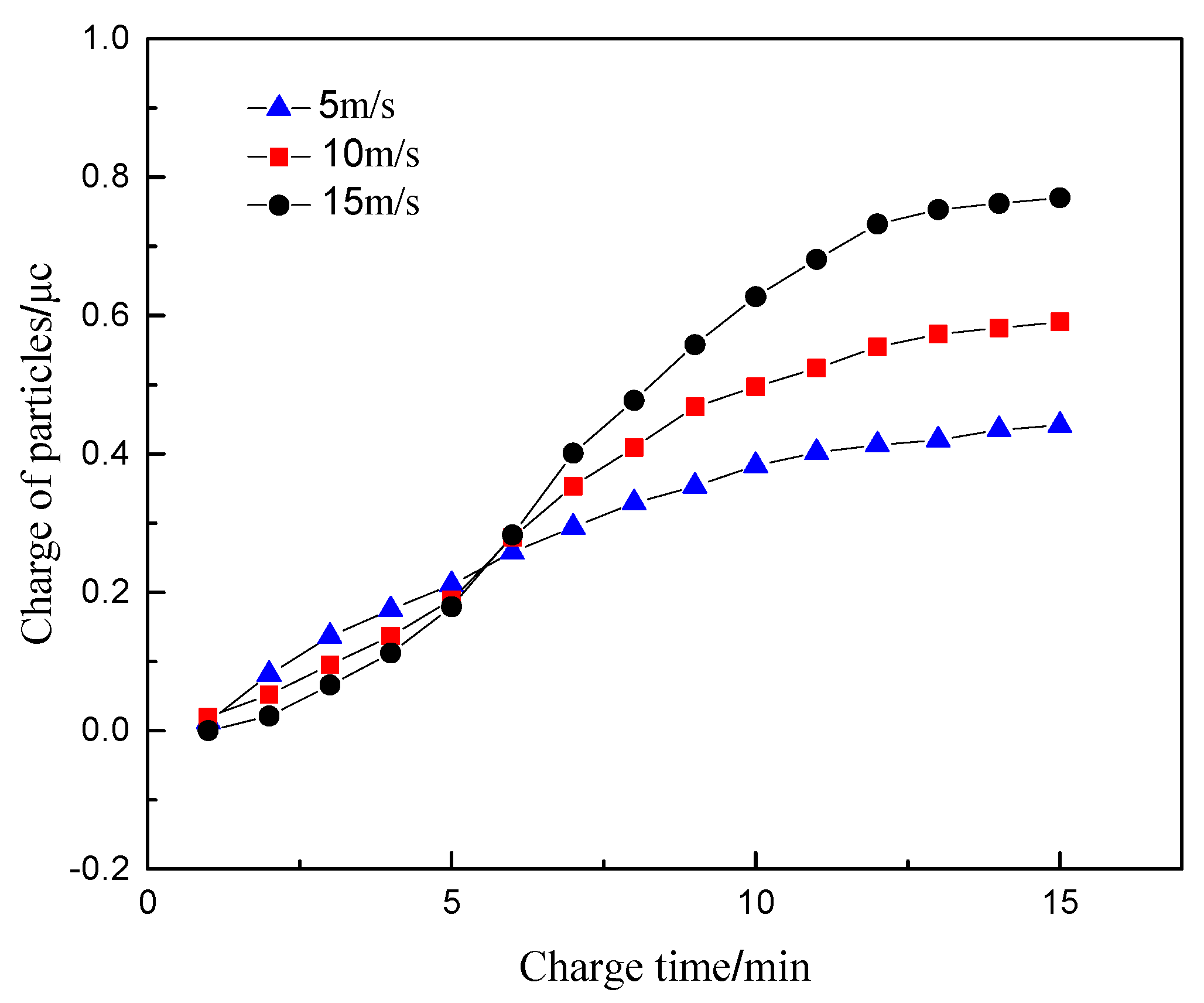
Similarly, the exhaust temperature in the sensor concentration test interval and the electrode voltage are set as 100 °C and 1000 V, respectively. The particle size and the concentration of particulate matter in the sensor are determined as 100 nm and 1.6 mg/m3, respectively. The exhaust gas velocity at the inlet 1 was selected as 5, 10, and 15 m/s. The regularity of the amount of charge of particulate matter flowing through the sensor with time is analyzed.
Figure 6 shows the variation of the charge of particulate matter with time at different flow rates. It can be seen that within the first 6 min before charging, the higher exhaust flow rate brings about the smaller charge of particulate matter. This is because particles are mainly affected by the fluid drag force in the sensor, where their movement speed is mainly related to the fluid speed. The movement speed of the particulate matter also increases with the increase of the exhaust flow rate, which results in the reduction of the residence time of the particulate matter between the sensor plates. In other words, the charging time is reduced. Since the diffusion charge of particulate matter is mainly affected by the residence time of particulate matter in the electric field, the charge amount per unit of particulate matter shows a downward trend. When the charging time exceeds 6 min, the charge amount of the particulate matter increases with the increase of the exhaust flow rate. This is due to the increase of the amount of particulate matter flowing through the sensor concentration test interval in the same period. Therefore, with the increase of the charging time, the charge of the particulate matter generally increases with the increase of the exhaust flow rate, whose variation magnitude is not obvious.
4.3. Particle Size
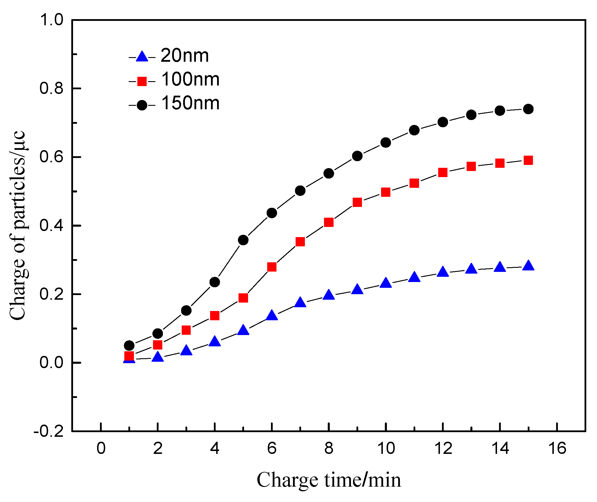
The particle size of diesel exhaust particles is affected by the multiple effects of fuel combustion, particle oxidation and collision. The particle size varies with working conditions, which affects the charging characteristics of the particles. The exhaust temperature in the sensor concentration test zone, the electrode voltage, the concentration of particulate matter in the sensor, and the inlet method phase velocity are set as 100 °C, 1000 V, 1.6 mg/m3, and 10 m/s. The studied particle size parameters are selected as 20, 100, and 150 nm.
Figure 7 shows the variation of the charge of particles with different particle sizes with time. For particles flowing through the sensor concentration test interval, the charge of the particles increases with the increase of the particle size, showing a significant positive correlation. It can be seen from Equation (9) that when the particle size is less than 0.2 μm, the charging effect is mainly in the way of diffusion charging [
16,
24], which is not affected by the electric field charging effect. The particle size dp is proportional to the particle size. At the same time, the particles with the large size possesses the large surface area, which directly strengthens the ability to adsorb charged ions and cause a significant increase in the amount of charge.
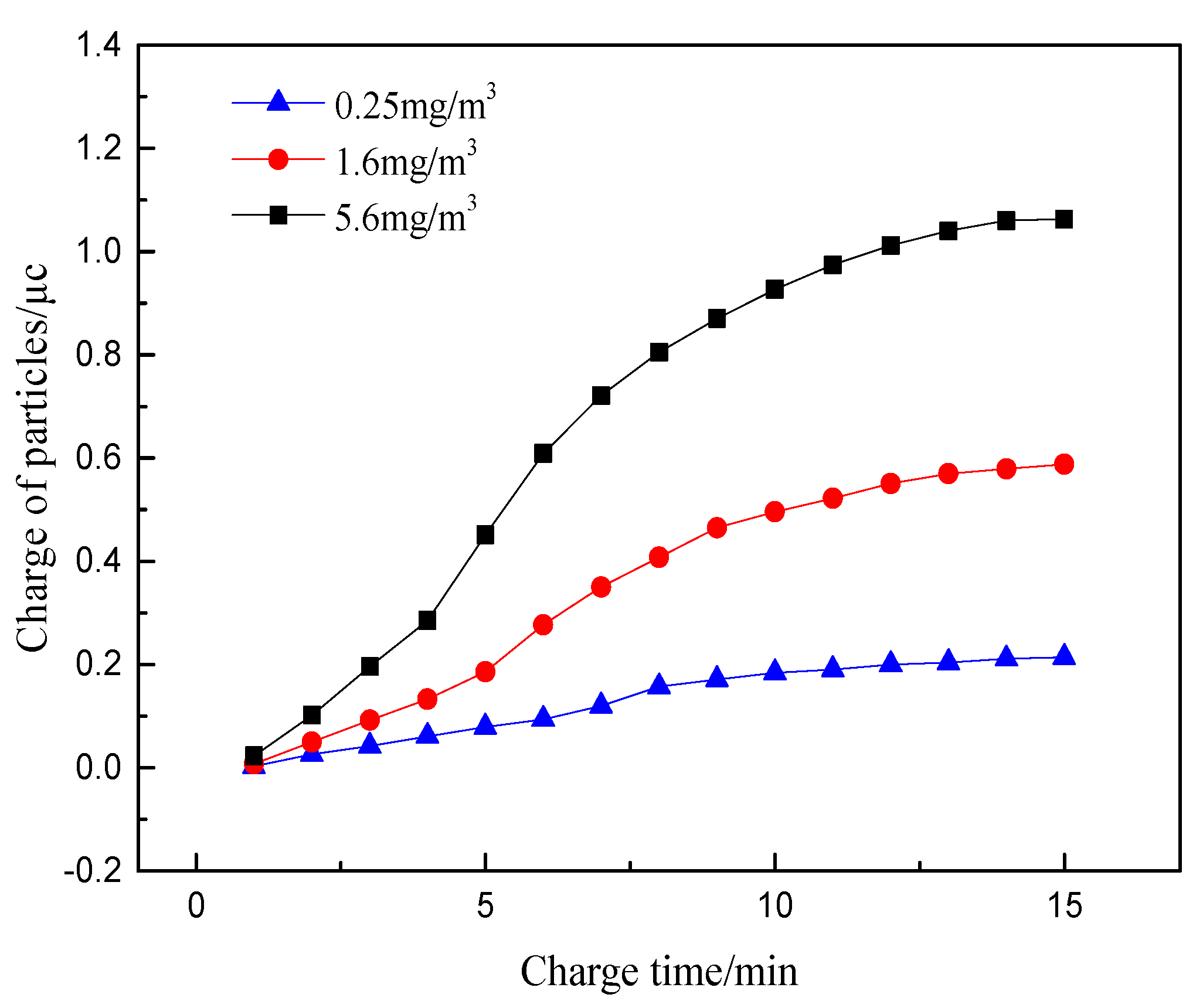
4.4. Particle Concentration
Changes in the operating conditions of diesel engines mainly cause changes in the concentration of particulate matter. The main purpose of the particulate matter sensor is to measure the exhaust gas concentration of the diesel engines in real time. By studying the charge amount of particles in different concentrations, the mechanism of concentration measurement of particle sensor is further studied, which is conducive to improve and optimize particulate matter sensor. The exhaust temperature in the sensor concentration test section, the electrode voltage, the exhaust flow rate, and the particle size are set as 100 °C, 1000 V, 10 m/s, and 100 nm, respectively. The studied particle concentrations are selected as 0.25 mg/m
3, 1.6 mg/m
3 and 5.6 mg/m
3. The variation curve of the charge of particles with time under different concentrations is shown in
Figure 8.
It can be seen that the charge of particulates increases obviously with the increase of particle concentration. This is attributed to the number of charged particles entering the electric field directly affecting the total charge of particles at high exhaust concentration. The space charge density caused by the concentration change has little effect on the electric field strength. The electric field charge and diffusion charge of the particles are not changed greatly with the change of particle concentration. However, the high concentration of charged particles could result in the more frequent collision motion after flowing through the electric field, an expression of further improving the charging effect and producing more obvious changes in the charge.
It can be seen that the charge of particulates increases obviously with the increase of particle concentration. This is attributed to the number of charged particles entering the electric field directly affecting the total charge of particles at high exhaust concentration. The space charge density caused by the concentration change has little effect on the electric field strength. The electric field charge and diffusion charge of the particles are not changed greatly with the change of particle concentration. However, the high concentration of charged particles could result in the more frequent collision motion after flowing through the electric field, in expression of further improving the charging effect and producing more obvious changes in the charge.
On the whole, with the continuous increase of exhaust gas temperature and particle concentration, the charge of particles increases obviously, while the increase of exhaust gas velocity and particle size has little influence on the charge increase of particles. Therefore, exhaust temperature and particle concentration are the main influencing factors of particle charge characteristics.
5. Sensor Charge Characteristic Test
In order to further study the influence of charge characteristics of particles on the output signal value of the sensor, a test bench was built by using the simulation experimental device to analyze the change of particle charge and the output law of the sensor signal under different working conditions. The charge change of the particulate matter and the sensor output signal under actual working conditions are analyzed through the engine bench test.
5.1. Text Programme
A test bench is established to verify the correctness of the simulation. The faraday tube in front of the sensor is used to measure the charge of the uncharged particulate matter to ensure that the total charge of the measured particulate matter is electrically neutral. The charge of the particulate matter flowing through the sensor is measured to obtain the change of the charge of the particulate matter flowing through the sensor under the conditions of different gas temperature, different gas flow rate and different particle size. Since the output signal value of the sensor is mainly positively correlated with the concentration of particulate matter, the exhaust state and the particle size of the particulate matter could affect the signal output of the sensor signal at the same concentration, resulting in a deviation in the output signal value. On this basis, the sensor signal output test is carried out synchronously. Two identical particulate sensors are selected. The particulate signal output at any operating point is repeatedly collected four times, and the four measurement results are averaged to obtain the sensor signal at the changing relationship under different test conditions. This provides data support for the next calibration study. The test is divided into four parts as follows.
The exhaust temperature, the particle size, and the particle concentration are set as 100 °C, 100 nm, and 1.6 mg/m3. The inlet exhaust flow rate is determined as 5 m/s, 10 m/s, 15 m/s, and 20 m/s through the flow adjustment system. The digital charge meter is used to measure the charge of the particles in the faraday tube behind the sensor after turning on the particle generator for 5 min. Meanwhile, the output signal value of the sensor is also measured.
The exhaust gas flow rate, the particle size and the particle concentration are set as 10 m/s, 100 nm, 1.6 mg/m3, respectively. The exhaust temperature is determined as 50 °C, 100 °C, 125 °C and 150 °C through the pipe heater. The digital charge meter is used to measure the charge of the particles in the faraday tube behind the sensor after turning on the particle generator for 5 min. The output signal value of the sensor is also measured.
The exhaust flow rate, the exhaust temperature and the particle concentration are set as 10 m/s, 100 °C and 1.6 mg/m3, respectively. The size of the particles is determined as 20 nm, 50 nm, 100 nm, and 150 nm. The digital charge meter is used to measure the charge of the particles in the faraday tube behind the sensor after turning on the particle generator for 5 min. The output signal value of the sensor was also measured.
The engine bench test is carried out. The torques of 10 N·m, 50 N·m, 75 N·m and 100 N·m at the speed of 1000 r/min are selected as test conditions. The particle charge and the output signal of the sensor under the test conditions are measured. The digital charge meter is used to measure the charge of the particles in the Faraday tube behind the sensor after turning on the particle generator for 5 min. The output signal value of the sensor is also measured.
5.2. Test System and Equipment
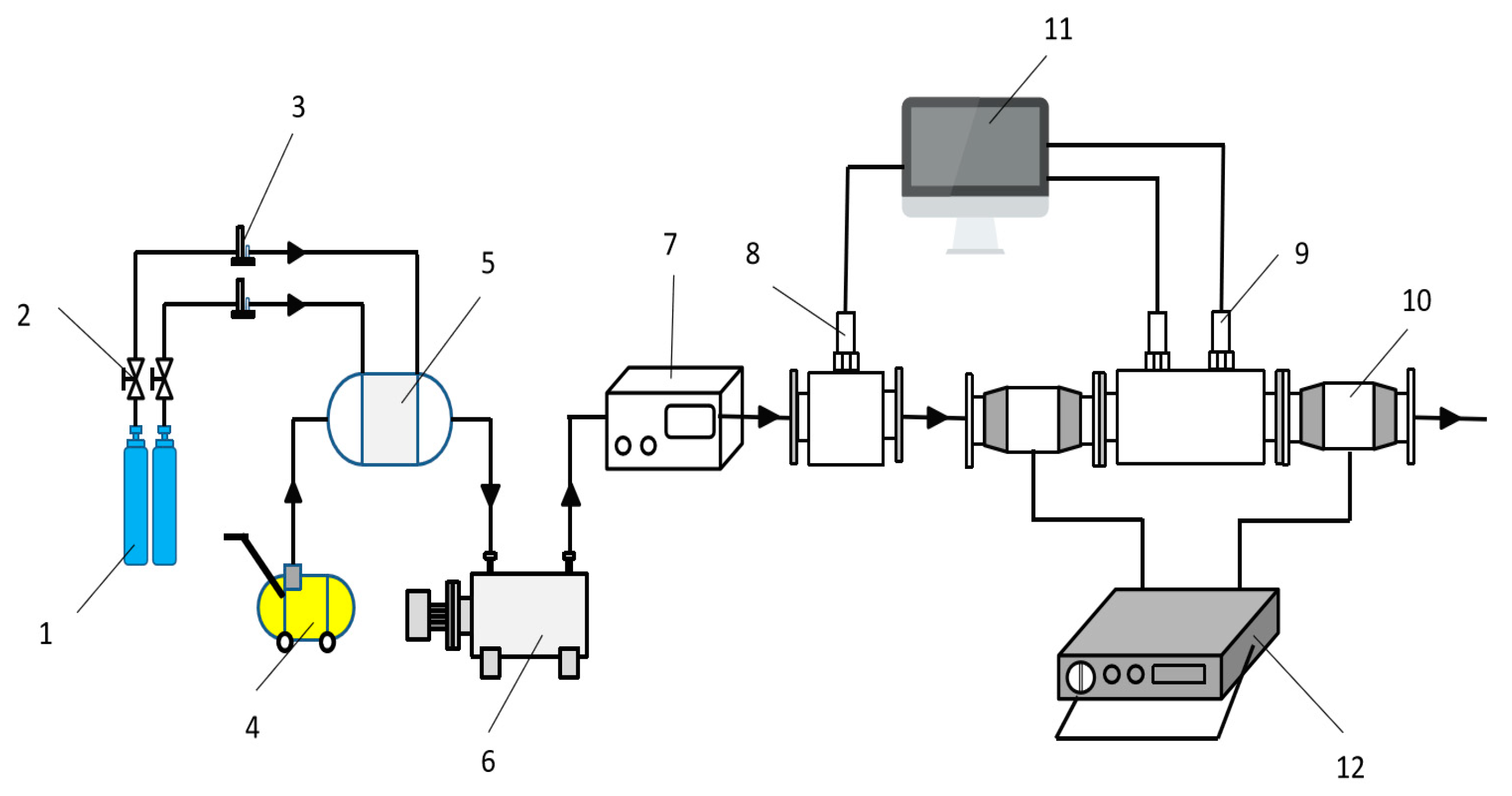
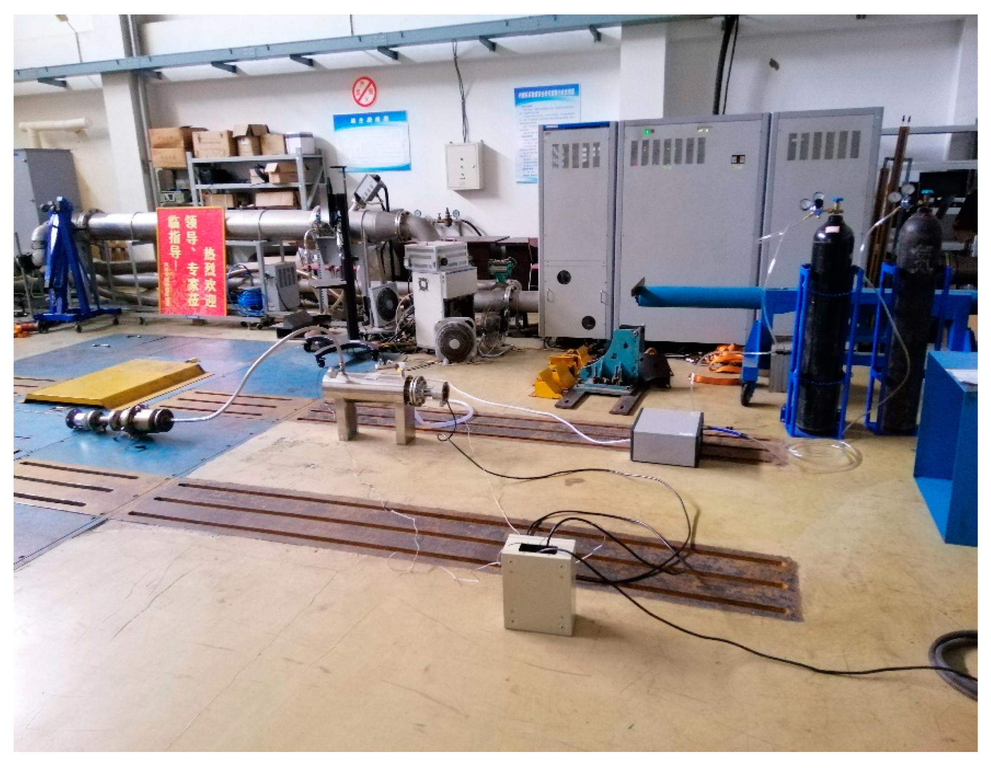
5.2.1. Simulation Test Bench
A simulation test beach, which can simultaneously measure the charge of particles and the signal of particle sensor, is built according to the requirements of the test. As shown in
Figure 9 and
Figure 10, the bench is mainly composed of exhaust simulation system, charge measurement system and sensor signal test system.
In the exhaust simulation system, nitrogen is used as the particle carrier. The gas in the nitrogen cylinder flows into the pipeline heater through the pressure stabilizing tube, and is heated to the temperature required by the test, then flows into the particle generator. The particle generator generates the particle size required by the test which can be used to simulate the exhaust with controllable temperature and particle size after mixing with nitrogen. Finally, the gas is passed into the test system. The back pressure of the gas can be obtained by the pressure sensor. The velocity of the exhaust can be obtained by the ideal gas state equation. The test system is mainly composed of charge measurement system and sensor signal test system. The charge measurement system mainly relies on the Faraday tube and digital charge meter to measure the change of charge amount of particles. The sensor signal test system uses two sensors to measure the change of output signal value of particles under different conditions.
5.2.2. Particulate Matter Generator
DNP3000 particle generator produced by German PALA company was used to produce the particles needed for the test. The generator is able to adjust the generated carbon soot particles rapidly, and the main parameters are shown in
Table 1. The particle generator generates condensed aerosol through high pressure flashover between two graphite electrodes, which is similar to diesel exhaust particles in shape, size, density, surface morphology and refractive index. With flashover, a small amount of graphite material is removed from the high pressure electrode at high temperature and condenses to form the smallest particles. The particle size of primary particles is 3–5 nm, and due to the high quantity concentration, these small particles will agglomerate into clumps. The particle size after agglomeration is 10–150 nm, and the formation of agglomeration can be adjusted in a certain way. After mixing air, the gas particles with a certain concentration are formed to simulate diesel exhaust. Due to a constant flashover voltage, the energy converted in each spark remains constant. Therefore, the particle size distribution and agglomeration amount of particles are also different with the frequency of electric spark. The stability of aerosol generation can be guaranteed by strictly controlling the distance between electrodes in the flashover process, and the quantity and mass flow of particulate can be rapidly regulated by adjusting the spark frequency. The generator is calibrated by particle size spectrometer for engine exhaust emissions (EEPS).
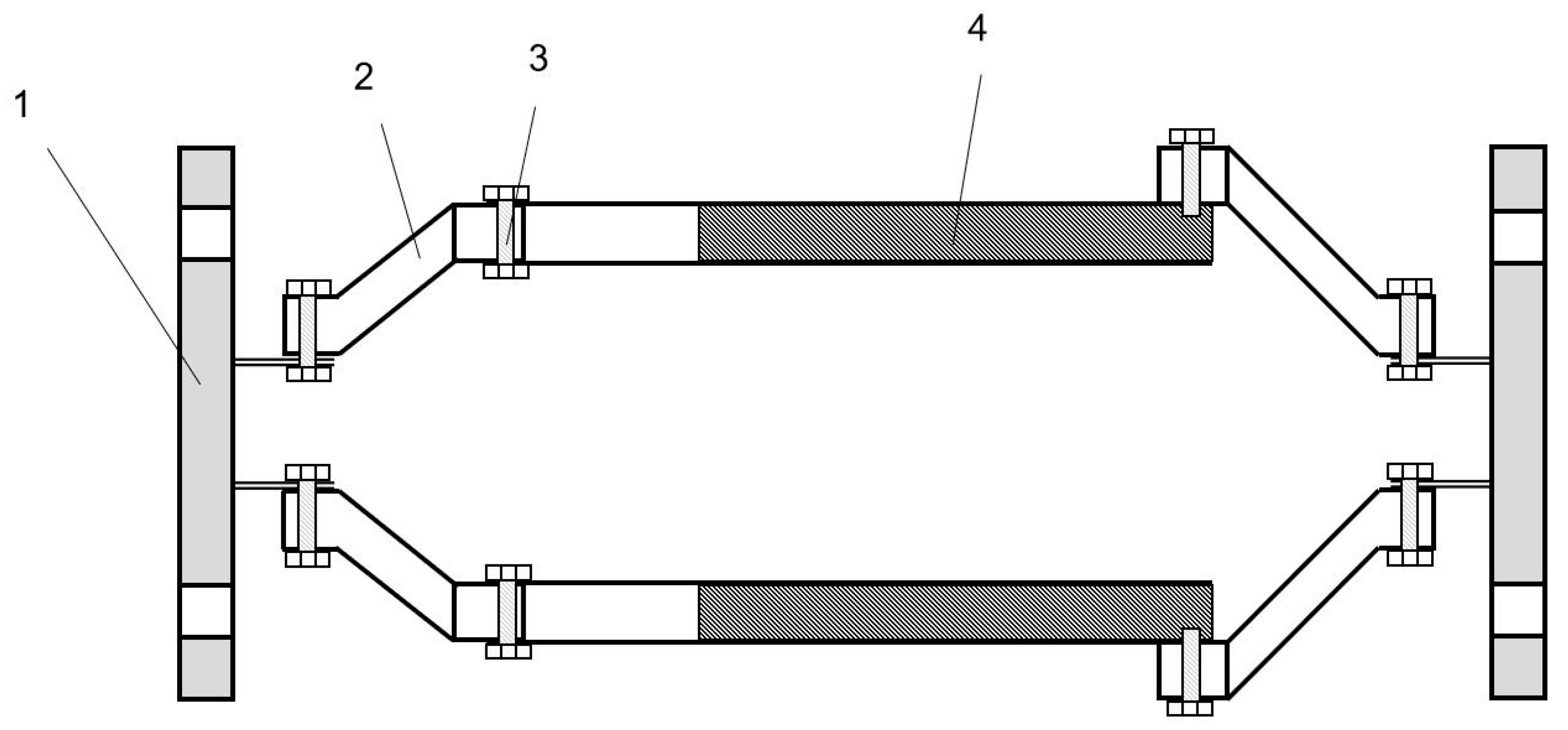
5.2.3. Charge Measuring System
The charging measurement system consists of Faraday tube and EST111A digital charge meter. The Faraday tube needs to be modified in order to facilitate the charge measurement in the test process. The modified Faraday cylinder shall meet the following conditions: (1) it has certain high-temperature and high-pressure resistance performance; (2) good air tightness; (3) high accuracy of charge measurement. The modified Faraday cylinder is shown in
Figure 11.
The prototype of the Faraday tube is a cylindrical vessel consisting of two coaxial cylindrical tubes and an insulating rubber between the layers. The working principle is as follows: the particles will be collected by the inner cylinder when the charged particles enter the Faraday cylinder. The outer cylinder is completely isolated by the insulator and connected to the digital charge meter through the interface, and it is grounded to keep the electrostatic field shielded. When the particles enter the Faraday cylinder, according to the principle of electrostatic induction, the outer surface of the inner cylinder and the inner surface of the outer cylinder will have the same amount of heterogeneous charges. The charge amount of the particles can be obtained by measuring the induced charges generated by the particles entering the sensor. In order to load the Faraday cylinder directly into the test bench, the bottom of the original Faraday cylinder was cut off, and the large and small head made of polyfluoroethylene material was connected with the flange plate. At the same time, all parts were connected with fasteners, and the sealing place was coated with insulation glue, so as to ensure that it had good performance of high temperature and high pressure resistance and air tightness. A glass fiber filter film filter paper is installed at the internal outlet end of the Faraday tube behind the sensor to capture the charged particles entering the tube. Two Faraday tubes were connected to the particle sensor respectively, and the variation trend of the cumulative charge of particles after being charged by the high-voltage electrode of the sensor could be obtained.
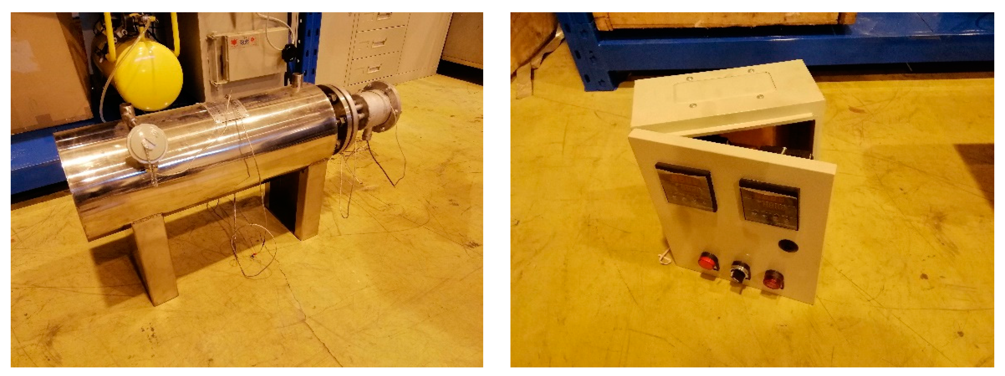
5.2.4. Pipe Electric Heater
Pipe electric heater is a new type of heating equipment developed by Maiheng Electric Equipment Company in recent years. The OCr27A17MO2 high temperature resistance alloy wire and crystalline magnesium oxide powder are formed through compression process, so that the service life of the electric heating element can be guaranteed. The control part is composed of adjustable temperature measuring and constant temperature system with high-precision digital display temperature controller, which ensures the normal operation of electric heater. Scope of application: ammonia heater, air heater, water pipe heater, other kinds of gas, liquid pipe heating equipment.
Pipe electric heater adopts digital display temperature control instrument, solid state relay and temperature measuring element composition measurement, adjustment, control circuit, temperature measurement in the process of electric heating element will pipe outlet temperature of the electric heater electrical signals sent to the digital display temperature control instrument of amplification, after comparing measured temperature value, at the same time the output signal to the solid state relay input, so as to control the heater, the controller has good control precision and regulating characteristics. The interlock device can be used to start and close the electric heater of pipeline remotely.The pipe electric heater and control box used in the test are shown in
Figure 12.
5.3. Analysis of Test Results
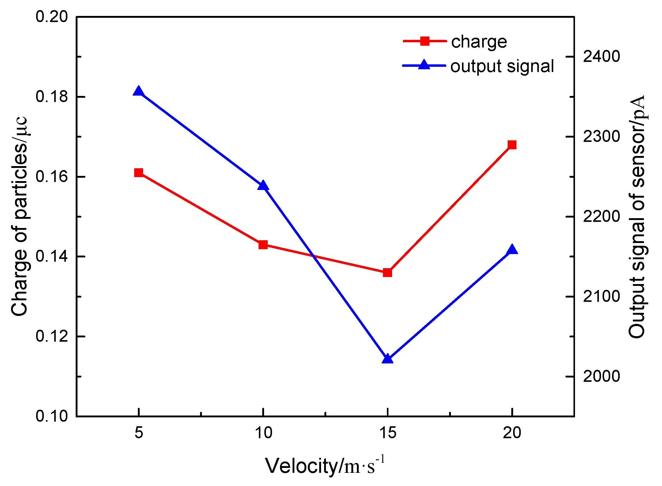
5.3.1. Charge Characteristics of Particles and Sensor Signal Output at Different Flow Rates
Figure 13 shows the relationship between the particle charge and the output signal value of the sensor with the exhaust flow rate. It can be seen from the figure that when the exhaust flow rate increases, the charge of particles decreases first and then increases. It can be known that the increase of flow rate reduces the charging time of particles, thus reducing the charge of particles. Meanwhile, it increases the number of charged particles per unit time. When the exhaust flows at a low rate, few charged particles enter the concentration test section. The charge of single particle is the main factor affecting the total charge. Therefore, the amount of charge decreases as the exhaust flow rate increases. With the increase of exhaust flow rate to a certain value, the number of charged particles increases greatly in unit time. At this time, the number of charged particles takes main part in affecting the charge and thus the charge of particles begins to increase. Only some particles enter the sensor during the test, contributing to the implicit effect of flow rate on the charge of particles.
The output signal value of the sensor is similar to the change of the charge of the particulate matter, which shows the law of decreasing first and then increasing. This is mainly because the charge transmission of the particles in the sensor directly affects the signal output of the sensor. When exhaust flows at a low rate, the particles possess the large charge, and they remain between the plates for a long time. This directly leads to sufficient charge transfer. With the increase of flow rate, the particle charge decreases, and the output signal value of the sensor begins to decrease. When the flow rate increases to a certain stage, the charge of the particulate matter and the output signal value of the sensor exhibit the opposite trend with the above-mentioned law. However, the short retention time of particles in the sensor could result in that some particles do not contact the grounding electrode. Thus, those particles flow out of the concentration test range, which is not conducive to the generation of the output signal of the sensor.
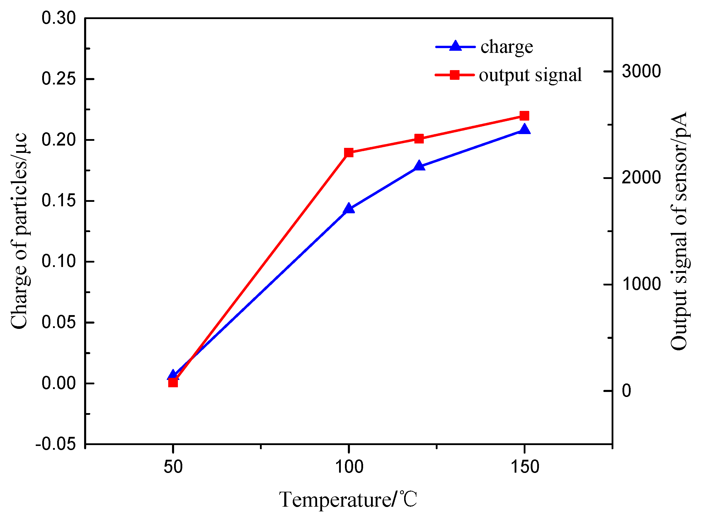
5.3.2. Charge Characteristics of Particles and Sensor Signal Output at Different Temperatures
Figure 14 shows the relationship between the charge of particles and the output signal value of the sensor with the exhaust temperature. It can be seen that when the temperature is too low to reach the halo temperature of the high-voltage electrode, the charge of particles is very small or even close to zero. With the increase of exhaust temperature, the charge of particles exhibits an obvious growth trend. It can be explained that the increase of temperature can increase the electron stroke and discharge intensity, which increase the concentration of charged ions in the concentration test range, intensify the collision and adsorption of particles and charged ions, reduce the specific resistance of particles, and increase the electric field charge and diffusion charge of particles.
The output signal value of the sensor increases with the increase of the exhaust temperature. This is because the increase of temperature not only increases the charge amount of particles, but also strengthens the movement of particles between the plates, which is conducive to the diffusion charge of particles. Meanwhile, the retention charge effect of particles in the concentration test range could be neglected. This can assist the charge transfer of particles between electrode plates and the generation of sensor signal. At the same time, the increase of exhaust temperature leads to the increase of relative permittivity of exhaust gas. The signal value of sensor leakage current is positively related to the relative permittivity of exhaust gas. The increase of exhaust relative permittivity increases the leakage current value of sensor. Thus, the output signal value of the sensor increases with the exhaust gas temperature.
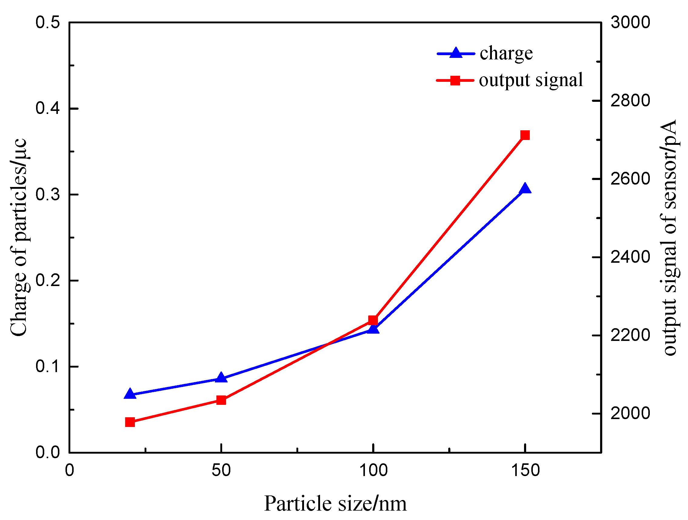
5.3.3. Charge Characteristics of Particles and Sensor Signal Output with Different Particle Sizes
Figure 15 shows the relationship between the particle charge and the output signal value of the sensor with the particle size. It can be seen that the charge of the particles with the increase of particle size, due to the obvious positive correlation between the charge of particles and the particle size. At the same time, the more obvious movement trend of particles with large size results in more frequent particle collisions, and leads to the increase of charge in the identical time.
With the increase of particle size, the output signal value of the sensor increases, and the growth trend is more and more obvious. It can be seen that the output signal value of the sensor is basically consistent with the change rule of the charge. This is because the particles with the large particle size in the concentration test section can be more affected by the electric field force. Meanwhile, due to the increase of the particle size, the exhaust drag force on the particles increases, which lead to the more obvious trend of the migration to the grounding electrode. The migration of the particles assists in the improvement of the charge transmission between the electrode plates and increases the sensitivity of the sensor signal output.
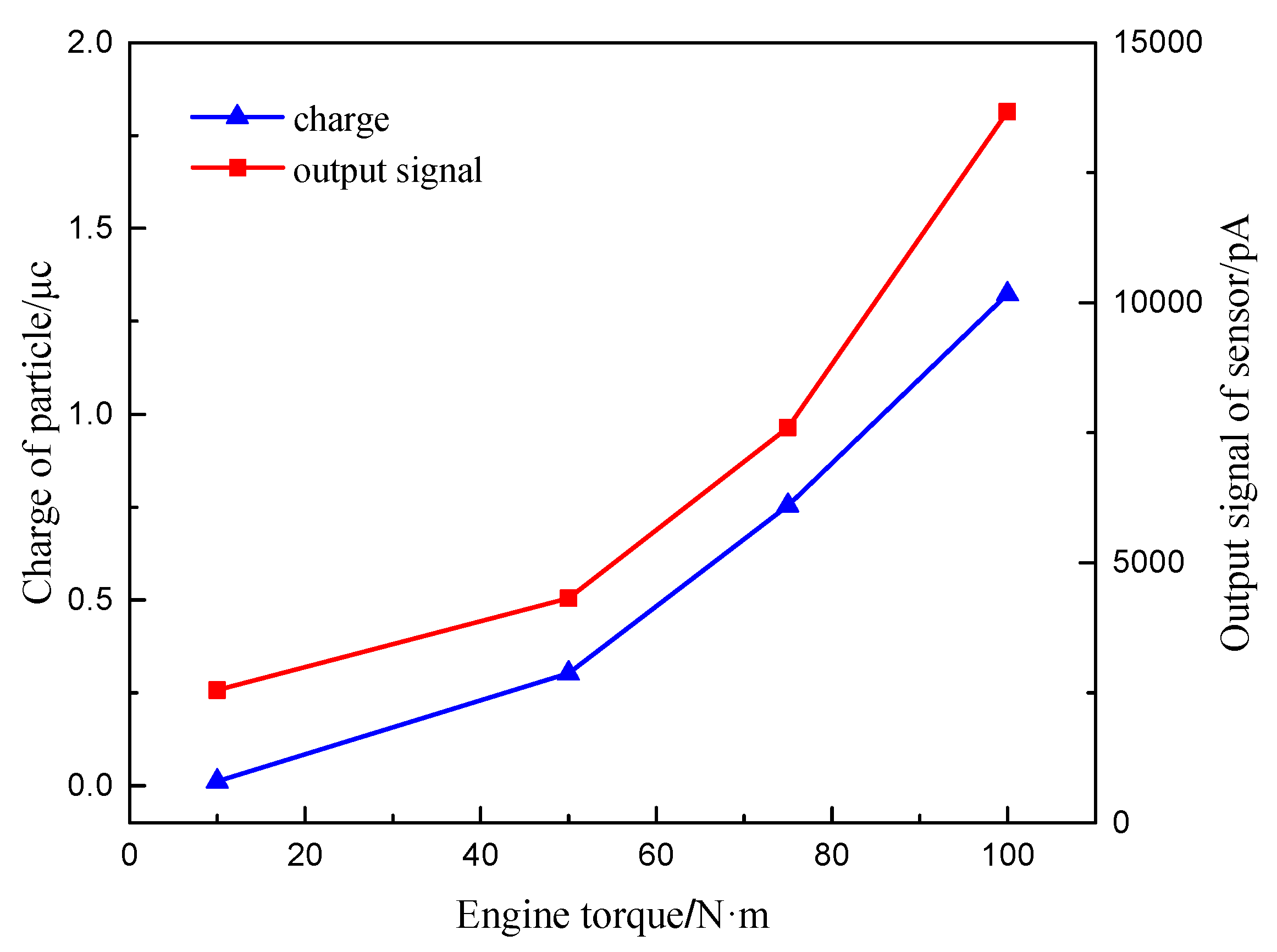
5.3.4. Charge Characteristics of Particles and Sensor Signal Output with Different Working Conditions
Figure 16 shows the relationship between the particle charge and sensor output signal value with different engine torques of 1000 r/min. It can be seen that the charge of the particulate matter increases with the increase of engine torque, because the engine exhaust temperature increases with the increase of the engine torque. The exhaust temperatures under the four operating conditions are 75 °C, 135 °C and 220 °C, respectively. The increase of load leads to the increase of intake flow and exhaust flow rate. Meanwhile, the particle concentration, the median particle size and the surface area of the accumulated and nucleated particles increase with increase of load [
25]. It can be known from the simulation test data that the increase of exhaust temperature, exhaust flow rate and particle size contribute to the increase of the particle charge. Therefore, the charge of the particle increases with engine torque.
The output signal value of the particulate matter sensor also increases with the increase of engine torque, whose growth trend is obvious. This is because as the engine load increases, the section of high concentration mixed fuel increases, resulting in insufficient combustion and increasing exhaust smoke. This directly increases the output signal value of the sensor. Meanwhile, the increase in the charge of the particulate matter also further increases the output signal value of the sensor.


