Sensor Architectures and Technologies for Upper Limb 3D Surface Reconstruction: A Review


Abstract
:1. Introduction
2. 3D Scanning Technologies
2.1. Time-of-Flight Techniques
2.2. Passive Image-Based Techniques
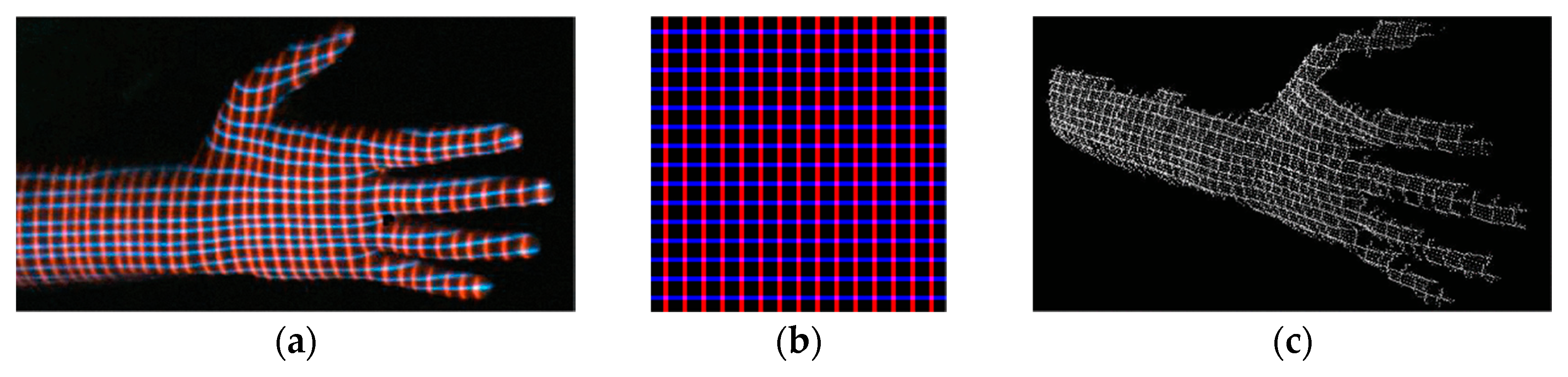
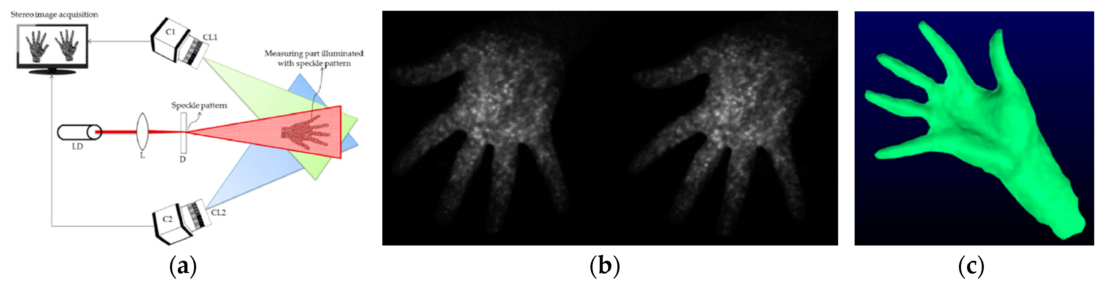
2.3. Structured Light-Based Techniques
2.4. 3D Scanning Technologies Comparison
3. 3D Scanner Architectures for the Reconstruction of Upper Limb Anatomy
3.1. Stationary Scanners
3.2. Hand-Held Real-Time Scanners
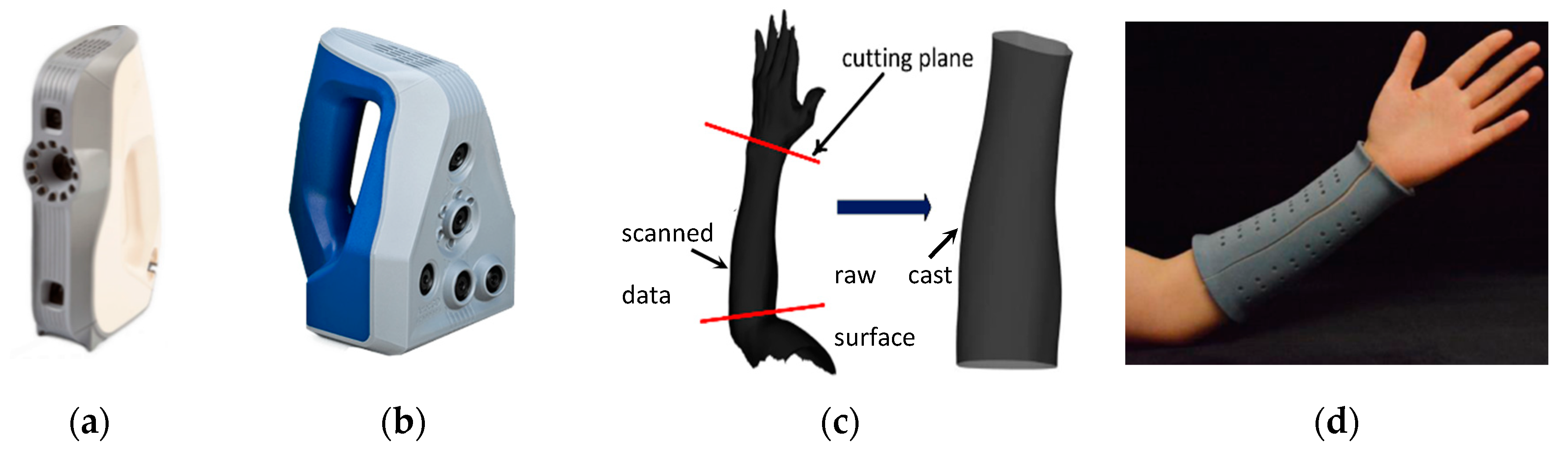
3.2.1. High-End Portable Scanners
3.2.2. Low-End Portable Scanners
3.2.3. Comparison between Hand-Held and Stationary Scanners
3.3. Photogrammetric Body Scanners for the Upper Limb Scanning
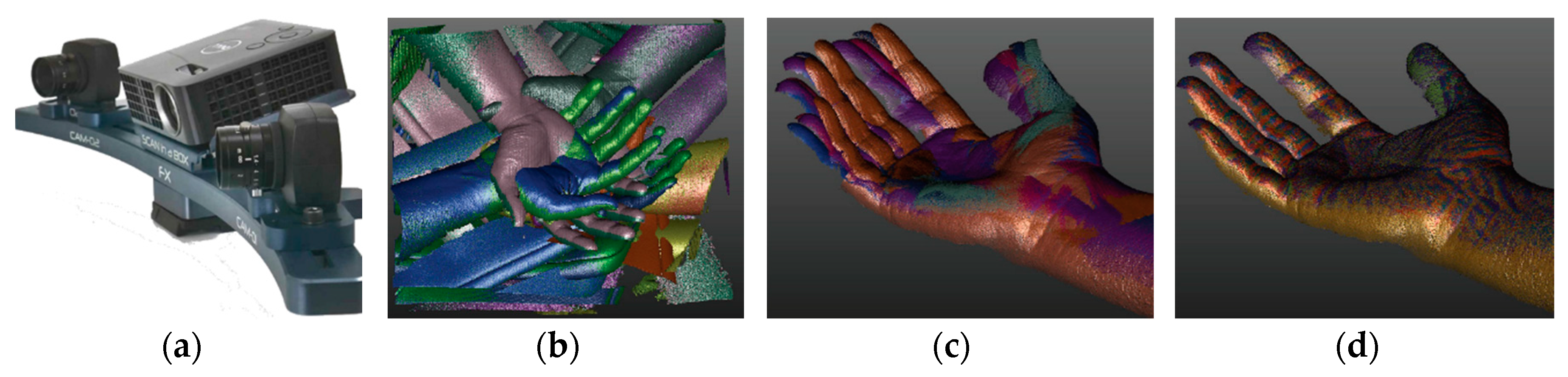
3.4. Custom SL Scanners for Upper Limb Reconstruction
3.5. 3D Scanning Architectures Comparison
4. Discussion
4.1. State of the Art of Upper Limb 3D Scanning
4.2. Trends and Future Challenges
5. Conclusions
Author Contributions
Funding

Conflicts of Interest
Appendix A

| Device | ||
|---|---|---|
Scan-in-a-box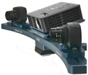 | Technology | Structured light |
| Camera resolution (pxl) | 2M | |
| Point scanning (mm) | 0.08/0.4 | |
| Max accuracy (mm) | 0.08 | |
| Working distance (mm) | 200–1100 | |
| Scanning area (near)/(far) | 100 × 80/500 × 400 | |
| Scanning time (s) | 4 | |
| Weight (kg) | 3 | |
| Dimensions (mm) | 400 × 105 × 92 | |
| Cost (k€) | 3–5 | |
Cronos 3D Dual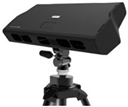 | Technology | Structured light |
| Camera resolution (pxl) | 1600 × 1200 | |
| Point scanning (mm) | 0.09/0.18 | |
| Max accuracy (mm) | 0.02 | |
| Working distance (mm) | 400–1000 | |
| Scanning area (near)/(far) | 150 × 115/300 × 225 | |
| Scanning time (s) | 4 | |
| Weight (kg) | 7.2 | |
| Dimensions (mm) | 540 × 250 × 145 | |
| Cost (k€) | 20–40 | |
Minolta Vivid9i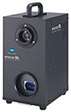 | Technology | Laser triangulation light block method |
| Camera resolution (pxl) | 640 × 480 | |
| Point scanning (mm) | 0.145–2.3 | |
| Max accuracy (mm) | 0.1 | |
| Working distance (mm) | 500–2500 | |
| Scanning area (near)/(far) | 93 × 69/1495 × 1121 | |
| Scanning time (s) | 2.5 | |
| Weight (kg) | 15 | |
| Dimensions (mm) | 221 × 412 × 282 | |
| Cost (k€) | 25–55 | |
Minolta Range7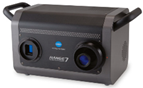 | Technology | Laser triangulation light block method |
| Camera resolution (pxl) | 1280 × 1024 | |
| Point scanning (mm) | 0.08–0.28 | |
| Max accuracy (mm) | 0.08 | |
| Working distance (mm) | 450–800 | |
| Scanning area (near)/(far) | 99 × 79/334 × 267 | |
| Scanning time (s) | 2 | |
| Weight (kg) | 6.7 | |
| Dimensions (mm) | 295 × 190 × 200 | |
| Cost (k€) | 80 | |
REXCAN4 | Technology | Phase-shifting optical triangulation, twin-camera |
| Camera resolution (pxl) | 2M/5M | |
| Point scanning (mm) | 0.03–0.71 | |
| Max accuracy (mm) | 0.03 | |
| Working distance (mm) | 430–1330 | |
| Scanning area (near)/(far) | Not available | |
| Measurement rate (pts/s) | Not available | |
| Weight (kg) | 5 | |
| Dimensions (mm) | 560 × 240 × 170 | |
| Cost (k€) | 20–40 |
| Device | ||
|---|---|---|
Artec Eva | Technology | Structured light |
| Camera resolution (pxl) | 1.3M | |
| Max resolution (mm) | 0.5 | |
| Max accuracy (mm) | 0.1 | |
| Working distance (mm) | 400–1000 | |
| Scanning area (near)/(far) | 214 × 148/536 × 371 | |
| Measurement rate (pts/s) | 2M | |
| Weight (kg) | 0.9 | |
| Dimensions (mm) | 262 × 158 × 63 | |
| Cost (k€) | 14 | |
Go! SCAN 3D | Technology | Structured light |
| Camera resolution (pxl) | Not available | |
| Max resolution (mm) | 0.1 | |
| Max accuracy (mm) | 0.05 | |
| Working distance (mm) | 400 | |
| Scanning area (near)/(far) | 390 × 390/not available | |
| Measurement rate (pts/s) | 1.5M | |
| Weight (kg) | 1.3 | |
| Dimensions (mm) | 89 × 114 × 346 | |
| Cost (k€) | 20 | |
zSnapper Portable | Technology | Structured light |
| Camera resolution (pxl) | 640 × 480 | |
| Max resolution (mm) | 0.3 | |
| Max accuracy (mm) | 0.05 | |
| Working distance (mm) | 350 | |
| Scanning area (near)/(far) | Not available | |
| Measurement rate (pts/s) | Not available | |
| Weight (kg) | 2.3 | |
| Dimensions (mm) | 230 × 130 × 115 | |
| Cost (k€) | 30 | |
Insight3 | Technology | Structured light |
| Camera resolution (pxl) | 1280 × 1024 | |
| Max resolution (mm) | 0.12/0.4 | |
| Max accuracy (mm) | Not available | |
| Working distance (mm) | 150–500 | |
| Scanning area (near)/(far) | 250 × 170/not available | |
| Measurement rate (pts/s) | Not available | |
| Weight (kg) | 2.7 | |
| Dimensions (mm) | 327 × 246 × 74 | |
| Cost (k€) | Not available |
| Device | ||
|---|---|---|
Sense 2 3D Scanner | Technology | Structured light |
| Field of view (hor × ver) | 45° × 57.5° | |
| Accuracy (mm) | 1 (at 0.5 m) | |
| Resolution (pxl) | 640 × 480 | |
| Working distance (mm) | 400–1600 | |
| Frame rate (fps) | 30 | |
| Weight (kg) | 0.59 | |
| Dimensions (mm) | 178 × 129 × 33 | |
| Cost (€) | 500 | |
PrimeSense Carmine 1.09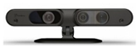 | Technology | Structured light |
| Field of view (hor × ver) | 57.5° × 45° | |
| Accuracy (mm) | 1 (at 0.5 m) | |
| Resolution (pxl) | 640 × 480 | |
| Working distance (mm) | 350–3000 | |
| Frame rate (fps) | 60 | |
| Weight (kg) | 0.22 | |
| Dimensions (mm) | 180 × 25 × 35 | |
| Cost (€) | 300 | |
Kinect sensor V1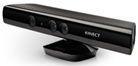 | Technology | Structured light |
| Field of view (hor × ver) | 57° × 43° | |
| Accuracy (mm) | Not available | |
| Resolution (pxl) | 320 × 240 | |
| Working distance (mm) | 400–3500 (near mode) | |
| Frame rate (fps) | 30 | |
| Weight (kg) | 0.55 | |
| Dimensions (mm) | 279.4 × 63.5 × 38.1 | |
| Cost (€) | 100 | |
Kinect sensor V2 | Technology | Time of flight |
| Field of view (hor × ver) | 70° × 60° | |
| Accuracy (mm) | Not available | |
| Resolution (pxl) | 512 × 424 | |
| Working distance (mm) | 500–4500 | |
| Frame rate (fps) | 30 | |
| Weight (kg) | 1.4 | |
| Dimensions (mm) | 249 × 66 × 67 | |
| Cost (€) | 200 | |
Azure kinect | Technology | Time of flight |
| Field of view (hor × ver) | 120° × 120° | |
| Accuracy (mm) | Not available | |
| Resolution (pxl) | 1024 × 1024 | |
| Working distance (mm) | 400–4200 | |
| Frame rate (fps) | 30 | |
| Weight (kg) | 0.44 | |
| Dimensions (mm) | 103 × 39 × 126 mm | |
| Cost (€) | 400 | |
Structure sensor | Technology | Structured light |
| Field of view (hor × ver) | 58° × 45° | |
| Accuracy (mm) | 0.5 (at 0.4 m)/30 (at 3 m) | |
| Resolution (pxl) | 640 × 480 | |
| Working distance (mm) | 400–3500 | |
| Frame rate (fps) | 30–60 | |
| Weight (kg) | 0.095 | |
| Dimensions (mm) | 119 × 28 × 29 | |
| Cost (€) | 400 | |
Structure sensor Mark-II | Technology | Structured light |
| Field of view (hor × ver) | 59° × 46° | |
| Accuracy (mm) | ±0.29% (Plane-fit RMS at 1 m) | |
| Resolution (pxl) | 1280 × 960 | |
| Working distance (mm) | 300–5000 | |
| Frame rate (fps) | 54 | |
| Weight (kg) | 0.065 | |
| Dimensions (mm) | 109 × 18 × 24 | |
| Cost (€) | 500 |
| Device | ||
|---|---|---|
RealSense SR305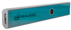 | Technology | Structured light |
| Depth of field of view (hor × ver × diag) | 69° ± 3° × 54° ± 2° | |
| Data stream output resolution (pxl) | 640 × 480 | |
| RGB sensor resolution | 1920 × 1080 | |
| Working distance (mm) | 200–1500 | |
| Frame rate (fps) | 60 | |
| Weight (kg) | 0.07 | |
| Dimensions (mm) | 140 × 26.1 × 12 | |
| Cost (€) | 80 | |
RealSense D415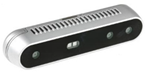 | Technology | Structured light |
| Depth of field of view (hor × ver × diag) | 65° ± 2° × 40° ± 1° × 72° ± 2° | |
| Data stream output resolution (pxl) | 1280 × 720 | |
| RGB sensor resolution | 1920 × 1080 | |
| Working distance (mm) | 300–10,000 | |
| Frame rate (fps) | 90 | |
| Weight (kg) | 0.072 | |
| Dimensions (mm) | 99 × 20 × 23 | |
| Cost (€) | 150 | |
RealSense LiDAR Camera L515 | Technology | LiDAR |
| Depth of field of view (hor × ver × diag) | 70° × 55° (±2°) | |
| Data stream output resolution (pxl) | 1024 × 768 | |
| RGB sensor resolution | 1920 × 1080 | |
| Working distance (mm) | 250–9000 | |
| Frame rate (fps) | 30 | |
| Weight (kg) | 0.1 | |
| Dimensions (diam × height) (mm) | 61 mm × 26 mm | |
| Cost (€) | 300 |
| Device | ||
|---|---|---|
Dimensional Imaging DI3D | Technology | Photogrammetry |
| Max resolution (pxl) | 21 M | |
| Max accuracy (mm) | 0.5 | |
| Working distance (mm) | - | |
| Capture speed (ms) | - | |
| Dimensions (mm) | - | |
| Cost (k€) | 20–140 | |
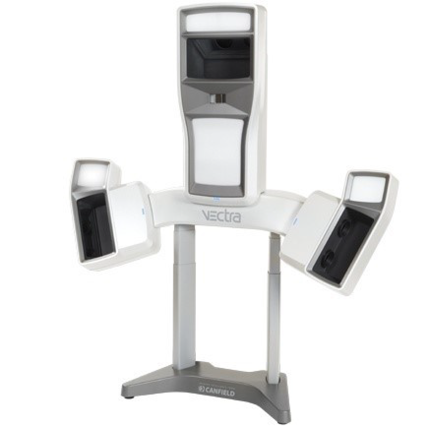
Vectra XT Scanner | Technology | Photogrammetry |
| Max resolution (pxl) | - | |
| Max accuracy (mm) | 1.2 | |
| Working distance (mm) | 500 | |
| Capture speed (ms) | 3.5 | |
| Dimensions (mm) | 1520 × 1410 × 420 | |
| Cost (k€) | 15 | |
3DMDhand System | Technology | Photogrammetry |
| Max resolution (pxl) | - | |
| Max accuracy (mm) | 0.2 | |
| Working distance (mm) | - | |
| Capture speed (ms) | 1.5 | |
| Dimensions (mm) | - | |
| Cost (k€) | 20–50 |
References
- Wiggermann, N.; Bradtmiller, B.; Bunnell, S.; Hildebrand, C.; Archibeque, J.; Ebert, S.; Reed, M.P.; Jones, M.L.H. Anthropometric Dimensions of Individuals with High Body Mass Index. Hum. Factors J. Hum. Factors Ergon. Soc. 2019, 61, 1277–1296. [Google Scholar] [CrossRef] [PubMed]
- Xia, S.; Guo, S.; Li, J.; Istook, C. Comparison of different body measurement techniques: 3D stationary scanner, 3D handheld scanner, and tape measurement. J. Text. Inst. 2018, 110, 1103–1113. [Google Scholar] [CrossRef]
- Kouchi, M. Anthropometric methods for apparel design: Body measurement devices and techniques. In Anthropometry, Apparel Sizing and Design; Elsevier BV: Amsterdam, The Netherlands, 2020; pp. 29–56. [Google Scholar]
- Dianat, I.; Molenbroek, J.; Castellucci, H.I. A review of the methodology and applications of anthropometry in ergonomics and product design. Ergonomics 2018, 61, 1696–1720. [Google Scholar] [CrossRef] [PubMed]
- Lunsford, C.; Grindle, G.; Salatin, B.; Dicianno, B.E. Innovations With 3-Dimensional Printing in Physical Medicine and Rehabilitation: A Review of the Literature. PM R 2016, 8, 1201–1212. [Google Scholar] [CrossRef] [PubMed]
- Barone, S.; Neri, P.; Paoli, A.; Razionale, A.V. Design and manufacturing ofpatient-specific orthodonticappliances by computer-aided engineering techniques. Proc. Inst. Mech. Eng. Part H J. Eng. Med. 2018, 232, 54–66. [Google Scholar] [CrossRef]
- Gajdosik, R.L.; Bohannon, R.W. Clinical Measurement of Range of Motion-Review of Goniometry Emphasizing Reliability and Validity. Phys. Ther. 1987, 67, 1867–1872. [Google Scholar] [CrossRef] [PubMed]
- Paterson, A.M.; Bibb, R.; Campbell, R. A review of existing anatomical data capture methods to support the mass customisation of wrist splints. Virtual Phys. Prototyp. 2010, 5, 201–207. [Google Scholar] [CrossRef] [Green Version]
- Heymsfield, S.B.; Bourgeois, B.; Ng, B.K.; Sommer, M.J.; Li, X.; Shepherd, J.A. Digital anthropometry: A critical review. Eur. J. Clin. Nutr. 2018, 72, 680–687. [Google Scholar] [CrossRef]
- Buonamici, F.; Furferi, R.; Governi, L.; Lazzeri, S.; McGreevy, K.S.; Servi, M.; Talanti, E.; Uccheddu, F.; Volpe, Y. A CAD-based Procedure for Designing 3D Printable Arm-Wrist-Hand Cast. Comput. Des. Appl. 2018, 16, 25–34. [Google Scholar] [CrossRef] [Green Version]
- Barrios-Muriel, J.; Romero, F.; Alonso, F.J.; Salgado, D. Advances in Orthotic and Prosthetic Manufacturing: A Technology Review. Materials 2020, 13, 295. [Google Scholar] [CrossRef] [Green Version]
- Paterson, A.M.; Bibb, R.; Campbell, R.I.; Bingham, G. Comparing additive manufacturing technologies for customised wrist splints. Rapid Prototyp. J. 2015, 21, 230–243. [Google Scholar] [CrossRef] [Green Version]
- Zollhöfer, M.; Stotko, P.; Görlitz, A.; Theobalt, C.; Nießner, M.; Klein, R.; Kolb, A. State of the Art on 3D Reconstruction with RGB-D Cameras. Comput. Graph. Forum 2018, 37, 625–652. [Google Scholar] [CrossRef]
- Erol, A.; Bebis, G.; Nicolescu, M.; Boyle, R.D.; Twombly, X. Vision-based hand pose estimation: A review. Comput. Vis. Image Underst. 2007, 108, 52–73. [Google Scholar] [CrossRef]
- Supančič, J.S.; Rogez, G.; Yang, Y.; Shotton, J.; Ramanan, D. Depth-Based Hand Pose Estimation: Methods, Data, and Challenges. Int. J. Comput. Vis. 2018, 126, 1180–1198. [Google Scholar] [CrossRef] [Green Version]
- Mangiarotti, M.; Ferrise, F.; Graziosi, S.; Tamburrino, F.; Bordegoni, M. A Wearable Device to Detect in Real-Time Bimanual Gestures of Basketball Players During Training Sessions. J. Comput. Inf. Sci. Eng. 2018, 19, 011004. [Google Scholar] [CrossRef]
- Wang, Z. Review of real-time three-dimensional shape measurement techniques. Measurement 2020, 156, 107624. [Google Scholar] [CrossRef]
- Horaud, R.; Hansard, M.E.; Evangelidis, G.D.; Ménier, C. An overview of depth cameras and range scanners based on time-of-flight technologies. Mach. Vis. Appl. 2016, 27, 1005–1020. [Google Scholar] [CrossRef] [Green Version]
- Alenyà, G.; Foix, S.; Torras, C. ToF cameras for active vision in robotics. Sens. Actuators A Phys. 2014, 218, 10–22. [Google Scholar] [CrossRef] [Green Version]
- Hsu, S.; Acharya, S.; Rafii, A.; New, R. Performance of a time-of-flight range camera for intelligent vehicle safety applications. In Advanced Microsystems for Automotive Applications 2006; Springer: Heidelberg/Berlin, Germany, 2006. [Google Scholar]
- Lachat, E.; Macher, H.; Landes, T.; Grussenmeyer, P. Assessment and Calibration of a RGB-D Camera (Kinect v2 Sensor) Towards a Potential Use for Close-Range 3D Modeling. Remote Sens. 2015, 7, 13070–13097. [Google Scholar] [CrossRef] [Green Version]
- Lachat, E.; Macher, H.; Landes, T.; Grussenmeyer, P. Assessment of the accuracy of 3D models obtained with DSLR camera and Kinect v2. Videometr. Range Imaging Appl. XIII 2015, 9528, 95280. [Google Scholar] [CrossRef]
- Gonzalez-Jorge, H.; Rodriguezgonzalvez, P.; MartinezSanchez, J.; Gonzalezaguilera, D.; Arias, P.; Gesto, M.; Díaz-Vilariño, L. Metrological comparison between Kinect I and Kinect II sensors. Measurement 2015, 70, 21–26. [Google Scholar] [CrossRef]
- Foix, S.; Alenya, G.; Torras, C. Lock-in Time-of-Flight (ToF) Cameras: A Survey. IEEE Sens. J. 2011, 11, 1917–1926. [Google Scholar] [CrossRef] [Green Version]
- Microsoft Azure Kinect DK. Available online: https://azure.microsoft.com/en-us/services/kinect-dk/ (accessed on 8 October 2020).
- Lee, C.; Kim, J.; Cho, S.; Kim, J.; Yoo, J.; Kwon, S. Development of Real-Time Hand Gesture Recognition for Tabletop Holographic Display Interaction Using Azure Kinect. Sensors 2020, 20, 4566. [Google Scholar] [CrossRef] [PubMed]
- Albert, J.A.; Owolabi, V.; Gebel, A.; Brahms, C.M.; Granacher, U.; Arnrich, B. Evaluation of the Pose Tracking Performance of the Azure Kinect and Kinect v2 for Gait Analysis in Comparison with a Gold Standard: A Pilot Study. Sensors 2020, 20, 5104. [Google Scholar] [CrossRef] [PubMed]
- Intel RealSense LiDAR Camera L515. Available online: https://www.intelrealsense.com/lidar-camera-l515/ (accessed on 8 October 2020).
- Zhang, R.; Tsai, P.-S.; Cryer, J.; Shah, M. Shape-from-shading: A survey. IEEE Trans. Pattern Anal. Mach. Intell. 1999, 21, 690–706. [Google Scholar] [CrossRef] [Green Version]
- Pertuz, S.; Puig, D.; Garcia, M.A. Analysis of focus measure operators for shape-from-focus. Pattern Recognit. 2013, 46, 1415–1432. [Google Scholar] [CrossRef]
- Hartley, R.I.; Sturm, P. Triangulation. Comput. Vis. Image Underst. 1997, 68, 146–157. [Google Scholar] [CrossRef]
- Tippetts, B.J.; Lee, D.J.; Lillywhite, K.; Archibald, J.K. Review of stereo vision algorithms and their suitability for resource-limited systems. J. Real Time Image Process. 2016, 11, 5–25. [Google Scholar] [CrossRef]
- Barone, S.; Neri, P.; Paoli, A.; Razionale, A.V. Low-frame-rate single camera system for 3D full-field high-frequency vibration measurements. Mech. Syst. Signal. Process. 2019, 123, 143–152. [Google Scholar] [CrossRef]
- Barone, S.; Neri, P.; Paoli, A.; Razionale, A.V.; Bertini, L.; Santus, C. Optical Stereo-System for Full-Field High-Frequency 3D Vibration Measurements Based on Low-Frame-Rate Cameras. In Lecture Notes in Mechanical Engineering; Springer Science and Business Media LLC: Berlin, Germany, 2019; pp. 155–164. [Google Scholar]
- Pan, B. Digital image correlation for surface deformation measurement: Historical developments, recent advances and future goals. Meas. Sci. Technol. 2018, 29, 082001. [Google Scholar] [CrossRef]
- Daanen, H.; Ter Haar, F. 3D whole body scanners revisited. Displays 2013, 34, 270–275. [Google Scholar] [CrossRef]
- Zeraatkar, M.; Khalili, K. A Fast and Low-Cost Human Body 3D Scanner Using 100 Cameras. J. Imaging 2020, 6, 21. [Google Scholar] [CrossRef] [Green Version]
- Grazioso, S.; Selvaggio, M.; Di Gironimo, G. Design and development of a novel body scanning system for healthcare applications. Int. J. Interact. Des. Manuf. 2017, 12, 611–620. [Google Scholar] [CrossRef]
- Meadows, D.M.; Johnson, W.O.; Allen, J.B. Generation of Surface Contours by Moiré Patterns. Appl. Opt. 1970, 9, 942–947. [Google Scholar] [CrossRef]
- Reid, G. Moiré fringes in metrology. Opt. Lasers Eng. 1984, 5, 63–93. [Google Scholar] [CrossRef]
- Huang, P.S.; Zhang, S.; Chiang, F.-P. Trapezoidal phase-shifting method for 3D shape measurement. Opt. East. 2004, 5606, 142–152. [Google Scholar] [CrossRef]
- Jia, P.; Kofman, J.; English, C. Error compensation in two-step triangular-pattern phase-shifting profilometry. Opt. Lasers Eng. 2008, 46, 311–320. [Google Scholar] [CrossRef]
- Barone, S.; Neri, P.; Paoli, A.; Razionale, A.V. 3D acquisition and stereo-camera calibration by active devices: A unique structured light encoding framework. Opt. Lasers Eng. 2020, 127, 105989. [Google Scholar] [CrossRef]
- Ishii, I.; Yamamoto, K.; Doi, K.; Tsuji, T. High-speed 3D image acquisition using coded structured light projection. In Proceedings of the 2007 IEEE/RSJ International Conference on Intelligent Robots and Systems, San Diego, CA, USA, 29 October–2 November 2007; pp. 925–930. [Google Scholar]
- Rusinkiewicz, S.; Hall-Holt, O.; Levoy, M. Real-time 3D model acquisition. Acm Trans. Graph. 2002, 21, 438–446. [Google Scholar] [CrossRef]
- Huang, P.S.; Zhang, C.; Chiang, F.-P. High-speed 3-D shape measurement based on digital fringe projection. Opt. Eng. 2003, 42, 163–168. [Google Scholar] [CrossRef]
- Huang, P.S.; Pan, J.; Chiang, F.-P. Color phase-shifting technique for three-dimensional shape measurement. Opt. Eng. 2006, 45, 013602. [Google Scholar] [CrossRef]
- Su, X.; Chen, W. Fourier transform profilometry. Opt. Lasers Eng. 2001, 35, 263–284. [Google Scholar] [CrossRef]
- Zappa, E.; Busca, G. Static and dynamic features of Fourier transform profilometry: A review. Opt. Lasers Eng. 2012, 50, 1140–1151. [Google Scholar] [CrossRef]
- Huang, L.; Kemao, Q.; Pan, B.; Asundi, A.K. Comparison of Fourier transform, windowed Fourier transform, and wavelet transform methods for phase extraction from a single fringe pattern in fringe projection profilometry. Opt. Lasers Eng. 2010, 48, 141–148. [Google Scholar] [CrossRef]
- Zhang, S. Absolute phase retrieval methods for digital fringe projection profilometry: A review. Opt. Lasers Eng. 2018, 107, 28–37. [Google Scholar] [CrossRef]
- Ben-Hamadou, A.; Soussen, C.; Daul, C.; Blondel, W.; Wolf, D. Flexible calibration of structured-light systems projecting point patterns. Comput. Vis. Image Underst. 2013, 117, 1468–1481. [Google Scholar] [CrossRef]
- Voisin, Y. Calibration of a three-dimensional reconstruction system using a structured light source. Opt. Eng. 2002, 41, 484. [Google Scholar] [CrossRef]
- Lin, H.; Nie, L.; Song, Z. A single-shot structured light means by encoding both color and geometrical features. Pattern Recognit. 2016, 54, 178–189. [Google Scholar] [CrossRef]
- Albitar, C.; Graebling, P.; Doignon, C. Design of a Monochromatic Pattern for a Robust Structured Light Coding. In Proceedings of the 2007 IEEE International Conference on Image Processing, San Antonio, TX, USA, 16–19 September 2007. [Google Scholar]
- Wang, Z.; Zhou, Q.; Shuang, Y. Three-dimensional reconstruction with single-shot structured light dot pattern and analytic solutions. Measurement 2020, 151, 107114. [Google Scholar] [CrossRef]
- Wang, Z.; Yang, Y. Single-shot three-dimensional reconstruction based on structured light line pattern. Opt. Lasers Eng. 2018, 106, 10–16. [Google Scholar] [CrossRef]
- Koninckx, T.; Van Gool, L. Real-time range acquisition by adaptive structured light. IEEE Trans. Pattern Anal. Mach. Intell. 2006, 28, 432–445. [Google Scholar] [CrossRef]
- Pagès, J.; Salvi, J.; Collewet, C.; Forest, J. Optimised De Bruijn patterns for one-shot shape acquisition. Image Vis. Comput. 2005, 23, 707–720. [Google Scholar] [CrossRef]
- Kawasaki, H.; Furukawa, R.; Sagawa, R.; Yagi, Y. Dynamic scene shape reconstruction using a single structured light pattern. In Proceedings of the 2008 IEEE Conference on Computer Vision and Pattern Recognition, Anchorage, AK, USA, 23–28 June 2008; pp. 1–8. [Google Scholar]
- Di Martino, J.M.; Fernandez, A.; Ferrari, J.A. One-shot 3D gradient field scanning. Opt. Lasers Eng. 2015, 72, 26–38. [Google Scholar] [CrossRef]
- Ulusoy, A.O.; Calakli, F.; Taubin, G. In One-shot scanning using de Bruijn spaced grids. In Proceedings of the 2009 IEEE 12th International Conference on Computer Vision Workshops, Kyoto, Japan, 27 September–4 October 2009; pp. 1786–1792. [Google Scholar]
- Khan, D.; Shirazi, M.A.; Kim, M.Y. Single shot laser speckle based 3D acquisition system for medical applications. Opt. Lasers Eng. 2018, 105, 43–53. [Google Scholar] [CrossRef]
- Zhang, S. High-speed 3D shape measurement with structured light methods: A review. Opt. Lasers Eng. 2018, 106, 119–131. [Google Scholar] [CrossRef]
- Van Der Jeught, S.; Dirckx, J.J. Real-time structured light profilometry: A review. Opt. Lasers Eng. 2016, 87, 18–31. [Google Scholar] [CrossRef]
- Zuo, C.; Feng, S.; Huang, L.; Tao, T.; Yin, W.; Chen, Q. Phase shifting algorithms for fringe projection profilometry: A review. Opt. Lasers Eng. 2018, 109, 23–59. [Google Scholar] [CrossRef]
- Li, Z.; Zhong, K.; Li, Y.; Zhou, X.; Shi, Y. Multiview phase shifting: A full-resolution and high-speed 3D measurement framework for arbitrary shape dynamic objects. Opt. Lett. 2013, 38, 1389–1391. [Google Scholar] [CrossRef]
- Zhang, Z.; Towers, D.P.; Towers, C.E. Snapshot color fringe projection for absolute three-dimensional metrology of video sequences. Appl. Opt. 2010, 49, 5947. [Google Scholar] [CrossRef]
- Sitnik, R. Four-dimensional measurement by a single-frame structured light method. Appl. Opt. 2009, 48, 3344–3354. [Google Scholar] [CrossRef]
- Liu, X.; Kofman, J. Real-time 3D surface-shape measurement using background-modulated modified Fourier transform profilometry with geometry-constraint. Opt. Lasers Eng. 2019, 115, 217–224. [Google Scholar] [CrossRef]
- Zhong, J.; Weng, J. Phase retrieval of optical fringe patterns from the ridge of a wavelet transform. Opt. Lett. 2005, 30, 2560–2562. [Google Scholar] [CrossRef] [PubMed]
- Wang, Z.; Zhang, C. Three-Dimensional Hand Reconstruction by Single-Shot Structured Light Line Pattern. IEEE Access 2018, 6, 59881–59890. [Google Scholar] [CrossRef]
- Baronio, G.; Harran, S.; Signoroni, A. A Critical Analysis of a Hand Orthosis Reverse Engineering and 3D Printing Process. Appl. Bionics Biomech. 2016, 2016, 1–7. [Google Scholar] [CrossRef] [Green Version]
- Bonarrigo, F.; Signoroni, A.; Botsch, M. Deformable registration using patch-wise shape matching. Graph. Model. 2014, 76, 554–565. [Google Scholar] [CrossRef] [Green Version]
- Kim, H.; Jeong, S. Case study: Hybrid model for the customized wrist orthosis using 3D printing. J. Mech. Sci. Technol. 2015, 29, 5151–5156. [Google Scholar] [CrossRef]
- Chiu, C.-Y.; Thelwell, M.; Senior, T.; Choppin, S.B.; Hart, J.; Wheat, J. Comparison of depth cameras for three-dimensional reconstruction in medicine. Proc. Inst. Mech. Eng. Part H J. Eng. Med. 2019, 233, 938–947. [Google Scholar] [CrossRef]
- Lin, H.; Shi, L.; Wang, D. A rapid and intelligent designing technique for patient-specific and 3D-printed orthopedic cast. 3D Print Med. 2016, 2, 4. [Google Scholar] [CrossRef]
- Asanovic, I.; Millward, H.; Lewis, A. Development of a 3D scan posture-correction procedure to facilitate the direct-digital splinting approach. Virtual Phys. Prototyp. 2018, 14, 92–103. [Google Scholar] [CrossRef]
- Štefanovič, B.; Michalíková, M.; Bednarčíková, L.; Trebuňová, M.; Živčák, J. Innovative approaches to designing and manufacturing a prosthetic thumb. Prosthetics Orthot. Int. 2020. [Google Scholar] [CrossRef]
- Tzionas, D.; Ballan, L.; Srikantha, A.; Aponte, P.; Pollefeys, M.; Gall, J. Capturing Hands in Action Using Discriminative Salient Points and Physics Simulation. Int. J. Comput. Vis. 2016, 118, 172–193. [Google Scholar] [CrossRef] [Green Version]
- Tagliasacchi, A.; Schröder, M.; Tkach, A.; Bouaziz, S.; Botsch, M.; Pauly, M. Robust Articulated-ICP for Real-Time Hand Tracking. Comput. Graph. Forum 2015, 34, 101–114. [Google Scholar] [CrossRef] [Green Version]
- Izadi, S.; Kim, D.; Hilliges, O.; Molyneaux, D.; Newcombe, R.; Kohli, P.; Shotton, J.; Hodges, S.; Freeman, D.; Davison, A.; et al. In KinectFusion: Realtime 3D Reconstruction and Interaction Using a Moving Depth Camera. In Proceedings of the 24th annual ACM symposium on User interface software and technology, Santa Barbara, CA, USA, 16–19 October 2011; pp. 559–568. [Google Scholar]
- Newcombe, R.A.; Izadi, S.; Hilliges, O.; Molyneaux, D.; Kim, D.; Davison, A.J.; Kohli, P.; Shotton, J.; Hodges, S.; Fitzgibbon, A. KinectFusion: Real-Time Dense Surface Mapping and Tracking. In Proceedings of the 2011 10th IEEE International Symposium on Mixed and Augmented Reality, Basel, Switzerland, 26–29 October 2011; pp. 127–136. [Google Scholar]
- Vitali, A.; Regazzoni, D.; Rizzi, C.; Molinero, G. 3D Scanning Procedure for the Evaluation of Lymphedema of Upper Limbs Using Low-Cost Technology: A Preliminary Study, Design Tools and Methods in Industrial Engineering, Cham, 2020; Rizzi, C., Andrisano, A.O., Leali, F., Gherardini, F., Pini, F., Vergnano, A., Eds.; Springer International Publishing: Cham, Switzerland, 2020; pp. 177–188. [Google Scholar]
- Tong, J.; Zhou, J.; Liu, L.; Pan, Z.; Yan, H. Scanning 3D Full Human Bodies Using Kinects. IEEE Trans. Vis. Comput. Graph. 2012, 18, 643–650. [Google Scholar] [CrossRef] [PubMed] [Green Version]
- Ágústsson, A.; Gislason, M.K.; Ingvarsson, P.; Rodby-Bousquet, E.; Sveinsson, T. Validity and reliability of an iPad with a three-dimensional camera for posture imaging. Gait Posture 2019, 68, 357–362. [Google Scholar] [CrossRef]
- Oranges, C.M.; Madduri, S.; Brantner, P.; Msallem, B.; Giordano, S.; Benitez, B.; Kalbermatten, D.F.; Schaefer, D.J.; Thieringer, F. Three-dimensional Assessment of the Breast: Validation of a Novel, Simple and Inexpensive Scanning Process. In Vivo 2019, 33, 839–842. [Google Scholar] [CrossRef]
- Chu, C.-H.; Wang, I.-J.; Sun, J.-R.; Chien-Hsiou, L. Customized designs of short thumb orthoses using 3D hand parametric models. Assist. Technol. 2020, 1–8. [Google Scholar] [CrossRef]
- Redaelli, D.F.; Barsanti, S.G.; Fraschini, P.; Biffi, E.; Colombo, G. Low-cost 3D devices and LASER scanners comparison for the application in orthopedic centres. ISPRS Int. Arch. Photogramm. Remote Sens. Spat. Inf. Sci. 2018, 953–960. [Google Scholar] [CrossRef] [Green Version]
- Intel RealSense. Available online: https://www.intelrealsense.com/#Products (accessed on 8 October 2020).
- Carfagni, M.; Furferi, R.; Governi, L.; Servi, M.; Uccheddu, F.; Volpe, Y. On the Performance of the Intel SR300 Depth Camera: Metrological and Critical Characterization. IEEE Sens. J. 2017, 17, 4508–4519. [Google Scholar] [CrossRef] [Green Version]
- Carfagni, M.; Furferi, R.; Governi, L.; Santarelli, C.; Servi, M.; Uccheddu, F.; Volpe, Y. Metrological and Critical Characterization of the Intel D415 Stereo Depth Camera. Sensors 2019, 19, 489. [Google Scholar] [CrossRef] [Green Version]
- Koutny, D.; Palousek, D.; Koutecky, T.; Zatocilova, A.; Rosicky, J.; Janda, M. 3D Digitalization of the Human Body for Use in Orthotics and Prosthetics. World Acad. Sci. Eng. Technol. 2012, 6, 690–697. [Google Scholar]
- Volonghi, P.; Baronio, G.; Signoroni, A. 3D scanning and geometry processing techniques for customised hand orthotics: An experimental assessment. Virtual Phys. Prototyp. 2018, 13, 105–116. [Google Scholar] [CrossRef]
- Rosicky, J.; Grygar, A.; Chapcak, P.; Bouma, T.; Rosicky, J. Application of 3D Scanning in Prosthetic and Orthotic Clinical Practice. In Proceedings of the 7th International Conference on 3D Body Scanning Technologies, Lugano, Switzerland, 30 November–1 December 2016; pp. 88–97. [Google Scholar]
- Romero, J.; Tzionas, D.; Black, M.J. Embodied Hands: Modeling and Capturing Hands and Bodies Together. ACM Trans. Graph. 2017, 36, 245. [Google Scholar] [CrossRef] [Green Version]
- Hoevenaren, I.A.; Maal, T.J.; Krikken, E.; De Haan, A.; Bergé, S.; Ulrich, D. Development of a three-dimensional hand model using 3D stereophotogrammetry: Evaluation of landmark reproducibility. J. Plast. Reconstr. Aesthetic Surg. 2015, 68, 709–716. [Google Scholar] [CrossRef] [PubMed]
- Palousek, D.; Rosicky, J.; Koutny, D.; Stoklásek, P.; Navrat, T. Pilot study of the wrist orthosis design process. Rapid Prototyp. J. 2014, 20, 27–32. [Google Scholar] [CrossRef]
- Landau, M.J.; Kim, J.S.; Gould, D.J.; Patel, K.M. Vectra 3D Imaging for Quantitative Volumetric Analysis of the Upper Limb. Plast. Reconstr. Surg. 2018, 141, 80e–84e. [Google Scholar] [CrossRef]
- Zhao, Z.; Wang, T.; Xia, S.; Wang, Y. In Hand-3d-Studio: A New Multi-View System for 3d Hand Reconstruction, ICASSP. In Proceedings of the 2020 IEEE International Conference on Acoustics, Speech and Signal Processing (ICASSP), Toronto, ON, Canada, 4–8 May 2020; pp. 2478–2482. [Google Scholar]
- TUDelft 3D Handscanner. Available online: https://www.tudelft.nl/en/ide/research/research-labs/physical-and-ergonomics-lab/3d-handscanner/ (accessed on 15 January 2020).
- Vectory3. Available online: http://corporate.vectory3.com (accessed on 15 January 2020).
- Carfagni, M.; Furferi, R.; Governi, L.; Servi, M.; Uccheddu, F.; Volpe, Y.; McGreevy, K. Fast and Low Cost Acquisition and Reconstruction System for Human Hand-wrist-arm Anatomy. Procedia Manuf. 2017, 11, 1600–1608. [Google Scholar] [CrossRef]
- Buonamici, F.; Furferi, R.; Governi, L.; Lazzeri, S.; McGreevy, K.S.; Servi, M.; Talanti, E.; Uccheddu, F.; Volpe, Y. A practical methodology for computer-aided design of custom 3D printable casts for wrist fractures. Vis. Comput. 2019, 36, 375–390. [Google Scholar] [CrossRef]
- Li, J.; Tanaka, H. Feasibility study applying a parametric model as the design generator for 3D–printed orthosis for fracture immobilization. 3D Print Med. 2018, 4, 1–15. [Google Scholar] [CrossRef] [Green Version]
- UltraLeap Leap Motion Controller. Available online: https://www.ultraleap.com/tracking/ (accessed on 12 October 2020).


| Technology | Method | Robustness | Resolution | Processing | Real-Time | Accuracy |
|---|---|---|---|---|---|---|
| Time-of-Flight | TOF | Medium | Low | Simple | x | Low |
| Lidar | High | Medium | Simple | x | Low | |
| Passive Image-Based | Depth from shading/focus | Low | Low | Complex | - | Low |
| Stereo vision | Low | High | Medium | x | Medium | |
| Photogrammetry | Low | Low | Complex | x | Low | |
| Structured Light-Based | Multiple frames | High | High | Simple | - | High |
| Single frame | Medium | Medium | Medium | x | High |
| Architecture | Technology | Handling | Acquisition Time | Accuracy | Cost |
|---|---|---|---|---|---|
| Stationary scanners | SL | Low 3–15 kg | Long ≈5 s | Very high 0.02–0.1 mm | Very high 20–80 k€ |
| High-end portable scanners | SL | Medium <3 kg | Short ≈1 s | High 0.05–0.1 mm | High 14–30 k€ |
| Low-end portable scanners | SL, TOF | High <1 kg | Very short 1/30–1/60 s | Low ≈1 mm | Low 100–500 € |
| Depth cameras | SL | Very high <0.1 kg | Very short 1/60–1/90 s | Low ≈1 mm | Low 80–150 € |
| Body scanners | PG | Very low >15 kg | Very short 1.5–3.5 ms | Low 0.2–1.5 mm | High 15–50 k€ |
Publisher’s Note: MDPI stays neutral with regard to jurisdictional claims in published maps and institutional affiliations. |
© 2020 by the authors. Licensee MDPI, Basel, Switzerland. This article is an open access article distributed under the terms and conditions of the Creative Commons Attribution (CC BY) license (http://creativecommons.org/licenses/by/4.0/).
Share and Cite
Paoli, A.; Neri, P.; Razionale, A.V.; Tamburrino, F.; Barone, S. Sensor Architectures and Technologies for Upper Limb 3D Surface Reconstruction: A Review. Sensors 2020, 20, 6584. https://doi.org/10.3390/s20226584
Paoli A, Neri P, Razionale AV, Tamburrino F, Barone S. Sensor Architectures and Technologies for Upper Limb 3D Surface Reconstruction: A Review. Sensors. 2020; 20(22):6584. https://doi.org/10.3390/s20226584
Chicago/Turabian StylePaoli, Alessandro, Paolo Neri, Armando V. Razionale, Francesco Tamburrino, and Sandro Barone. 2020. "Sensor Architectures and Technologies for Upper Limb 3D Surface Reconstruction: A Review" Sensors 20, no. 22: 6584. https://doi.org/10.3390/s20226584