Article

Dominant Loss Mechanisms of Whispering Gallery Mode RF-MEMS Resonators with Wide Frequency Coverage

1
Institute of Semiconductors, Chinese Academy of Sciences, Beijing 100083, China
2
Center of Materials Science and Optoelectronics Engineering, University of Chinese Academy of Sciences, Beijing 100049, China
3
State Key Laboratory of Transducer Technology, Shanghai 200050, China
*
Author to whom correspondence should be addressed.
Sensors 2020, 20(24), 7017; https://doi.org/10.3390/s20247017
Submission received: 9 November 2020 / Revised: 5 December 2020 / Accepted: 6 December 2020 / Published: 8 December 2020
(This article belongs to the Special Issue RF-MEMS Solutions for Advanced Passive Components)

Abstract

:
This work investigates the dominant energy dissipations of the multi-frequency whispering gallery mode (WGM) resonators to provide an insight into the loss mechanisms of the devices. An extensive theory for each loss source was established and experimentally testified. The squeezed film damping (SFD) is a major loss for all the WGMs at atmosphere, which is distinguished from traditional bulk acoustic wave (BAW) resonators where the high-order modes suffer less from the air damping. In vacuum, the SFD is negligible, and the frequency-dependent Akhiezer damping (AKE) has significant effects on different order modes. For low-order WGMs, the AKE is limited, and the anchor loss behaves as the dominant loss. For high-order modes with an extended nodal region, the anchor loss is reduced, and the AKE determines the Q values. Substantial Q enhancements over four times and an excellent f × Q product up to 6.36 × 10¹³ at 7 K were achieved.

1. Introduction

Micro-electro-mechanical system (MEMS) resonators with small occupation, IC compatibility, and lower power consumption have emerged as a key enabling solution to constitute advanced RF-front transceivers for future wireless communications [1,2,3,4,5]. The bulk acoustic wave (BAW) resonators are extremely attractive for their high stiffness and low energy dissipation [6]. Based on high-performance BAW resonators with promising f × Q products [7,8,9,10], many outperforming RF components have been demonstrated, such as MEMS oscillators with low phase noise [11,12,13] and RF channel-select filters with ultra-narrow passband [14,15].
Multi-frequency BAW resonators are highly desired for high-end applications such as multi-clock oscillators and multi-band filters. For some widely-used BAW resonators, it is hard to maintain high f × Q products in high-order modes as the Q values degrade sharply due to the severer anchor loss. For example, in contour mode resonators, the Q of high-order modes was deteriorated by the increasing displacement at the stem-supporting region [16]. In width extensional mode resonators, the Q values in even modes suffer from severe energy loss at the tether attachment point [10]. However, the loss mechanisms of various resonators are different [17]. In some devices, like Lamé mode resonators [18], and composite thin-film piezoelectric-on-substrate (TPoS) resonators vibrating in extensional modes [19], high Q values as well as promising f × Q products have been achieved in high-order modes. Nevertheless, the reported BAW resonators are still operating at single frequencies. The whispering gallery modes (WGMs) with extended nodal region in high-order modes are apt to achieve higher f × Q products owing to the reduced anchor loss, which is superior to contour or extensional modes. In addition, the standing waves formed at the disk periphery are beneficial for setting multiple electrodes to implement multi-mode excitations [20]. In [21,22], WGM based switchable disk resonators have been demonstrated. Distinguished from traditional single-frequency BAW resonators, multiple modes can be simultaneously excited to achieve wide frequency coverages, and the Q values retain over 104 for each mode at atmosphere. To better understand their Q limitations, it is significant to study the distinct loss mechanisms of such devices and explore their potential applications.
The reported work mainly focuses on one or several loss sources on certain order WGMs. The anchor loss of WGM resonators has been qualitatively studied in [23,24], which tends to be negligible with increasing mode order, while the dominant dissipations of the high-order modes have not been clarified. The effects of thermoelastic damping (TED) and phonon-phonon interaction damping (PPID) on WGM resonators were analyzed in [25]. It was theoretically indicated that PPID is more significant than TED and determines the upper limit of the f × Q product. In [26], the anchor loss, TED, and PPID were compared for the 2nd WGM resonator with different supporting configurations at 5 K. It was reported that the anchor loss could still remain dominated. However, for multi-mode WGM resonators with wide frequency coverages, the dominant loss mechanisms of each mode can be different and have not been reported yet; thus, the relevant loss sources should be fully taken into account. In the previous work [22], the energy loss sources for the multi-mode WGM resonators have been preliminarily investigated in different experimental conditions; however, the theoretical models were not built up, although the theoretical analyses are essential for quantitatively evaluating each loss mechanism.
In this work, extensive theoretical models were established and experimentally verified. With promising agreement between the theoretical analysis and experimental results, the main loss sources in different working conditions were clarified. For the first time, the distinct temperature dependences of Q for various order modes were explicitly presented and the limiting loss mechanisms at the cryogenic temperatures could be unveiled. Comprehensive analysis about the energy dissipation of the devices was provided.

2. Design and Fabrication

The disk resonator is surrounded by eight uniformly distributed electrodes at the circumference. Utilizing the one-pair of electrode configuration, i.e., two opposite electrodes, the 2nd to 7th WGMs can be simultaneously excited [22]. The supporting stem is located at the center of the disk, corresponding to the nodal region of the disk; thus, the anchor loss can be minimized [21]. The mode shapes are given in Figure 1a. The resonance frequencies can be calculated by solving the following equations [27]:
[ ψ ( ζ ξ ) n q ] [ ψ ( ζ ) n q ] = ( n q n ) 2 ,
ψ ( x ) = x J n 1 ( x ) J n ( x ) ,   q = ζ 2 ( 2 n 2 2 ) ,
ζ = 2 π f n R ρ ( 2 σ + 2 ) E ,   ξ = 2 1 σ ,
where n is the mode order; Jn is the Bessel function of the first kind; fn refers to the resonance frequency of the nth mode; R denotes the disk radius; and E, ρ, and σ refer to the Young’s modulus, density, and Poisson’s ratio, respectively.
As shown in Figure 1c, with the central disk grounded, an AC signal together with a DC bias voltage were applied to the driving electrode using the bias-T; meanwhile, another DC bias voltage was applied to the sensing electrode to extract the motional current. The span angle of the electrode θ is critical for multi-mode excitations. According to dependence of the motional current on the span angle for each mode, the optimal angle of an individual mode is π/n. A small angle cannot provide sufficient electromechanical couplings for low-order modes, while the large one will suppress the high-order modes. Therefore, a traded-off value of 34° was employed [22]. The three-layer self-aligned process was adopted to batch fabricate the 37 μm and 18 μm-radius WGM resonators [28]. The nano-scale spacing gap of 70 nm was made via the thermal oxidation to reduce the impedance. The low pressure chemical vapor deposition low pressure chemical vapor deposition (LPCVD) device layer with nearly zero stress yielded a higher reliability and reduced energy dissipation. The fabricated resonator is shown as Figure 1b.

3. Theoretical Analysis

The total Q of the MEMS resonators can be expressed as:
1 Q = 1 Q i ,
where i denotes one type of loss mechanism, and the total Q is dominated by the lowest Qi. The most relevant energy dissipation sources of RF-MEMS resonators are: anchor loss, air damping, TED, and PPID [29]. For a comprehensive analysis, each loss source should be individually modeled.

3.1. Anchor Loss

The anchor loss is associated with the acoustic waves radiating away from the resonator through the supporting stem and propagating into the substrate. The energy is thus dissipated. As shown in Figure 2a, the disk is suspended by the anchor stem. The bottom end of the stem is attached to the substrate. The semi-infinite substrate is modeled as the semicircle. The perfectly match layers (PML) are applied at the edge of the substrate to absorb the propagating acoustic waves [30]. For multiple WGMs, the thickness of the PML is set as the corresponding resonance wavelength of each mode. The Comsol Multiphysics was used for simulation. Applying the eigenfrequency analysis to the established model, a complex-valued result can be attained, which consists of a real part referring to the resonance frequency and the imaginary part reflecting the exponential damping of the displacement field. Figure 2a shows the displacement distribution of the 3rd WGM. The Qanchor can be calculated as [31]:
Q a n c h o r = Re ( f n ) 2 Im ( f n ) .

3.2. Squeezed-Film Damping

During the vibration of MEMS resonators, the air is moved in and out of the nano-scale spacing gap alternatively. A varied pressure field is generated, which induces a significant force on the resonator sidewall against the vibration; a portion of energy is thus dissipated. This effect is referred to as the squeezed-film damping (SFD). To evaluate the QSFD, the total energy stored in the device as well as the varied pressure induced energy dissipation should be determined. The stored energy can be calculated using the following equation [32]:
E t o t a l = 1 2 ρ h 0 2 π 0 R [ ω n X ( r , θ ) ] 2 r d r d θ ,
where h is the thickness of the disk, ωn is the angular resonance frequency of the nth mode, and X(r,θ) is the displacement of an arbitrary point in the disk, which can be expressed as [22]:
X ( r , θ ) = Q n V P V i ε 0 R ρ ω n 2 g 0 2 X m o d e ( r , θ ) φ 2 φ 2 X mod e ( r , θ ) d θ 0 2 π 0 R [ X m o d e ( r , θ ) ] 2 r d r d θ ,
where Vp, Vi, and Qn are the DC bias voltage, AC voltage amplitude, and the quality factor of the nth mode, respectively; ε0, φ, and g0 denote permittivity, the span angle of electrode, and the spacing gap, respectively; and Xmode is the normalized mode shape function [32]:
X mode = [ d d r J n ( k n r R ) + n r N n M n J n ( h n r R ) ] cos n θ ,
where kn and hn are the frequency associated parameters, which can be expressed as:
k n = ω n R E ρ ( 1 υ 2 ) , h n = ω n R E 2 ρ ( 1 + υ ) .
The relationship between parameters Mn and Nn is [20]:
N n M n = J n ( k n ) J n ( h n ) 2 k n J n 1 ( k n ) J n ( k n ) + h n 2 2 n ( n + 1 ) [ h n J n 1 ( h n ) J n ( h n ) ( n + 1 ) ] 2 n .
Then, the energy dissipation due to the SFD should be extracted. The varied pressure inside the gap is described through the Reynold’s equation [33]:
P a 2 ( δ p ) 12 η e f f g 0 2 ( δ p ) t = 12 η e f f g 0 3 d X ( R , θ , t ) d t ,
where δp, Pa, and X(R,θ,t) are the variation pressure, ambient pressure, and time-harmonic displacement at the circumference of the disk, respectively, and ηeff is the effective viscosity, which can be expressed as [34]:
η e f f = η 0 1 + 9.639 K n 1.159 ,
where η0 denotes the viscosity in atmosphere, and Kn is the Knudsen number associated with the ambient pressure:
K n = P 0 P a λ 0 g 0 ,
where λ0 refers to the mean free path at normal atmospheric pressure P0.
The varied pressure field of the 7th WGM is given in Figure 2b. Furthermore, with the varied pressure field and the displacements at the circumference numerically solved, the energy dissipation per period Wloss can be extracted according to the following equation:
W l o s s = 0 T n ω n ( S δ p X ( R , θ , t ) d S ) d t ,
where Tn is the vibrational period of the nth mode, and S refers to the area of the disk sidewall. The QSFD can be calculated via:
Q S F D = 2 π W t o t a l W l o s s .

3.3. Thermal Elastic Damping

The TED results from the irreversible heat flow arising from the temperature gradients associated with the differential volumetric changes [35]. For an isotropic thermoelastic solid with arbitrary geometrical shapes, the temperature distribution should be firstly attained via the thermodynamic equation [36,37]:
κ 2 T C v T t α ( 3 λ + 2 μ ) T r e f ( x u t + y v t + z w t ) = 0 ,
where Cv and κ are the volumetric heat capability and thermal conductivity [38], respectively; u, v, and w are the displacements in the x, y, and z axes; λ and μ refer to the elastic Lamé parameters; Tref and T denote the ambient and distributed temperature, respectively; and α is the thermal expansion coefficient [39]. Then, the temperature distribution should be incorporated into the mechanical domain. Taking the thermal-mechanical equation in the x direction as an example, the expression takes the form as:
ρ 2 u t 2 = µ ( 2 u x 2 + 2 u y 2 + 2 u z 2 ) + ( λ + µ ) ( 2 u x 2 + 2 v x y + 2 w x z ) α ( 3 λ + 2 µ ) T x .
Based on the coupling equations, with the reference temperature T0 given, similar to (2), a complex ω can be obtained and the Q can be extracted. The temperature distribution of the 5th WGM is shown in Figure 2c.

3.4. Phonon-Phonon Interaction Damping

The phonon-phonon interaction damping (PPID) arises from the scattering of the acoustic phonons. When the sound wavelength (λs) is significantly larger than the phonon mean free path, i.e., fτph << 1, where τph is the thermal relaxation time, the acoustic wave is assumed to interact with the whole ensemble of thermal phonons. This process is referred as the Akhiezer regime (AKE), which is valid for resonance frequencies within hundreds of MHz. On the contrary, if λs is less than the mean free path, the acoustic quanta will interact with the lattice phonons individually, and the process is referred as the Landau Rumer regime (L-R) [38,40], which is valid for very high frequencies exceeding GHz. The WGM resonators with frequencies ranging from 53 to 362 MHz are vibrating in the AKE regime. The QAKE takes the form as [41]:
Q A K E = ρ v a 2 C v T γ e f f 2 1 + ( ω n τ p h ) 2 ω n τ p h ,
where va and γeff are the averaged sound velocity and effective Grüneisen parameter, respectively. The γeff characterizes the phonon frequency variations when the crystal volume is changed [42], which is dependent on the mode shape, material properties, crystal orientation, wave propagation direction, and so on [43]. In this work, an averaged value of 0.51 was employed [44]. The relaxation time τph takes the form as [41]:
τ p h = 3 κ C v V D 2 ,
where VD, the mean Debye velocity, can be determined by:
1 V D 3 = 1 V l 3 + 2 V t 3 ,
where Vl and Vt are the longitudinal and transverse velocities, respectively [44]. It should be noted that in the Akhiezer regime, QAKE is proportional to f−1 for longitudinal waves, and proportional to f−0.75 for transverse waves [38]. For WGMs with both the P- and S-wave contributed, the QAKE could have a complicated frequency-dependence of f-r with r between 0.75 and 1. As can be seen, QAKE still decreases monotonically with the frequency. In addition, thermal conductivity κ varies with the ambient temperature and reduces at lower temperatures [45]. According to Equations (18) and (19), at cryogenic temperatures, the AKE will be effectively suppressed and the AKE-dominated vibrating modes will gain substantial Q enhancements. To sum up, despite the relatively complicated dependence of QAKE on the temperature and frequency, (18) is sufficient to evaluate QAKE values at different temperatures and provides a deep understanding about the distinct AKE effects on multi-mode resonators. The material parameters for different Q calculations are summarized in Table 1.

4. Results and Discussions

A series of measurements were accomplished to characterize the loss mechanisms of WGM resonators in different conditions. The measurement setup is shown in Figure 1c.

4.1. Resonator Performance in Air

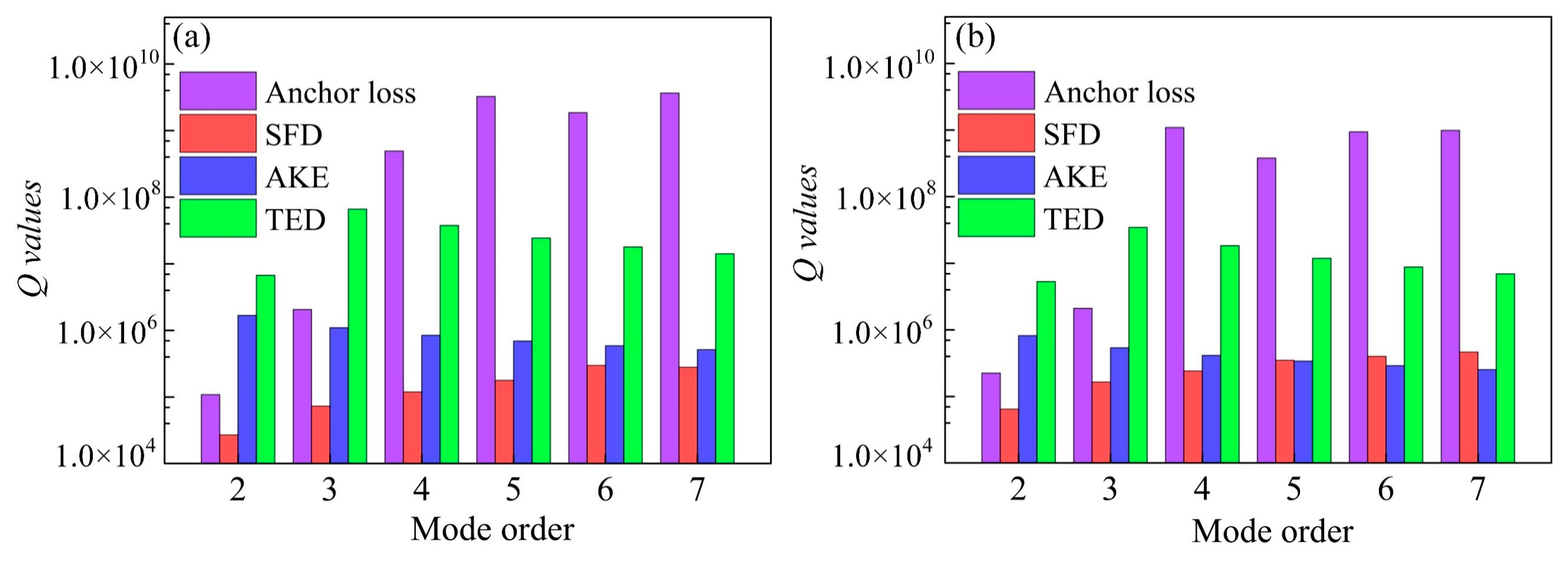
A group of resonators were firstly tested at atmosphere; the measured Q values are summarized in Table 2. For 37 and 18 μm-radius resonators, the calculated Q values using Equations (1)–(3) match well with the measured ones. The discrepancies can be attributed to the slight differences between the real and theoretical parameter values, process tolerances, and so on. The Q values of all the modes up to the 7th WGM maintain around 104, indicating that the anchor loss could not be a major loss source for the high-order modes. The Qanchor values of each mode for both 37 and 18 μm-radius devices were simulated based on the described model in Section 3, Part 1. As shown in Figure 3, the Qanchor of the 2nd to 4th modes rises up from 105 to 109 as the nodal region is expanding towards the circumference, and then it retains around 109 for the 4th to 7th modes. These results infer that the anchor loss is negligible in high-order WGMs.
It should be noted that for WGMs, along the radial direction, the normalized motion at a given point tends to decrease with the increasing mode order [21]; thus, the Qanchor values are expected to rise with the mode order. However, the simulated Q values do not increase monotonously. Additionally, supposing that the energy within the stem region is all dissipated, the ratio of the leakage energy to the total energy takes the form as:
E s t e m E t o t a l = 1 2 ρ h 0 2 π 0 R s [ ω n X ( r , θ ) ] 2 r d r d θ 1 2 ρ h 0 2 π 0 R [ ω n X ( r , θ ) ] 2 r d r d θ = 0 2 π 0 R s [ ω n X mod e ( r , θ ) ] 2 r d r d θ 0 2 π 0 R [ ω n X mod e ( r , θ ) ] 2 r d r d θ ,
where Rs refers to the stem radius. Assuming β = r R and substituting Equation (8) into (21) yields:
E s t e m E t o t a l = 0 2 π cos n θ d θ 0 R s R [ d d β J n ( k n β ) + n β N n M n J n ( h n β ) ] 2 β d β 0 2 π cos n θ d θ 0 1 [ d d β J n ( k n β ) + n β N n M n J n ( h n β ) ] 2 β d β .
The stem radii of the 37 and 18 μm-radius resonators are 3 μm and 1.5 μm, respectively. Pursuant to (22), with similar stem to disk radii ratios, the Qanchor values of each mode should be very close; however, the simulations exhibit clear difference. The discrepancies can be caused by the supporting stem, which is modeled as a longitudinal rod subjected to the time-harmonic vibrations with the resonance frequency fn. The height and radius of the supporting stem affect the wave propagations from the disk to the substrate, leading to the Qanchor values different from the expectation [46].

4.2. Resonator Performance in Vacuum

For WGM resonators with a nanoscale spacing gap, the squeezed film damping could be significant. To provide a clear comparison between the SFD and anchor loss, the QSFD values of the 18 and 37 μm-radius resonators were calculated and plotted in Figure 3 to compare with the Qanchor values. As can be seen, the QSFD values are much smaller than the Qanchor values even in the 2nd mode with severe anchor loss. Clearly, there is more SFD than the anchor loss, especially in the high-order WGMs. Substantial Q enhancements are expected for all the WGMs in vacuum.
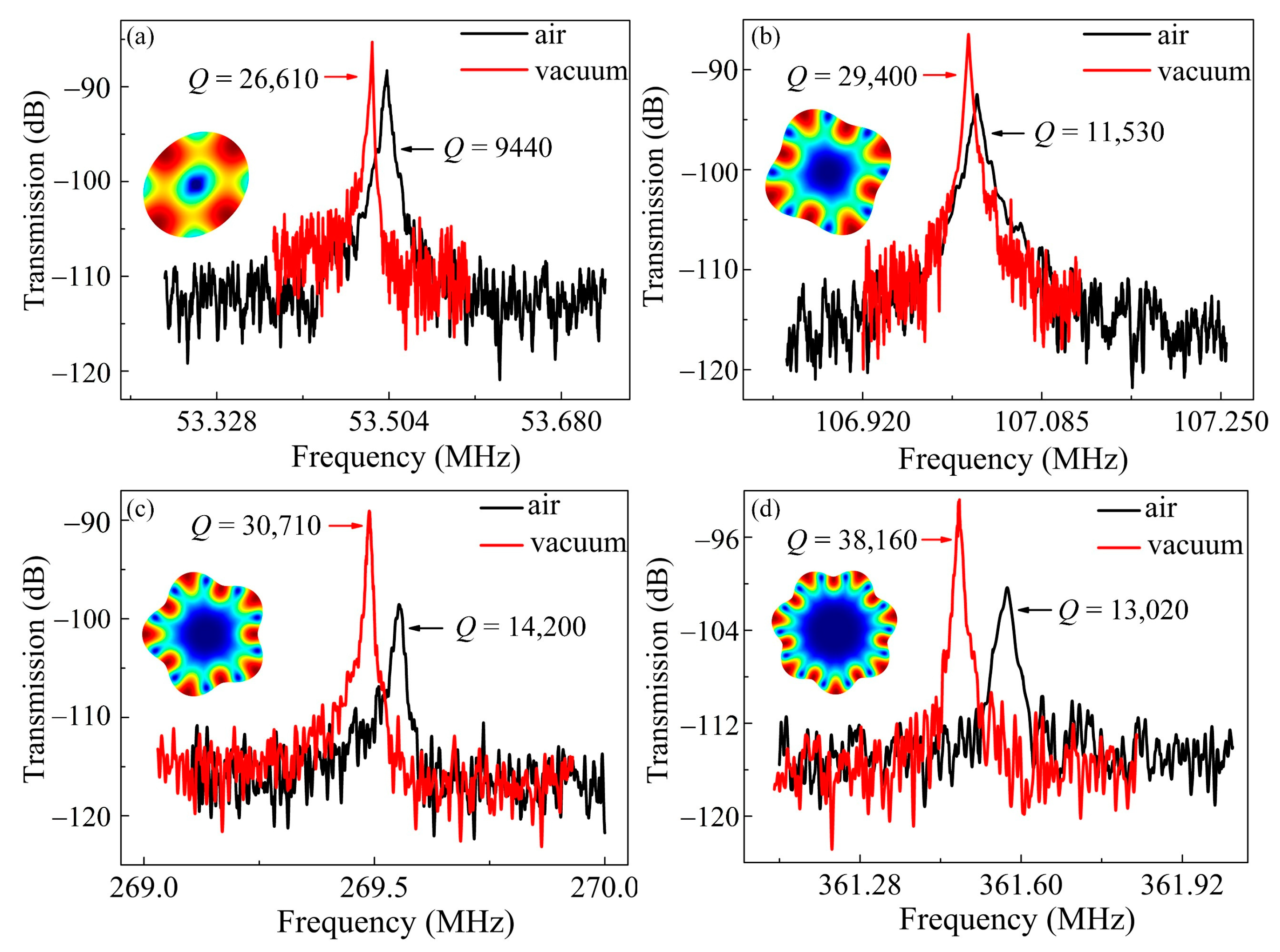
The devices were subsequently tested in vacuum. A Lakeshore CRX-4K probe station was employed to provide a high vacuum of 8 × 10⁻⁵ bar. For different WGMs, Q enhancements exceeding 2 times were achieved. As shown in Figure 4a,b, for the 2nd and 4th WGMs of the 37 μm-radius resonator, the Q improves from 9440 to 26,610, and from 11,530 to 29,400, respectively. The similar tendency can be obtained for the 18 μm-radius counterparts. Figure 4c,d show that for 5th and 7th WGMs, the Q improves from 14,200 to 30,710, and from 13,020 to 38,160, respectively. An outperforming f × Q product up to 1.38 × 10¹³ was implemented. The substantial Q enhancements of all the WGMs infer that the SFD is a major loss source even for high-order modes. By contrast, the traditional high-order BAW modes are insensitive to the SFD due to the increased stiffness [16,47]. The resonance frequency shift could be attributed to the effect of hydrostatic pressure. The bulk elastic modulus goes down with the decreasing pressure [48], which leads to a reduced frequency.
Despite the fact that the anchor loss and SFD are negligible in vacuum, the Q values of the high-order WGMs are not as high as expected. There could be some other loss sources that limit the Q enhancements of high-order WGMs. The TED and AKE, which could be more significant at higher frequencies, should be taken into account.

4.3. Resonator Performance at Cryogenic Temperatures

The TED and AKE can be effectively suppressed at cryogenic temperatures. The high-order WGMs, which could be dominated by these two mechanisms, would exhibit higher Q enhancements at low temperatures. For both two types of resonators, the Q values were measured with the temperatures ranging from 7 K to 293 K, and the step was set as 16 K.
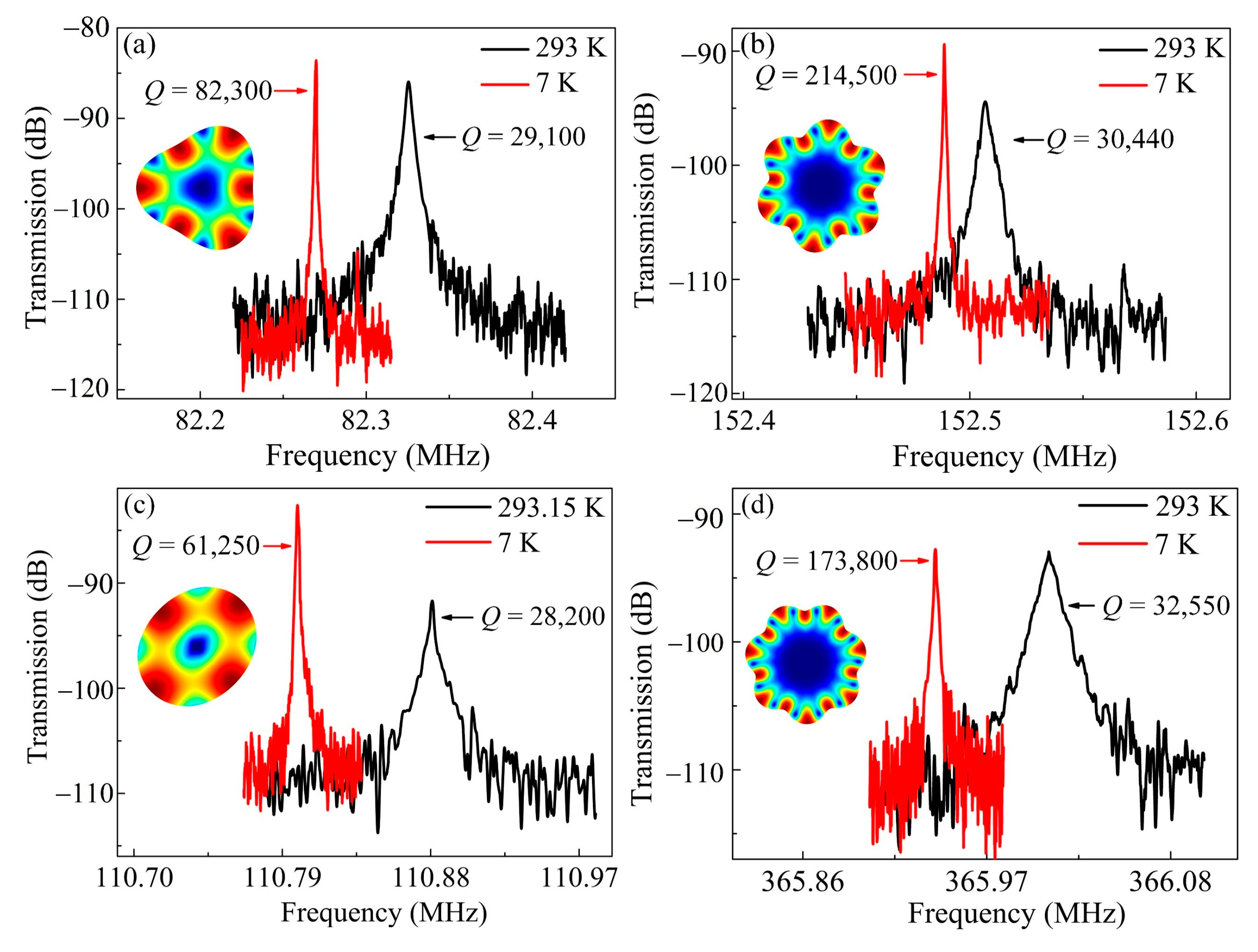
The measured frequency responses for the 37 and 18 μm-radius resonators at 7 K are given in Figure 5. As can be seen, the Q of the 3rd mode for the 37 μm-radius resonator at 7 K is 82,300, and relative to the Q of 29,100 at room temperature, the enhancement is only 2.83 times (Figure 5a). By contrast, the Q in the 6th mode boosted from 30,440 to 214,500 at 7 K (Figure 5b), which achieves a promising enhancement of 7.05 times. The 18 μm-radius counterparts exhibit the similar tendency. As shown in Figure 5c,d, the Q values of the 2nd and 7th WGMs at room temperature were 28,200 and 32,550, and were raised up to 61,250 and 173,800 at 7 K, corresponding to the enhancements of 2.17 and 5.34 times, respectively. Besides, an outperforming f × Q product up to 6.36 × 10¹³ of the 7th WGM was implemented at 7 K. The frequency shifts are determined by the frequency-temperature (f-T) coefficients at cryogenic temperatures. For highly p-doped shear mode resonators, the f-T curve is a parabola over a wide temperature range, wherein the frequency goes down with the decreasing temperature in the low temperature range [49]. For highly p-doped WGM resonators with mainly shear deformations, the f-T coefficient tends to be positive at cryogenic temperatures, which gives rise to the frequency reduction.
As expected, the Q enhancements of high-order WGMs benefit more from the temperature reduction. Given that both AKE and TED dramatically decrease at low temperatures, these two sources are difficult to be distinguished experimentally, but can be separated theoretically. The QAKE and QTED values of the 37 and 18 μm-radius resonators were calculated using the established models and also plotted in Figure 3 to provide a clear comparison. As can be seen, the QAKE decreases monotonically with the frequency and tends to approach the SFD in high-order modes. Therefore, the AKE contributes to a substantial portion of energy dissipation for high-order WGMs at room temperature, which leads to their limited Q improvements in vacuum. As for TED, it is identified as a negligible loss source in BAW modes, especially in volume conserved WGMs [6], which is verified via the calculated results as shown in Figure 3. It is worth mentioning that both the AKE and TED are not simply inversely proportional to the temperature [39] since the thermal expansion coefficient α in (16) and thermal conductivity κ in (19) are temperature-dependent variations. However, as demonstrated in [26], the QAKE retains much lower than the QTED from 5 K to 293 K; hence, the TED can be ruled out as a major loss source for the devices.
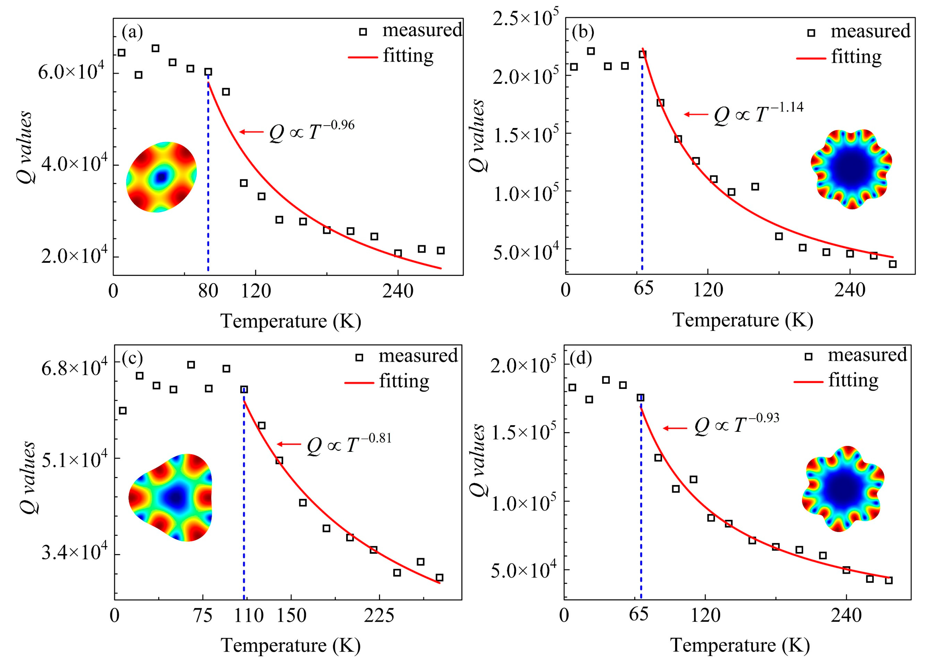
It should be noted that with AKE suppressed at lower temperatures, the other loss mechanisms could override it and become dominated. Thus, there could be a turnover temperature in the Q-T curve of an individual WGM. Between the turnover and room temperatures, the Q would decrease with the increasing temperature, which could take a form as an approximate negative power function. Given that the high-order modes have more striking Q enhancements, their Q dependences on the temperature are expected to be stronger. On the other hand, when the temperature is lower than the turnover point, the Q would be insensitive to the temperature. For high-order modes, since the AKE contributes more energy dissipation, it would be dominated within a wider temperature range. Therefore, the turnover temperatures of the high-order WGMs are supposed to be lower than the low-order ones.
The Q values vs. the temperature are plotted in Figure 6. As can be seen from Figure 6a,b, for the 37 μm-radius resonator, the turnover temperature of the 2nd and 7th modes are 80 K and 65 K, respectively, indicating that the AKE plays a more important role in the high-order modes. The Q-T dependences were quantitively evaluated using the allometric fitting method with the temperature between the turnover points and 293 K. The Q dependence of T1.14 for the 7th WGM was stronger than that of T0.96 for the 2nd WGM. Similarly, for the 18 μm-radius counterparts, as shown in Figure 6c,d, the turnover temperatures of the 3rd and 6th WGMs occurred at 110 K and 65 K, corresponding to the Q dependences of T0.81 and T0.93, respectively. For both two types of resonators, with temperatures below the turnover points, the Q values are insusceptible to the temperature, consistent with the tendency that the AKE can be overridden by other loss sources at lower temperatures. Furthermore, as illustrated in Figure 3, for the low-order modes, the temperature-independent anchor loss becomes the limiting mechanism when the temperature drops below the turnover point. As for the high-order modes, the anchor loss is negligible, the fabrication process induced damage and defects might be the main loss source [50,51].
Combining with the theoretical analysis and the experimental results, the distinct loss mechanisms of WGM resonators can be inferred. The SFD is a major loss source for WGM resonators even with high-order modes and high stiffness, while the AKE effect in high-order WGMs is nonnegligible. In vacuum, the anchor loss and AKE become the Q limitations for low-order and high-order modes, respectively, which have been testified with the cryogenic temperature tests.
Pursuant to the dominant loss mechanisms of various vibration modes, strategies can be taken to further improve the Q values. For low-order modes, the anchor loss can be reduced by optimizing the stem design [52] or introducing acoustic impedance discontinuity in the energy transmission path. Fabricating disks and stems with different materials is an effective routing [53]. As for high-order modes, optimizing the fabrication process could reduce the underlying process-induced energy dissipation [54].

4.4. Comparison between Theoretical and Experimental Results

With the Q values of individual loss sources are explicitly expressed, the overall values in different conditions can be evaluated using (4). To further verify the efficiency of the proposed theory, the theoretical values are compared with the measured results. As shown in Figure 7, for both 37 and 18 μm-radius resonators in air and vacuum, the calculated and measured tendencies are consistent. However, the calculated values are far beyond the experimental ones. Firstly, the simulations were carried out based on the ideal models, while the actual Q values can be affected by the fabrication process tolerances, parasitic effects, and so on. In addition, the one-pair of electrode configuration with the traded-off electrode angle was employed for multi-mode excitations. When propagating in the whole disk, the vibrations driven with one electrode are more prone to decay due to various loss sources and defects in the device. Besides, the limited driving force results in the sensing signals more susceptible to the distortions caused by feedthroughs. What is more, some other losses, like electrical damping, process induced damage, and surface loss, were not involved. These losses could contribute to the energy dissipation. According to (4), the calculated Q values could be overestimated due to the absence of such loss sources.
The theoretical and experimental Q enhancements for the 37 and 18 μm-radius resonators are summarized in Table 3. As can be seen, in vacuum, the calculated enhancements are significant for all the WGMs. At cryogenic temperature, the enhancements in the 2nd and 3rd modes are limited, while those in higher-order modes are substantial. The calculations are in accordance with the measured results. However, the calculated Q enhancements exhibit more significant differences among various mode orders, especially at 7 K. As indicated by Figure 6, the divergence is attributed to the losses that surpass the AKE at lower temperatures, which are not taken into account in the theoretical model. Thus, the calculated Q enhancements are actually overestimated. Referring to these underlying losses as Qothers, according to (4), it can be accessed via:
Q o t h e r s = 1 1 Q m e a s u r e d 1 Q c a l c u l a t e d .
For both two types of devices, the Qothers of all the WGMs at room and cryogenic temperatures are around 104 and 105, respectively. Therefore, the overall effects of the underlying losses could depend on the temperature but not strongly on the resonator dimensions.

5. Conclusions

In this work, the distinct loss mechanisms of multi-mode WGM resonators with wide frequency coverages are deeply investigated.
A comprehensive theory was established and matched well with the experimental results. The dominant loss mechanisms can be clearly determined.
The SFD is verified to be a primary loss source for all the WGMs in air. In vacuum, the distinct temperature-dependences of various order modes were clarified. Anchor loss and AKE play important roles in the energy dissipations for the low-order and high-order WGMs, respectively.
Helpful guidance was provided. With the vacuum encapsulations, increasing f × Q products in high-order modes can be implemented to meet the growing demands of future wireless communications.
Above all, this study provides an insight into the loss mechanisms of the multi-mode WGM resonators and makes a substantial step forward their high-end applications.

Author Contributions

Conceptualization, J.Y. and Y.Z.; methodology, Z.C. and Q.J.; validation, Z.C., W.L. and Q.J.; formal analysis, Z.C. and W.L.; investigation, Z.C. and Q.J.; writing—original draft preparation, Z.C.; writing—review and editing, Q.Y.; supervision, J.Y.; project administration, F.Y.; funding acquisition, J.Y., and Y.Z. All authors have read and agreed to the published version of the manuscript.

Funding

This work was supported by the National Natural Science Foundation of China (61734007, 61404136 and 61704166), the Key research program of Frontier Science of CAS (QYZDY-SSW-JSC004), and the Youth Innovation Promotion Association of CAS (29E07RQC03).

Conflicts of Interest

The authors declare no conflict of interest.

References

  1. Platz, D.; Schmid, U. Vibrational modes in MEMS resonators. J. Micromech. Microeng. 2019, 29, 123001. [Google Scholar] [CrossRef]
  2. Uranga, A.; Verd, J.; Barniol, N. CMOS–MEMS resonators: From devices to applications. Microelectron. Eng. 2015, 132, 58–73. [Google Scholar] [CrossRef]
  3. Wu, G.; Xu, J.; Ng, E.J.; Chen, W. MEMS Resonators for Frequency Reference and Timing Applications. J. Microelectromech. Syst. 2020. [Google Scholar] [CrossRef]
  4. Nguyen, C.T.-C. MEMS-based RF channel selection for true software-defined cognitive radio and low-power sensor communications. IEEE Commun. Mag. 2013, 51, 110–119. [Google Scholar] [CrossRef]
  5. Nguyen, C.T.-C. MEMS technology for timing and frequency control. IEEE Trans. Ultrason. Ferroelectr. Freq. Control 2007, 54, 251–270. [Google Scholar] [CrossRef] [Green Version]
  6. Abdolvand, R.; Bahreyni, B.; Lee, J.; Nabki, F. Micromachined resonators: A review. Micromachines 2016, 7, 160. [Google Scholar] [CrossRef]
  7. Daruwalla, A.; Wen, H.; Liu, C.-S.; Ayazi, F. Low motional impedance distributed lamé mode resonators for high frequency timing applications. Microsyst. Nanoeng. 2020, 6, 1–11. [Google Scholar] [CrossRef]
  8. Sobreviela, G.; Zou, X.; Zhao, C.; Pandit, M.; Seshia, A.A. An ultra-high-quality factor silicon disk resonator. In Proceedings of the 20th International Conference on Solid-State Sensors, Actuators and Microsystems & Eurosensors XXXIII (TRANSDUCERS & EUROSENSORS XXXIII), Berlin, Germany, 23–27 June 2019; pp. 527–530. [Google Scholar] [CrossRef]
  9. Xereas, G.; Chodavarapu, V.P. Wafer-Level Vacuum-Encapsulated Lamé Mode Resonator with fQ Product of 2.23 × 10 (13) Hz. IEEE Electron Device Lett. 2015, 36, 1079–1081. [Google Scholar] [CrossRef]
  10. Pourkamali, S.; Ho, G.K.; Ayazi, F. Low-impedance VHF and UHF capacitive silicon bulk acoustic-wave resonators—Part II: Measurement and characterization. IEEE Trans. Electron Devices 2007, 54, 2024–2030. [Google Scholar] [CrossRef]
  11. Pei, B.; Sun, K.; Yang, H.; Ye, C.; Zhong, P.; Yu, T.; Li, X. Oven-Controlled MEMS Oscillator with Integrated Micro-Evaporation Trimming. Sensors 2020, 20, 2373. [Google Scholar] [CrossRef] [PubMed]
  12. Kwon, H.-K.; Ortiz, L.C.; Vukasin, G.D.; Chen, Y.; Shin, D.D.; Kenny, T.W. An Oven-Controlled MEMS Oscillator (OCMO) With Sub 10 mw, ±1.5 PPB Stability over Temperature. In Proceedings of the 20th International Conference on Solid-State Sensors, Actuators and Microsystems & Eurosensors XXXIII (TRANSDUCERS & EUROSENSORS XXXIII), Berlin, Germany, 23–27 June 2019; pp. 2072–2075. [Google Scholar] [CrossRef]
  13. Mussi, G.; Carrara, M.; Langfelder, G.; Gattere, G. Polysilicon MEMS Resonator for 28-MHz Oscillators. In Proceedings of the 2019 Joint Conference of the IEEE International Frequency Control Symposium and European Frequency and Time Forum (EFTF/IFC), Orlando, FL, USA, 14–18 April 2019; pp. 1–3. [Google Scholar] [CrossRef]
  14. Akgul, M.; Ozgurluk, A.; Nguyen, C.T.-C. RF Channel-Select Micromechanical Disk Filters—Part II. IEEE Trans. Ultrason. Ferroelectr. Freq. Control 2019, 66, 218–235. [Google Scholar] [CrossRef] [PubMed]
  15. Ozgurluk, A.; Akgul, M.; Nguyen, C.T.-C. RF Channel-Select Micromechanical Disk Filters—Part I: Design. IEEE Trans. Ultrason. Ferroelectr. Freq. Control 2019, 66, 192–217. [Google Scholar] [CrossRef] [PubMed]
  16. Wang, J.; Ren, Z.; Nguyen, C.-C. 1.156-GHz self-aligned vibrating micromechanical disk resonator. IEEE Trans. Ultrason. Ferroelectr. Freq. Control 2004, 51, 1607–1628. [Google Scholar] [CrossRef] [PubMed]
  17. Tu, C.; Lee, J.E.-Y.; Zhang, X.-S. Dissipation Analysis Methods and Q-Enhancement Strategies in Piezoelectric MEMS Laterally Vibrating Resonators: A Review. Sensors 2020, 20, 4978. [Google Scholar] [CrossRef]
  18. Rasouli, M.; HajHashemi, M.; Bahreyni, B. Higher-order Lame mode square microresonator with improved quality factor and fQ product. In Proceedings of the 17th International Conference on Solid-State Sensors, Actuators and Microsystems (TRANSDUCERS & EUROSENSORS XXVII), Barcelona, Spain, 16–20 June 2013; pp. 498–501. [Google Scholar] [CrossRef]
  19. Ho, G.K.; Abdolvand, R.; Ayazi, F. High-order composite bulk acoustic resonators. In Proceedings of the 2007 IEEE International Conference on Micro Electro Mechanical Systems (MEMS), Hyogo, Japan, 21–25 January 2007; pp. 791–794. [Google Scholar] [CrossRef]
  20. Hao, Z.; Pourkamali, S.; Ayazi, F. VHF single-crystal silicon elliptic bulk-mode capacitive disk resonators-part I: Design and modeling. J. Microelectromech. Syst. 2004, 13, 1043–1053. [Google Scholar] [CrossRef]
  21. Kan, X.; Chen, Z.; Yuan, Q.; Wang, F.; Yang, J.; Yang, F. A Novel Multiple-Frequency RF-MEMS Resonator Based on the Whispering Gallery Modes. IEEE Trans. Electron Devices 2019, 66, 3683–3685. [Google Scholar] [CrossRef]
  22. Chen, Z.; Kan, X.; Yuan, Q.; Wang, T.; Yang, J.; Yang, F. A Switchable High-Performance RF-MEMS Resonator with Flexible Frequency Generations. Sci. Rep. 2020, 10, 1–15. [Google Scholar] [CrossRef]
  23. Rocheleau, T.O.; Naing, T.L.; Ren, Z.; Nguyen, T.C. Acoustic whispering gallery mode resonator with Q > 109,000 at 515 MHz. In Proceedings of the 2012 IEEE International Conference on Micro Electro Mechanical Systems (MEMS), Paris, France, 29 January–2 February 2012; pp. 672–675. [Google Scholar] [CrossRef]
  24. Tallur, S.; Bhave, S.A. Comparison of fQ scaling in wineglass and radial modes in ring resonators. In Proceedings of the 2013 IEEE 26th International Conference on Micro Electro Mechanical Systems (MEMS), Taipei, Taiwan, 20–24 January 2013; pp. 777–780. [Google Scholar] [CrossRef] [Green Version]
  25. Chandorkar, S.; Agarwal, M.; Melamud, R.; Candler, R.; Goodson, K.; Kenny, T. Limits of quality factor in bulk-mode micromechanical resonators. In Proceedings of the 2008 IEEE 21st international conference on micro electro mechanical systems (MEMS), Wuhan, China, 13–17 January 2008; pp. 74–77. [Google Scholar] [CrossRef]
  26. Li, W.-C.; Lin, Y.; Kim, B.; Ren, Z.; Nguyen, C.T.-C. Quality factor enhancement in micromechanical resonators at cryogenic temperatures. In Proceedings of the 2009 International Solid-State Sensors, Actuators and Microsystems Conference (TRANSDUCERS 2009), Denver, CO, USA, 21–25 June 2009; pp. 1445–1448. [Google Scholar] [CrossRef] [Green Version]
  27. Onoe, M. Contour vibrations of isotropic circular plates. J. Acous. Soc. Am. 1956, 28, 1158–1162. [Google Scholar] [CrossRef]
  28. Yuan, Q.; Luo, W.; Zhao, H.; Peng, B.; Yang, J.; Yang, F. Frequency stability of RF-MEMS disk resonators. IEEE Trans. Electron Devices 2015, 62, 1603–1608. [Google Scholar] [CrossRef]
  29. Segovia-Fernandez, J.; Cremonesi, M.; Cassella, C.; Frangi, A.; Piazza, G. Anchor losses in AlN contour mode resonators. J. Microelectromech. Syst. 2014, 24, 265–275. [Google Scholar] [CrossRef]
  30. Binder, D.; Quevy, E.; Koyama, T.; Govindjee, S.; Demmel, J.W.; Howe, R.T. Anchor loss simulation in resonators. In Proceedings of the 2005 IEEE 18th International Conference on Micro Electro Mechanical Systems (MEMS), Miami Beach, Fl, USA, 30 January–3 February 2005; pp. 133–136. [Google Scholar] [CrossRef]
  31. Bindel, D.S.; Govindjee, S. Elastic PMLs for resonator anchor loss simulation. Int. J. Numer. Methods Eng. 2005, 64, 789–818. [Google Scholar] [CrossRef]
  32. Akgul, M.; Wu, L.; Ren, Z.; Nguyen, C.T.-C. A negative-capacitance equivalent circuit model for parallel-plate capacitive-gap-transduced micromechanical resonators. IEEE Trans. Ultrason. Ferroelectr. Freq. Control 2014, 61, 849–869. [Google Scholar] [CrossRef] [PubMed]
  33. Bao, M.; Yang, H. Squeeze film air damping in MEMS. Sens. Actuator A Phys. 2007, 136, 3–27. [Google Scholar] [CrossRef]
  34. Veijola, T.; Kuisma, H.; Lahdenperä, J.; Ryhänen, T. Equivalent-circuit model of the squeezed gas film in a silicon accelerometer. Sens. Actuator A Phys. 1995, 48, 239–248. [Google Scholar] [CrossRef]
  35. Lifshitz, R.; Roukes, M.L. Thermoelastic damping in micro-and nanomechanical systems. Phys. Rev. B 2000, 61, 5600. [Google Scholar] [CrossRef] [Green Version]
  36. Antkowiak, B.; Gorman, J.; Varghese, M.; Carter, D.; Duwel, A. Design of a high-Q, low-impedance, GHz-range piezoelectric MEMS resonator. In Proceedings of the 12th International Conference on Solid-State Sensors, Actuators and Microsystems. Digest of Technical Papers, Cat. No. 03TH8664 (TRANSDUCERS 2003), Boston, MA, USA, 8–12 June 2003; pp. 841–846. [Google Scholar] [CrossRef]
  37. Duwel, A.; Candler, R.N.; Kenny, T.W.; Varghese, M. Engineering MEMS resonators with low thermoelastic damping. J. Microelectromech. Syst. 2006, 15, 1437–1445. [Google Scholar] [CrossRef]
  38. Tabrizian, R.; Rais-Zadeh, M.; Ayazi, F. Effect of phonon interactions on limiting the fQ product of micromechanical resonators. In Proceedings of the 2009 International Solid-State Sensors, Actuators and Microsystems Conference (TRANSDUCERS 2009), Denver, CO, USA, 21–25 June 2009; pp. 2131–2134. [Google Scholar] [CrossRef]
  39. Middelmann, T.; Walkov, A.; Bartl, G.; Schödel, R. Thermal expansion coefficient of single-crystal silicon from 7 K to 293 K. J. Phys. Rev. B 2015, 92, 174113. [Google Scholar] [CrossRef] [Green Version]
  40. Rodriguez, J.; Chandorkar, S.A.; Watson, C.A.; Glaze, G.M.; Ahn, C.; Ng, E.J.; Yang, Y.; Kenny, T.W. Direct Detection of Akhiezer Damping in a Silicon MEMS Resonator. Sci. Rep. 2019, 9, 2244. [Google Scholar] [CrossRef] [Green Version]
  41. Braginsky, V.B.; Mitrofanov, V.; Panov, V.I. Systems with Small Dissipation; University of Chicago Press: Chicago, IL, USA, 1985. [Google Scholar]
  42. Kahn, H.; Ballarini, R.; Heuer, A. Thermal expansion of low-pressure chemical vapor deposition polysilicon films. J. Mater. Res. 2002, 17, 1855–1862. [Google Scholar] [CrossRef] [Green Version]
  43. Iyer, S.S.; Candler, R.N. Mode-and direction-dependent mechanical energy dissipation in single-crystal resonators due to anharmonic phonon-phonon scattering. Phys. Rev. Appl. 2016, 5, 034002. [Google Scholar] [CrossRef] [Green Version]
  44. Duwel, A.; Lozow, J.; Fisher, C.J.; Phillips, T.; Olsson, R.H.; Weinberg, M. Thermal energy loss mechanisms in micro-to nano-scale devices. In Micro-and Nanotechnology Sensors, Systems, and Applications III; International Society for Optics and Photonics: Orlando, FL, USA, 2011; Volume 8031, p. 80311C. [Google Scholar] [CrossRef]
  45. McConnell, A.D.; Uma, S.; Goodson, K.E. Thermal conductivity of doped polysilicon layers. J. Microelectromech. Syst. 2001, 10, 360–369. [Google Scholar] [CrossRef] [Green Version]
  46. Hao, Z.; Ayazi, F. Support loss in the radial bulk-mode vibrations of center-supported micromechanical disk resonators. Sens. Actuator A Phys. 2007, 134, 582–593. [Google Scholar] [CrossRef]
  47. Yap, L.-Y.; Yap, L.-K.; Ye, W. Air damping in an ultra-high-frequency disk resonator. In Proceedings of the 2003 Nanotechnology Conference and Trade Show-Nanotech 2003, San Francisco, CA, USA, 23–27 February 2003; pp. 316–319. [Google Scholar]
  48. Lunev, A.; Nikitin, A.; Kaizer, Y.; Lysyannikov, A.; Sokolov, D.; Obvintseva, V. Comparative Analysis of the Dependence of the Bulk Elastic Modulus of the Liquid on Pressure and Gas Factor. J. Phys. Conf. Ser. 2019, 1399, 055083. [Google Scholar] [CrossRef]
  49. Ng, E.J.; Hong, V.A.; Yang, Y.; Ahn, C.H.; Everhart, C.L.; Kenny, T.W. Temperature dependence of the elastic constants of doped silicon. J. Microelectromech. Syst. 2014, 24, 730–741. [Google Scholar] [CrossRef]
  50. Liu, X.; Vignola, J.; Simpson, H.; Lemon, B.; Houston, B.; Photiadis, D. A loss mechanism study of a very high Q silicon micromechanical oscillator. J. Appl. Phys. 2005, 97, 023524. [Google Scholar] [CrossRef]
  51. Van Toan, N.; Ono, T. Progress in performance enhancement methods for capacitive silicon resonators. Jpn. J. Appl. Phys. 2017, 56, 110101. [Google Scholar] [CrossRef]
  52. Wu, L.; Akgul, M.; Ren, Z.; Lin, Y.; Li, W.-C.; Nguyen, C.T.-C. Hollow stems for higher micromechanical disk resonator quality factor. In Proceedings of the 2011 IEEE International Ultrasonics Symposium, Orlando, FL, USA, 18–21 October 2011; pp. 1964–1967. [Google Scholar] [CrossRef]
  53. Wang, J.; Butler, J.E.; Feygelson, T.; Nguyen, C.-C. 1.51-GHz nanocrystalline diamond micromechanical disk resonator with material-mismatched isolating support. In Proceedings of the 2004 IEEE International Conference on Micro Electro Mechanical Systems (MEMS), Maastricht, The Netherlands, 25–29 January 2004; pp. 641–644. [Google Scholar] [CrossRef]
  54. Van Toan, N.; Kubota, T.; Sekhar, H.; Samukawa, S.; Ono, T. Mechanical quality factor enhancement in a silicon micromechanical resonator by low-damage process using neutral beam etching technology. J. Micromech. Microeng. 2014, 24, 085005. [Google Scholar] [CrossRef]
Figure 1. The mode shapes of the 2nd, 4th, and 6th WGMs (a); the scanning electron microscope (SEM) photograph of the fabricated resonator (b); and the measurement setup of the WGM resonators (c).
Sensors 20 07017 g001
Figure 2. The simulated displacement distribution of the WGM resonator as well as the substrate (a), the varied pressure profile of the air gap (b), and the temperature distribution (c).
Sensors 20 07017 g002
Figure 3. Comparison between the Qanchor and QSFD values of each WGM for the 37 μm (a) and 18 μm-radius resonators (b).
Sensors 20 07017 g003
Figure 4. The frequency responses in air and vacuum for the 2nd and 4th WGMs of the 37 μm-radius resonator (a,b) as well as for the 5th and 7th WGMs of the 18 μm-radius resonator (c,d).
Sensors 20 07017 g004
Figure 5. The frequency responses at the room and cryogenic temperatures of the 3rd and 6th WGMs for the 37 μm-radius resonator (a,b), and the 2nd and 7th WGMs for the 18 μm-radius resonator (c,d).
Sensors 20 07017 g005
Figure 6. The Q values vs. temperature of the 2nd and 7th modes for the 37 μm-radius resonator (a,b), and of the 3rd and 6th modes for the 18 μm-radius resonator (c,d).
Sensors 20 07017 g006
Figure 7. The comparison between the theoretical and measured Q values for the 37 and 18 μm-radius resonators in air (a,b) and vacuum (c,d).
Sensors 20 07017 g007
Table 1. The measured Q values of the 37 and 18 μm-radius resonators vibrating in the atmosphere.
ParameterValueParameterValue
E160 GPaμ65.57 GPa
ρ2320 kg/m3α2.6 ppm/K
σ0.22va8305 m/s
Cv1.65 × 106 J/(m3·K)VD5717 m/s
κ34 W/(m·K)τph1.89 ps
λ51.52 GPaγeff0.51
Table 2. The measured Q values of the 37 and 18 μm-radius resonators vibrating in the atmosphere.
Mode Order37 μm18 μm
Freq. (MHz)QFreq. (MHz)Q
Cal.Meas.Cal.Meas.
253.6053.509440110.17110.1110,080
382.1182.7010,400168.77170.4611,550
4106.71107.0211,530219.35221.7013,060
5129.74130.5813,890266.70269.5514,540
6152.03152.5110,200312.51315.9511,640
7173.90175.1112,450357.50361.5712,800
Table 3. Calculated and measured Q enhancements for the 37 and 18 μm-radius resonators.
37 μm-Radius Resonator18 μm-Radius Resonator
Q v a c u u m ,   293   K Q a i r ,   293   K Q v a c u u m ,   7   K Q v a c u u m ,   293   K Q v a c u u m ,   293   K Q a i r ,   293   K Q v a c u u m ,   7   K Q v a c u u m ,   293   K
Cal.Meas.Cal.Meas.Cal.Meas.Cal.Meas.
24.752.841.072.533.652.451.252.16
310.762.732.392.483.573.503.822.33
47.932.9336.233.512.682.7438.513.50
54.792.3739.133.941.952.3437.914.12
62.922.1339.177.101.702.7139.175.53
72.772.5039.676.221.532.5639.445.23
Publisher’s Note: MDPI stays neutral with regard to jurisdictional claims in published maps and institutional affiliations.