Hands-Free User Interface for VR Headsets Based on In Situ Facial Gesture Sensing


Abstract
:1. Introduction
Related Works
2. Methods
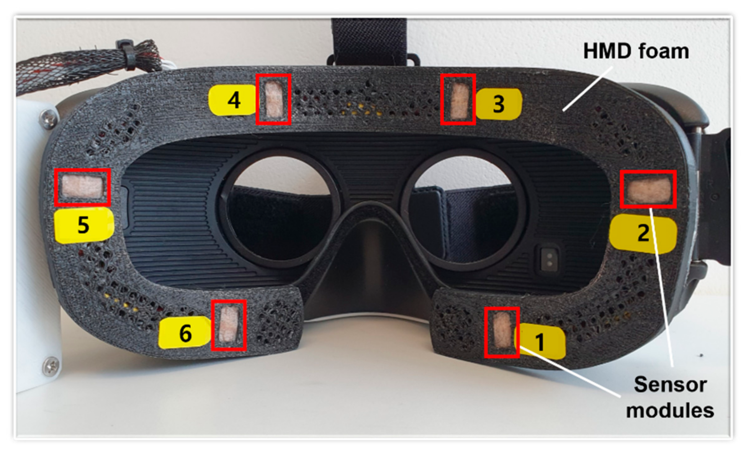
2.1. Apparatus
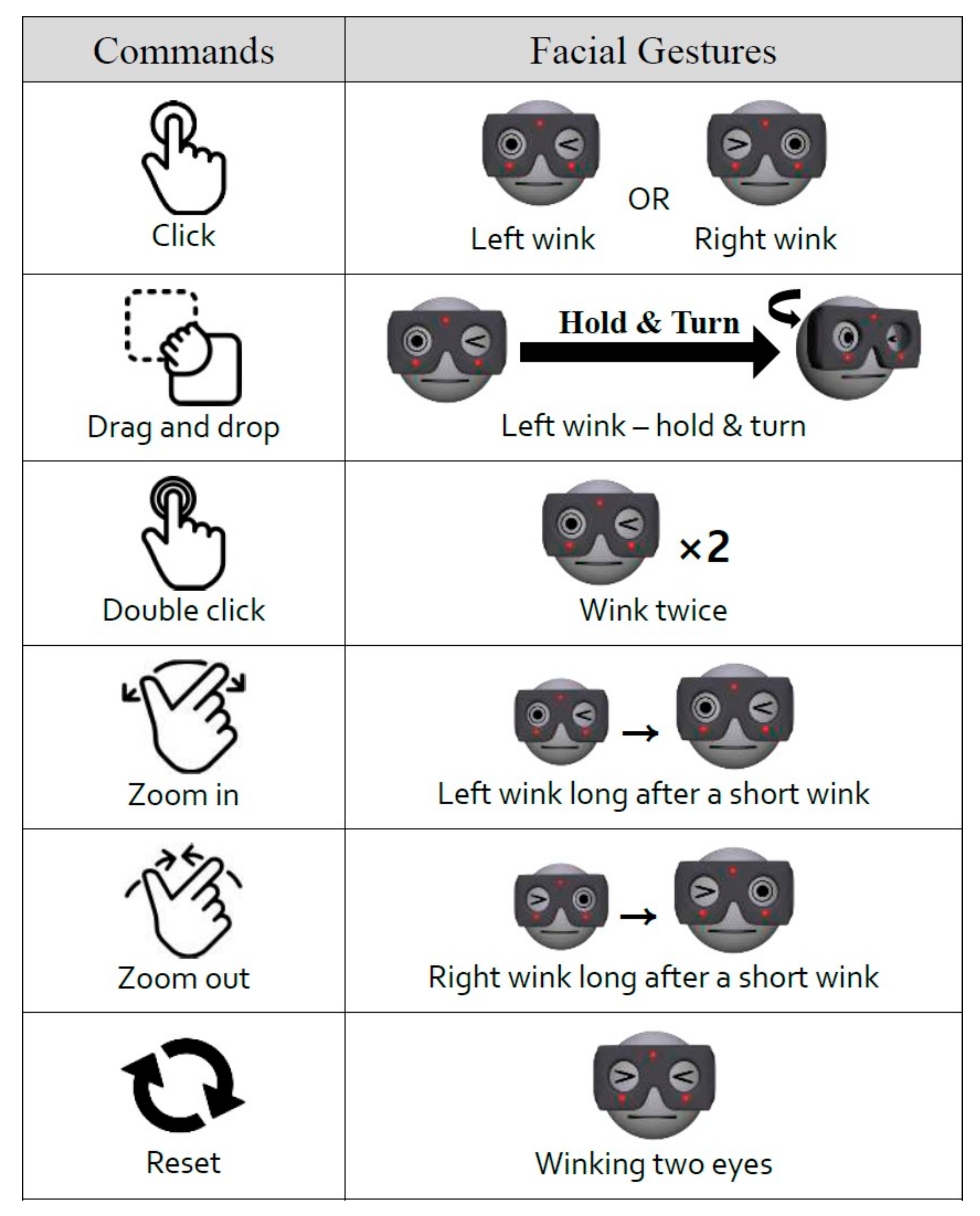
2.2. Command Set
2.3. Experimental Setup and Sensor Data Collection
- (1)
- We tested the recognition rate of each command from four participants. In this intensive test, each participant conducted each command 100 times in succession, and we counted the command inputs received from the interface unit.
- (2)
- A user applicability test for 20 participants differed from test 1. In this test, each user randomly performed each command listed in Figure 4 twenty times and counted the number of command inputs received from the interface device.
- (3)
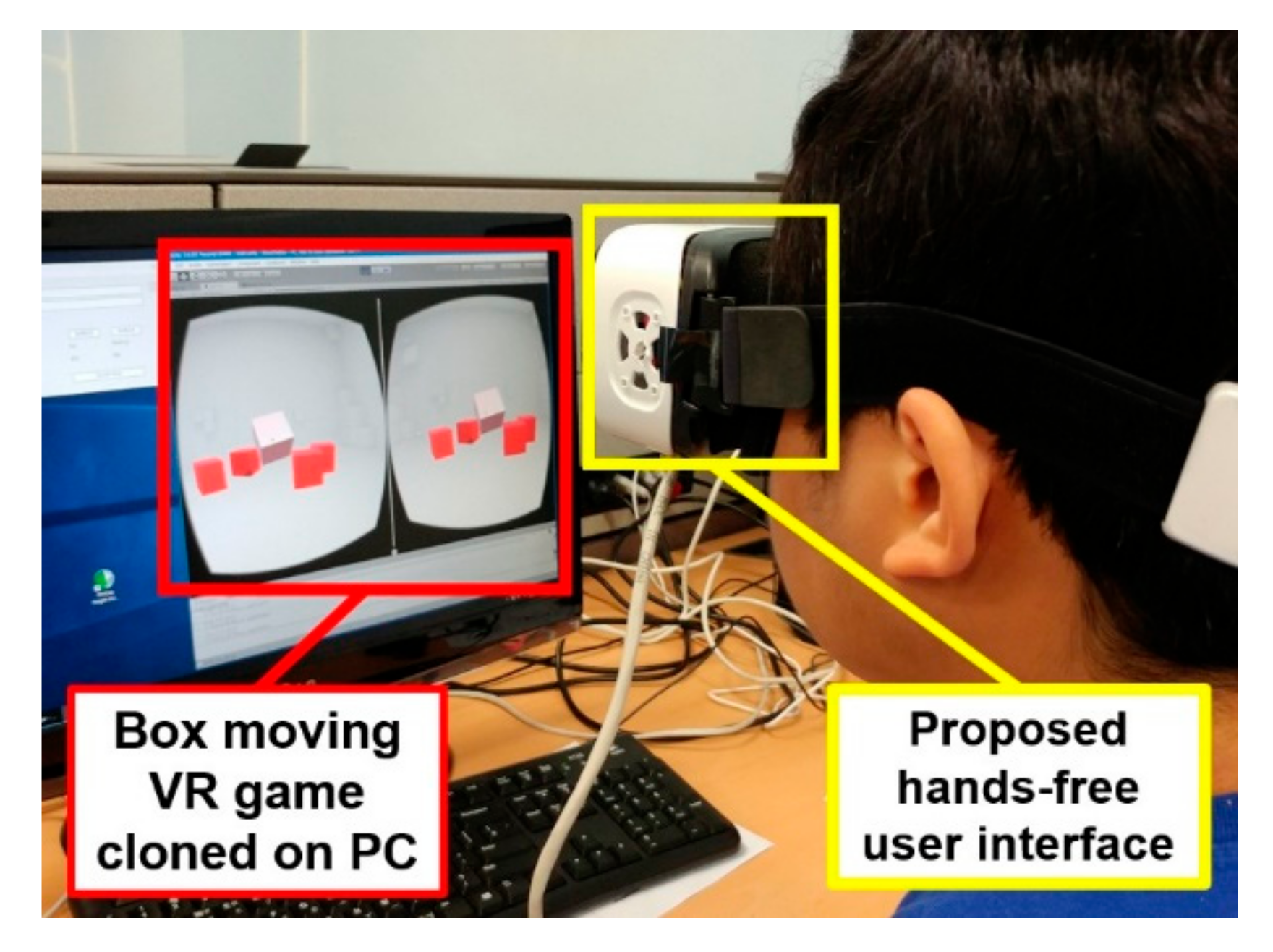
- A usability test was conducted at an exhibition of Information and Communications Technology Forum Korea, (information of the exhibition can be found at the link: https://www.youtube.com/watch?v=8UkGFqAehDI) for more than 100 random visitors, who participated during the exhibition of ICT Forum Korea. The visitors played “move the box” game using prototype VR headset shown in Figure 3. We monitored user feedback on fatigue and inconvenience when playing a game using the prototype VR headset.
3. Measurements and Results
3.1. Physical Layer for Data Acquisition
3.2. Sensor Data Analysis
3.3. Robustness and Reproducibility of the Proposed Sensing Interface
4. Application to Experimental VR Game
5. Discussion
- (Q1)
- VR devices may cause motion sickness to users. In your experience, how much did you feel or agree that the headset with facial gesture UI accelerate your motion sickness during experiments compared to conventional HMDs? Please select from 0 (None) to 5 point (Very severely).
- (Q2)
- About the convenience of the user interface, how did you feel while experimenting with the ease of operation? Please select from 0 (Very easy to control) to 5 point (Very difficult to control).
6. Conclusions
Author Contributions
Funding
Conflicts of Interest
References
- Tung, Y.C.; Hsu, C.Y.; Wang, H.Y.; Chyou, S.; Lin, J.W.; Wu, P.J.; Valstar, A.; Chen, M.Y. User-defined game input for smart glasses in public space. In Proceedings of the 33rd Annual ACM Conference on Human Factors in Computing Systems, Seoul, Korea, 18–23 April 2015; pp. 3327–3336. [Google Scholar]
- Lee, L.H.; Hui, P. Interaction methods for smart glasses: A survey. IEEE Access 2018, 6, 28712–28732. [Google Scholar]
- Samadiani, N.; Huang, G.; Cai, B.; Luo, W.; Chi, C.H.; Xiang, Y.; He, J. A review on automatic facial expression recognition systems assisted by multimodal sensor data. Sensors 2019, 19, 1863. [Google Scholar] [CrossRef] [PubMed] [Green Version]
- Hickson, S.; Dufour, N.; Sud, A.; Kwatra, V.; Essa, I. Eyemotion: Classifying facial expressions in VR using eye-tracking cameras. In Proceedings of the 2019 IEEE Winter Conference on Applications of Computer Vision (WACV), Waikoloa Village, HI, USA, 7–11 January 2019; pp. 1626–1635. [Google Scholar]
- Llanes-Jurado, J.; Marín-Morales, J.; Guixeres, J.; Alcañiz, M. Development and calibration of an eye-tracking fixation identification algorithm for immersive virtual reality. Sensors 2020, 20, 4956. [Google Scholar] [CrossRef] [PubMed]
- Alsaeedi, N.; Wloka, D. Real-time eyeblink detector and eye state classifier for Virtual Reality (VR) headsets (Head-Mounted Displays, HMDs). Sensors 2019, 19, 1121. [Google Scholar] [CrossRef] [PubMed] [Green Version]
- Li, B.; Fu, H.; Wen, D.; Lo, W. Etracker: A mobile gaze-tracking system with near-eye display based on a combined gaze-tracking algorithm. Sensors 2018, 18, 1626. [Google Scholar] [CrossRef] [PubMed] [Green Version]
- Lee, K.-F.; Chen, Y.-L.; Yu, C.-W.; Chin, K.-Y.; Wu, C.-H. Gaze Tracking and Point Estimation Using Low-Cost Head-Mounted Devices. Sensors 2020, 20, 1917. [Google Scholar] [CrossRef] [PubMed]
- Chen, W.X.; Cui, X.Y.; Zheng, J.; Zhang, J.M.; Chen, S.; Yao, Y.D. Gaze Gestures and Their Applications in human-computer interaction with a head-mounted display. arXiv 2019, arXiv:1910.07428. [Google Scholar]
- Memo, A.; Zanuttigh, P. Head-mounted gesture controlled interface for human-computer interaction. Multimed. Tools. Appl. 2018, 77, 27–53. [Google Scholar] [CrossRef]
- Xiao, R.; Schwarz, J.; Throm, N.; Wilson, A.D.; Benko, H. MRTouch: Adding touch input to head-mounted mixed reality. IEEE Trans. Vis. Graph. 2018, 24, 1653–1660. [Google Scholar] [CrossRef] [PubMed]
- Xu, W.; Liang, H.N.; Zhao, Y.; Yu, D.; Monteiro, D. DMove: Directional motion-based interaction for augmented reality head-mounted displays. In Proceedings of the 2019 CHI Conference on Human Factors in Computing Systems, Glasgow, UK, 4–9 May 2019; pp. 1–14. [Google Scholar]
- Yoshioka, T.; Ito, N.; Delcroix, M.; Ogawa, A.; Kinoshita, K.; Fujimoto, M.; Yu, C.; Fabian, J.W.; Espi, M.; Higuchi, T.; et al. The NTT CHiME-3 system: Advances in speech enhancement and recognition for mobile multi-microphone devices. In Proceedings of the 2015 IEEE Workshop on Automatic Speech Recognition and Understanding (ASRU), Scottsdale, AZ, USA, 13–18 December 2015; pp. 436–443. [Google Scholar]
- McGraw, I.; Prabhavalkar, R.; Alvarez, R.; Arenas, M.G.; Rao, K.; Rybach, D.; Alsharif, O.; Sak, H.; Gruenstein, A.; Beaufays, F.; et al. Personalized speech recognition on mobile devices. In Proceedings of the 2016 IEEE International Conference on Acoustics, Speech and Signal Processing (ICASSP), Shanghai, China, 20–25 March 2016; pp. 5955–5959. [Google Scholar]
- Li, H.; Trutoiu, L.; Olszewski, K.; Wei, L.; Trutna, T.; Hsieh, P.L.; Nicholls, A.; Ma, C. Facial performance sensing head-mounted display. ACM Trans. Graphics (ToG) 2015, 34, 1–9. [Google Scholar] [CrossRef] [Green Version]
- Cha, J.; Kim, J.; Kim, S. Hands-free user interface for AR/VR devices exploiting wearer’s facial gestures using unsupervised deep learning. Sensors 2019, 19, 4441. [Google Scholar] [CrossRef] [PubMed] [Green Version]
- Kim, J.; Cha, J.; Lee, H.; Kim, S. Hand-free natural user interface for VR HMD with IR based facial gesture tracking sensor. In Proceedings of the 23rd ACM Symposium on Virtual Reality Software and Technology, New York, NY, USA, 8–10 November 2017; pp. 1–2. [Google Scholar]
- Hennelly, S. Text Selection Using HMD Head-Tracker and Voice-Command. U.S. Patent 9,383,816, 5 July 2016. [Google Scholar]
- Cha, J.; Kim, J.; Kim, S. An IR-based facial expression tracking sensor for head-mounted displays. In Proceedings of the 2016 IEEE SENSORS, Orlando, FL, USA, 30 October–3 November 2016; pp. 1–3. [Google Scholar]
- Shiho, K.; Jaekwang, C. Method for Recognizing Facial Expression of Headset Wearing User and Apparatus Enabling the Same. U.S. Patent 10,248,852, 2 April 2019. [Google Scholar]
- Shiho, K.; Jaekwang, C. Device for Recognizing Facial Expression and Method Thereof. U.S. Patent 10,614,295, 7 April 2020. [Google Scholar]
- Cha, J.; Kim, J.; Kim, S. Noninvasive determination of fiber orientation and tracking 2-dimensional deformation of human skin utilizing spatially resolved reflectance of infrared light measurement in vivo. Measurement 2019, 142, 170–180. [Google Scholar] [CrossRef]
- Friesen, E.; Ekman, P. Facial Action Coding System: A Technique for the Measurement of Facial Movement; Consulting Psychologists Press: City of Palo Alto, CA, USA, 1978. [Google Scholar]
- Frigerio, A.; Cavallari, P.; Frigeni, M.; Pedrocchi, A.; Sarasola, A.; Ferrante, S. Surface electromyographic mapping of the orbicularis oculi muscle for real-time blink detection. JAMA Facial Plast. Surg. 2014, 16, 335–342. [Google Scholar] [CrossRef] [PubMed] [Green Version]
- International Electrotechnical Commission. IEC 62471: 2006 Photobiological safety of lamps and lampsystems. In International Standard; International Electrotechnical Commission: Geneva, Switzerland, 2006. [Google Scholar]
- Lee, S.; Ha, G.; Cha, J.; Kim, J.; Lee, H.; Kim, S. CyberTouch-touch and cursor interface for VR HMD. In International Conference on Human-Computer Interaction; Springer: Berlin/Heidelberg, Germany, 2015; pp. 503–507. [Google Scholar]


| Modality | Methods | Devices | Accuracy (Mean, %) | Refs |
|---|---|---|---|---|
| Gaze tracking | Combines traditional gaze-tracking algorithm with geometric model-based convolutional neural network | Eye glass with near-eye viewing device | 98.0 | [7], 2019 |
| Gaze tracking | Adds extracted feature layers on different receptive fields on top of full preactivation ResNet | Head-mounted display | 96.7 | [9], 2019 |
| Hand gestures | Real-time gesture recognition exploiting feature descriptors arranged in a multidimensional structure | Head-mounted display | 90.0 | [10], 2018 |
| Hand gestures | Combines depth and infrared camera streams to enable robust finger-tracking | Head-mounted MR device | 96.5 | [11], 2018 |
| Hand/hybrid gesture with body motion | Combines motion-based interaction with hand/hybrid gestures for detailed menu selection | Head-mounted AR device | 98.1 | [12], 2019 |
| Voice recognition | Acoustic model for multi-microphone environment based on the network in network concept with minimum variance distortionless response beamformer for noise reduction | Mobile device | 94.2 | [13], 2015 |
| Voice recognition | Implements large vocational speech recognition system with small memory, which can be mounted on mobile devices | Mobile device | 86.5 | [14], 2016 |
| Skin movement | Creates 3D face model in head-mounted display (HMD) environment with eight strain gauges and RGB-D camera | Head-mounted display | NA | [15], 2015 |
| Skin movement | IR-based skin deformation detection with a classifier neural network for spatiotemporal data process | AR glass | 95.6 | [16], 2019 |
| Recognition Rate of Each Command (%) | |||||||
|---|---|---|---|---|---|---|---|
| User ID | Click | Drag Drop | Double Click | Zoom in | Zoom out | Reset | Average |
| 1 | 99 | 100 | 98 | 98 | 99 | 100 | 99 |
| 2 | 99 | 100 | 98 | 99 | 99 | 99 | 99 |
| 3 | 100 | 99 | 99 | 100 | 100 | 100 | 99.67 |
| 4 | 99 | 100 | 99 | 99 | 99 | 100 | 99.33 |
| Average | 99.25 | 99.75 | 98.5 | 99 | 99.25 | 99.75 | 99.25 |
Publisher’s Note: MDPI stays neutral with regard to jurisdictional claims in published maps and institutional affiliations. |
© 2020 by the authors. Licensee MDPI, Basel, Switzerland. This article is an open access article distributed under the terms and conditions of the Creative Commons Attribution (CC BY) license (http://creativecommons.org/licenses/by/4.0/).
Share and Cite
Kim, J.; Cha, J.; Kim, S. Hands-Free User Interface for VR Headsets Based on In Situ Facial Gesture Sensing. Sensors 2020, 20, 7206. https://doi.org/10.3390/s20247206
Kim J, Cha J, Kim S. Hands-Free User Interface for VR Headsets Based on In Situ Facial Gesture Sensing. Sensors. 2020; 20(24):7206. https://doi.org/10.3390/s20247206
Chicago/Turabian StyleKim, Jinhyuk, Jaekwang Cha, and Shiho Kim. 2020. "Hands-Free User Interface for VR Headsets Based on In Situ Facial Gesture Sensing" Sensors 20, no. 24: 7206. https://doi.org/10.3390/s20247206