Exploring Fast Fingerprint Construction Algorithm for Unmodulated Visible Light Indoor Localization


Abstract
:1. Introduction
- We proposed a new reverse fingerprint collection method to realize the rapid collection and deployment of fingerprint information with the change of environment. In addition, through theory and practice, we prove the reusability of reverse-collected fingerprints in different environments;
- We combine the theory of light propagation and image processing method for the first time, which significantly reduces the workload and time cost of constructing a visible light location fingerprint database. Meanwhile, the fingerprint library of the whole indoor environment can be obtained in a short time;
- We conducted multiple sets of experiments and compared the impact of fingerprints collected in different environments on the positioning results. The reverse fingerprinting can be achieved. In 95% of cases, the positioning accuracy can be guaranteed to be less than 10 cm.
2. Related Work
3. Position Basics
3.1. Polarization
3.2. Birefringence
3.3. Color Polarization
4. Reverse Fingerprint Position Method
4.1. Reverse Fingerprint
4.2. Position
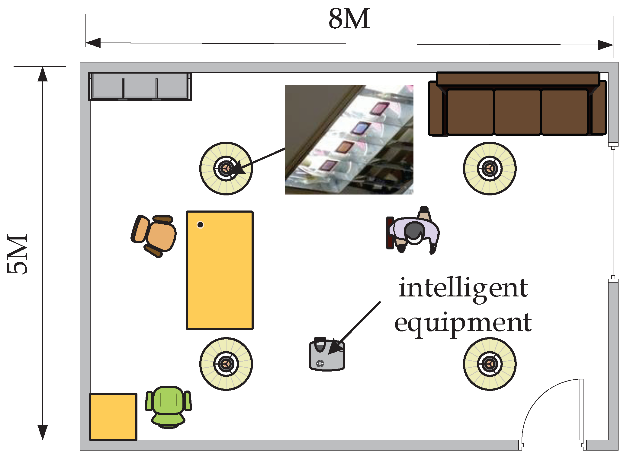
5. Experiment
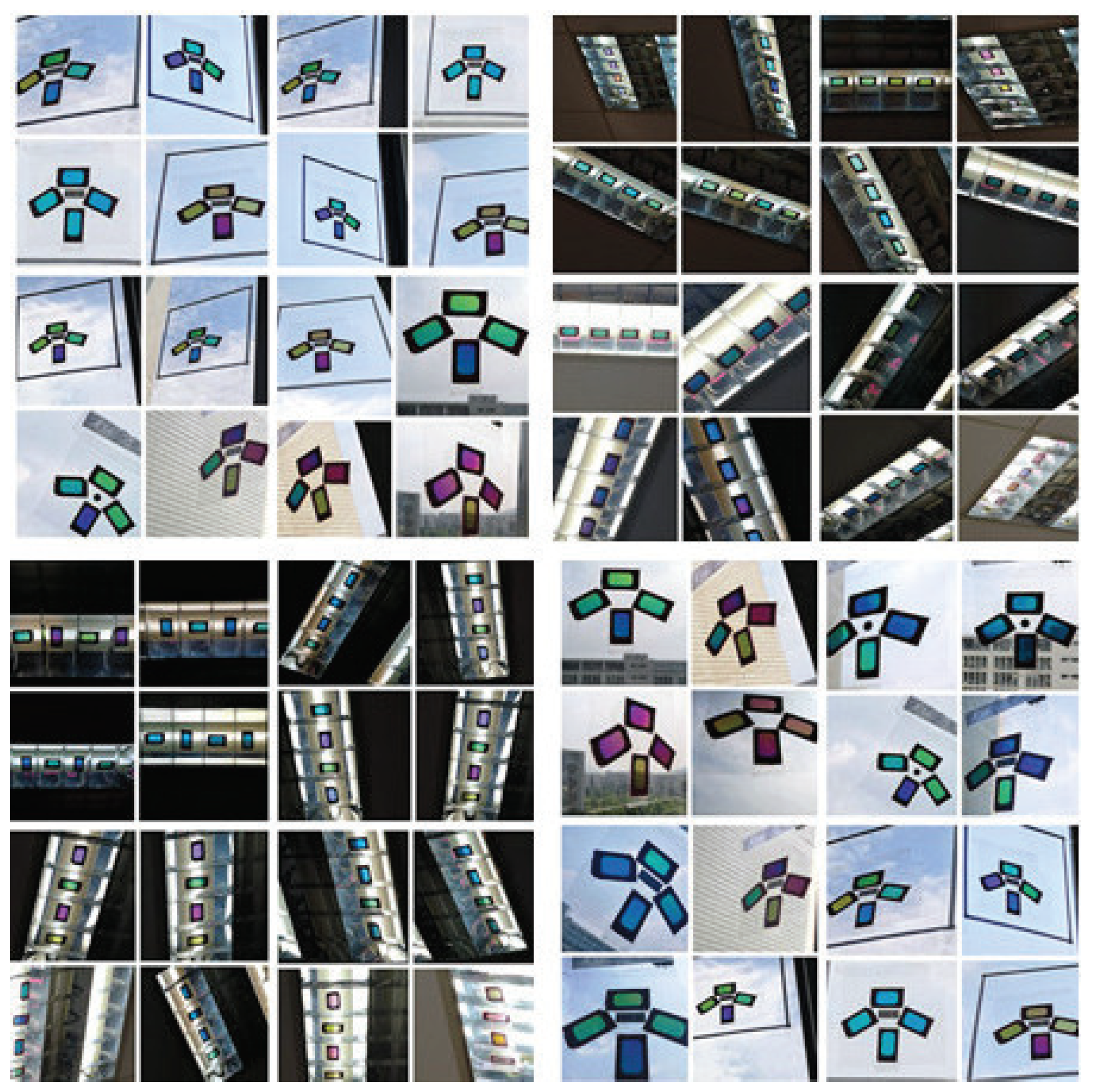
5.1. Collect Reverse Fingerprint
5.2. 3D Localization
6. Evaluation
- The influence of different distances on positioning accuracy;
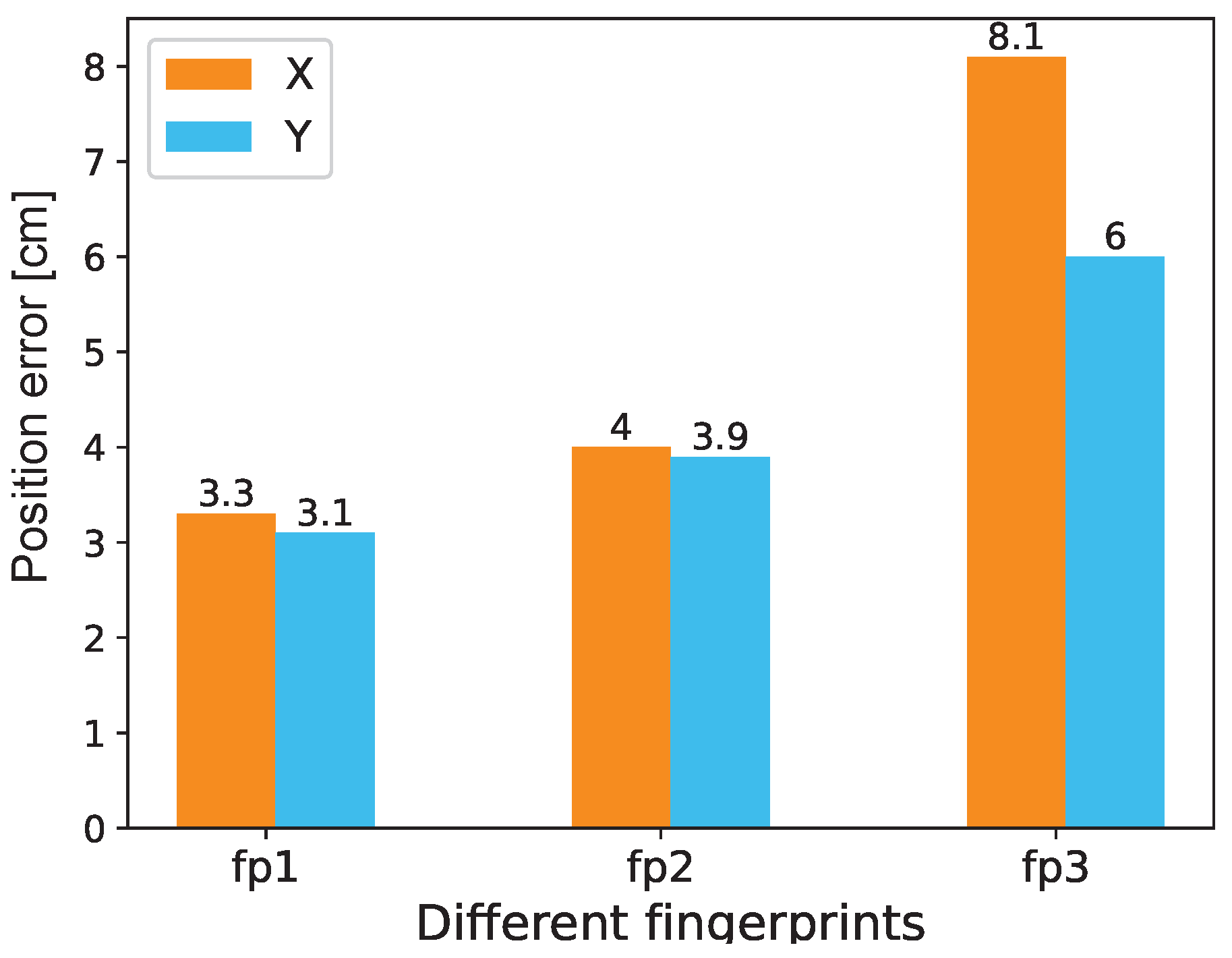
- The influence of fingerprints collected under different lights and distances;
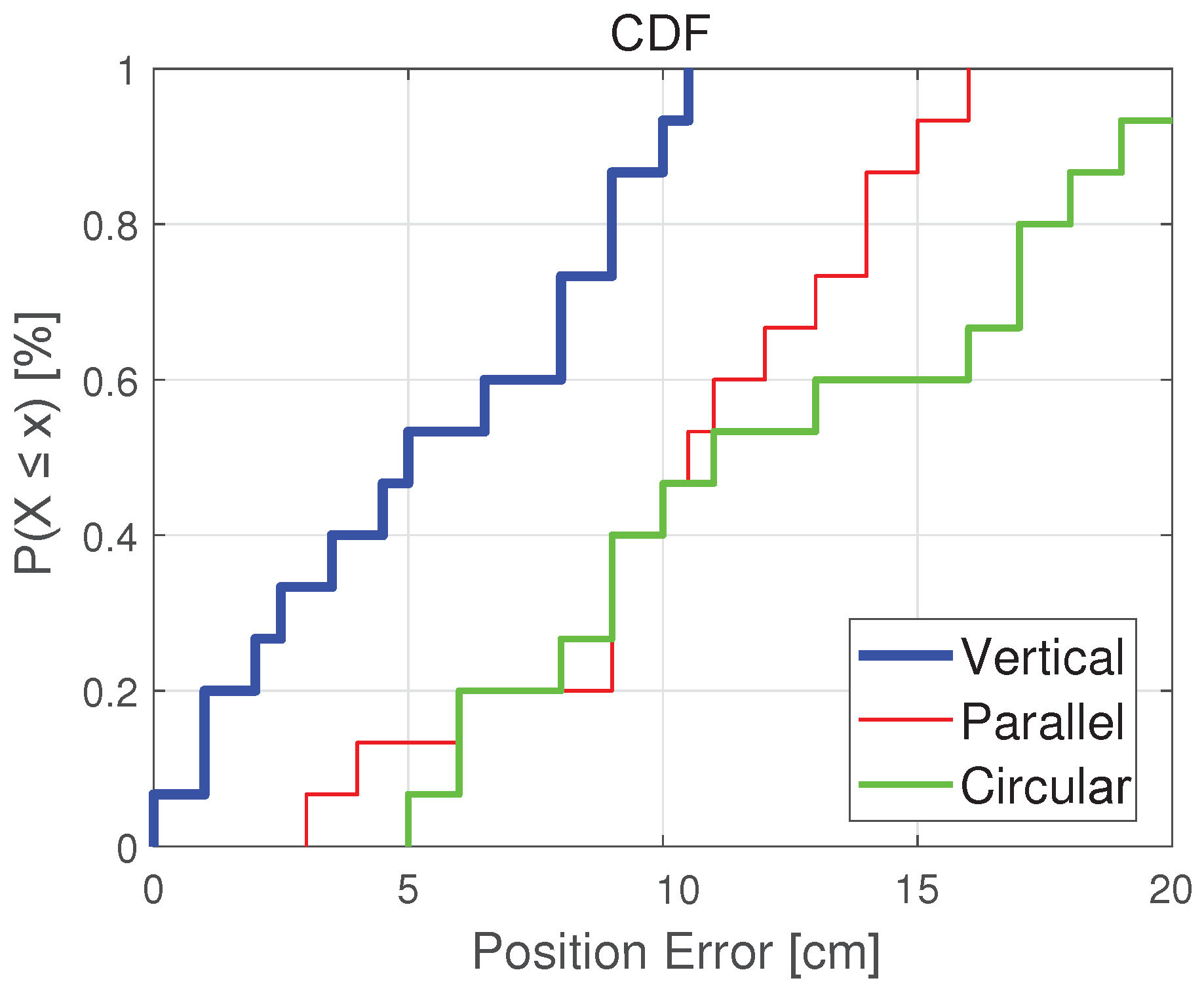
- The effect of different color polarizer placement on the positioning results;
- The influence of different periods of a day on positioning accuracy;
- The influence of the vertical distance between the light source and camera position on positioning accuracy;
- The influence of different pixel camera on positioning accuracy;
- The influence of different ambient light on positioning accuracy.
6.1. Localization Accuracy
6.2. Impact of Different Fingerprints
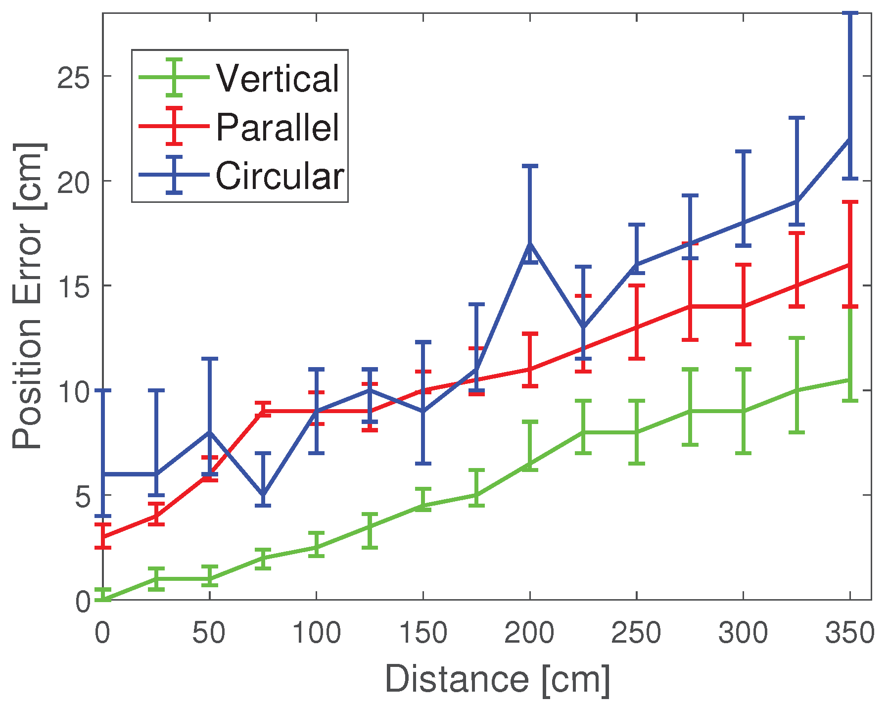
6.3. Impact of Different Color Polarizer Placements
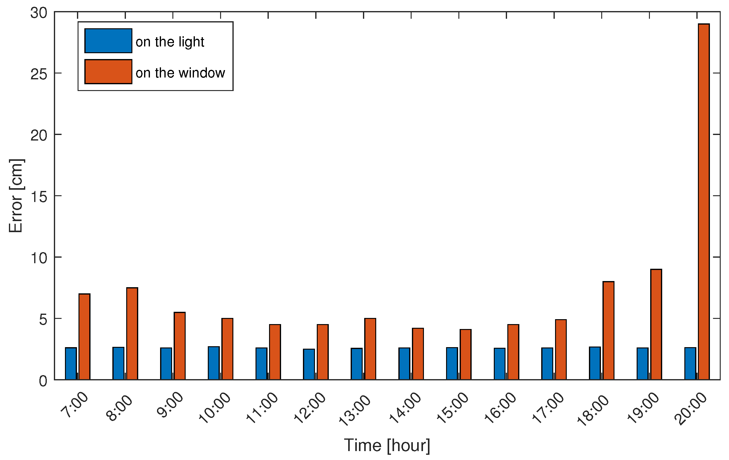
6.4. Influence of Different Time Periods of a Day
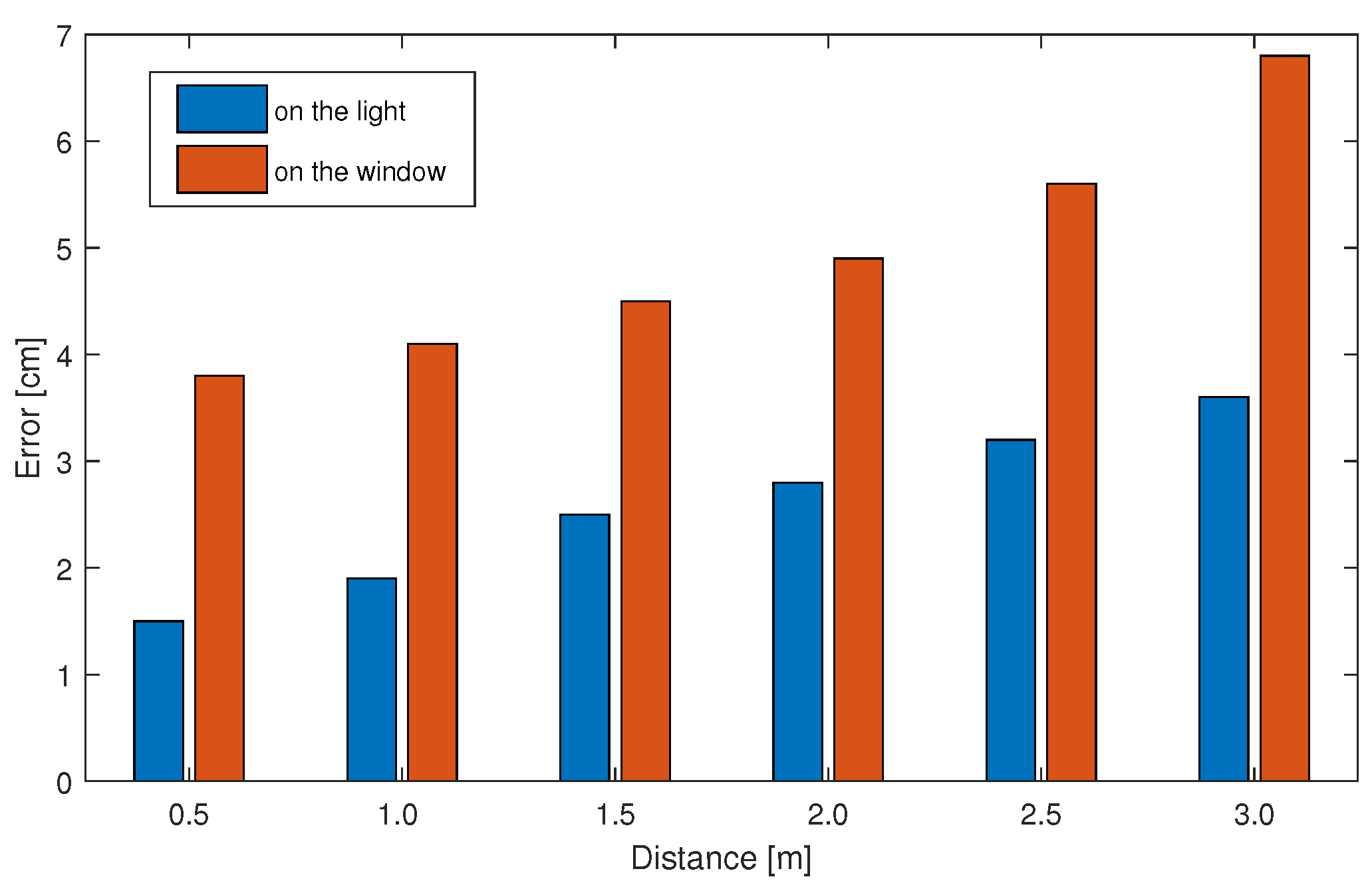
6.5. Influence of Vertical Distance between Light Source and Camera Position
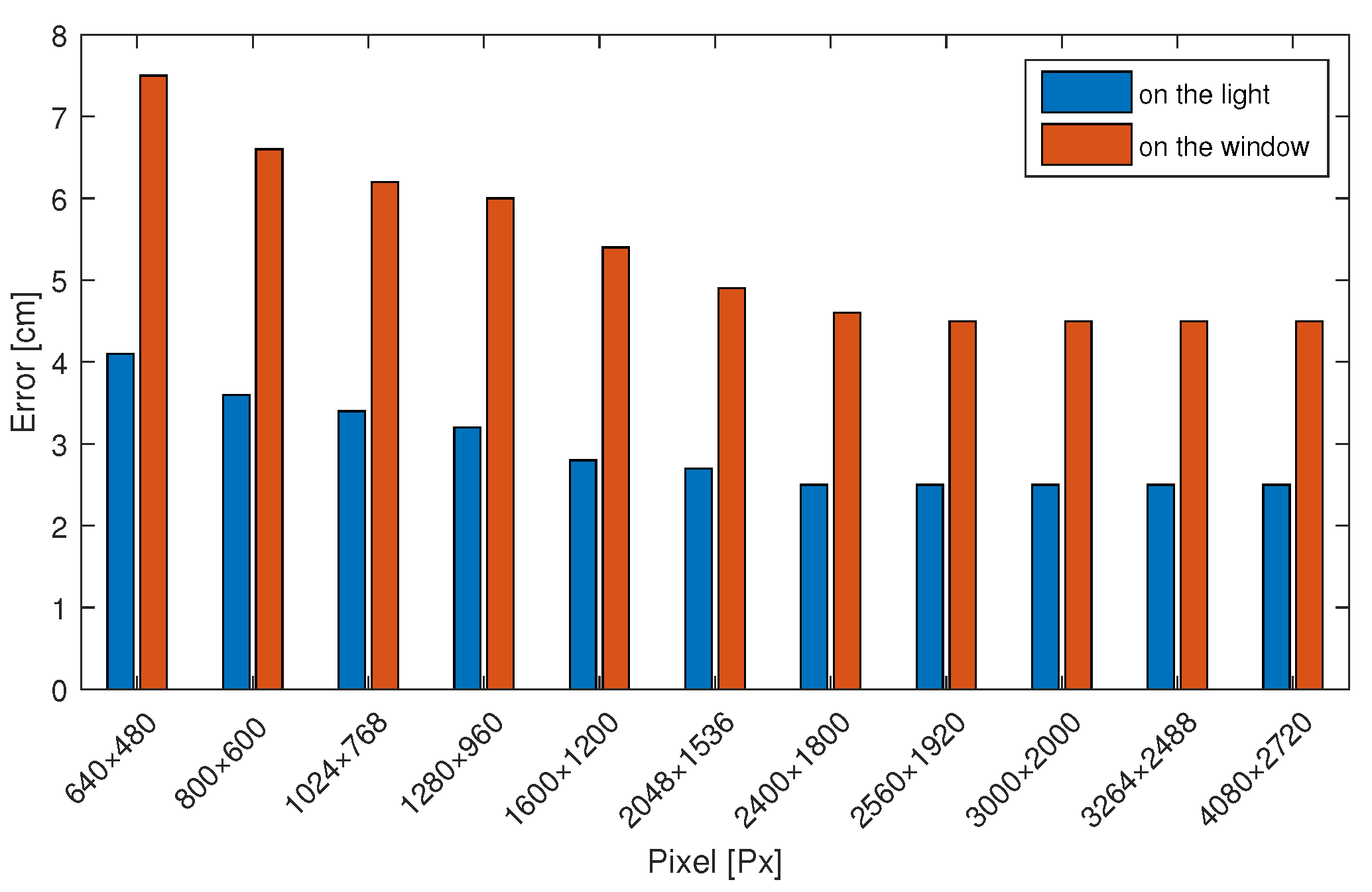
6.6. Impact of Different Pixel Camera
6.7. Impact of Different Ambient Light
7. Conclusions
Author Contributions
Funding
Acknowledgments
Conflicts of Interest
References
- Torres, J.C.; Montes, A.; Mendoza, S.L.; Fernandez, P.R.; Betancourt, J.S.; Escandell, L.; del Valle, C.I.; Sanchez-Pena, J.M. A Low-Cost Visible Light Positioning System for Indoor Positioning. Sensors 2020, 20, 5145. [Google Scholar] [CrossRef] [PubMed]
- Chen, G.; Chen, W.; Yang, Q.; Xu, Z.; Yang, L.; Conradt, J.; Knoll, A. A Novel Visible Light Positioning System With Event-Based Neuromorphic Vision Sensor. IEEE Sens. J. 2020, 20, 10211–10219. [Google Scholar] [CrossRef]
- Knudde, N.; Raes, W.; De Bruycker, J.; Dhaene, T.; Stevens, N. Data-Efficient Gaussian Process Regression for Accurate Visible Light Positioning. IEEE Commun. Lett. 2020, 24, 1705–1709. [Google Scholar] [CrossRef]
- Wu, H.; Wang, Q.; Xiong, J.; Zuniga, M. SmartVLC: Co-Designing Smart Lighting and Communication for Visible Light Networks. IEEE Trans. Mob. Comput. 2020, 19, 1956–1970. [Google Scholar] [CrossRef]
- Aparicio-Esteve, E.; Hernandez, A.; Urena, J.; Villadangos, J.M. Visible Light Positioning System Based on a Quadrant Photodiode and Encoding Techniques. IEEE Trans. Instrum. Meas. 2020, 69, 5589–5603. [Google Scholar] [CrossRef]
- Zhou, B.; Liu, A.; Lau, V. Visible Light-Based User Position, Orientation and Channel Estimation Using Self-Adaptive Location-Domain Grid Sampling. IEEE Trans. Wirel. Commun. 2020, 19, 5025–5039. [Google Scholar] [CrossRef]
- Hong, C.Y.; Wu, Y.C.; Liu, Y.; Chow, C.W.; Yeh, C.H.; Hsu, K.L.; Lin, D.C.; Liao, X.L.; Lin, K.H.; Chen, Y.Y. Angle-of-Arrival (AOA) Visible Light Positioning (VLP) System Using Solar Cells with Third-Order Regression and Ridge Regression Algorithms. IEEE Photonics J. 2020, 12. [Google Scholar] [CrossRef]
- De-La-Llana-Calvo, A.; Lazaro-Galilea, J.L.; Gardel-Vicente, A.; Rodriguez-Navarro, D.; Rubiano-Muriel, B.; Bravo-Munoz, I. Analysis of Multiple-Access Discrimination Techniques for the Development of a PSD-Based VLP System. Sensors 2020, 20, 1717. [Google Scholar] [CrossRef] [Green Version]
- Li, L.; Xie, P.; Wang, J.; Acm. RainbowLight: Towards Low Cost Ambient Light Positioning with Mobile Phones. In Proceedings of the Mobicom’18, 24th Annual International Conference on Mobile Computing and Networking, New Delhi, India, 29 October–2 November 2018; pp. 445–457. [Google Scholar] [CrossRef]
- Keskin, M.F.; Sezer, A.D.; Gezici, S. Localization via Visible Light Systems. Proc. IEEE 2018, 106, 1063–1088. [Google Scholar] [CrossRef] [Green Version]
- Lee, Y.U.; Park, S.H. Short-range Visible Light Positioning Based on Angle of Arrival for Smart Indoor Service. J. Electr. Eng. Technol. 2018, 13, 1363–1370. [Google Scholar] [CrossRef]
- Chen, H.; Guan, W.; Li, S.; Wu, Y. Indoor high precision three-dimensional positioning system based on visible light communication using modified genetic algorithm. Opt. Commun. 2018, 413, 103–120. [Google Scholar] [CrossRef]
- Xie, C.; Guan, W.; Wu, Y.; Fang, L.; Cai, Y. The LED-ID Detection and Recognition Method Based on Visible Light Positioning Using Proximity Method. IEEE Photonics J. 2018, 10. [Google Scholar] [CrossRef]
- Lin, X.; Zhang, L. Intelligent and Practical Deep Learning Aided Positioning Design for Visible Light Communication Receivers. IEEE Commun. Lett. 2020, 24, 577–580. [Google Scholar] [CrossRef]
- Soto, I.; Nilson Rodrigues, R.; Massuyama, G.; Seguel, F.; Palacios Jativa, P.; Azurdia-Meza, C.A.; Krommenacker, N. A Hybrid VLC-RF Portable Phasor Measurement Unit for Deep Tunnels. Sensors 2020, 20, 790. [Google Scholar] [CrossRef] [Green Version]
- Konings, D.; Faulkner, N.; Alam, F.; Lai, E.M.K.; Demidenko, S. FieldLight: Device-Free Indoor Human Localization Using Passive Visible Light Positioning and Artificial Potential Fields. IEEE Sens. J. 2020, 20, 1054–1066. [Google Scholar] [CrossRef]
- Wu, Y.; Liu, X.; Guan, W.; Chen, B.; Chen, X.; Xie, C. High-speed 3D indoor localization system based on visible light communication using differential evolution algorithm. Opt. Commun. 2018, 424, 177–189. [Google Scholar] [CrossRef]
- Vieira, M.; Vieira, M.A.; Louro, P.; Vieira, P. Light-emitting diodes aided indoor localization using visible light communication technology. Opt. Eng. 2018, 57. [Google Scholar] [CrossRef]
- Li, Y.; Ghassemlooy, Z.; Tang, X.; Lin, B.; Zhang, Y. A VLC Smartphone Camera Based Indoor Positioning System. IEEE Photonics Technol. Lett. 2018, 30, 1171–1174. [Google Scholar] [CrossRef]
- Amsters, R.; Demeester, E.; Stevens, N.; Slaets, P. In-Depth Analysis of Unmodulated Visible Light Positioning Using the Iterated Extended Kalman Filter. Sensors 2019, 19, 5198. [Google Scholar] [CrossRef] [Green Version]
- Almadani, Y.; Ijaz, M.; Joseph, W.; Bastiaens, S.; Rajbhandari, S.; Adebisi, B.; Plets, D. A Novel 3D Visible Light Positioning Method Using Received Signal Strength for Industrial Applications. Electronics 2019, 8, 1311. [Google Scholar] [CrossRef] [Green Version]
- Yang, F.; Gao, J.; Liu, Y. Indoor visible light positioning system based on cooperative localization. Opt. Eng. 2019, 58. [Google Scholar] [CrossRef] [Green Version]
- Tran, H.Q.; Ha, C. Fingerprint-Based Indoor Positioning System Using Visible Light Communication—A Novel Method for Multipath Reflections. Electronics 2019, 8, 63. [Google Scholar] [CrossRef] [Green Version]
- Keskin, M.F.; Sezer, A.D.; Gezici, S. Optimal and Robust Power Allocation for Visible Light Positioning Systems Under Illumination Constraints. IEEE Trans. Commun. 2019, 67, 527–542. [Google Scholar] [CrossRef]
- Hao, J.; Chen, J.; Wang, R. Visible Light Positioning Using A Single LED Luminaire. IEEE Photonics J. 2019, 11. [Google Scholar] [CrossRef]
- Gong, C. Visible Light Communication and Positioning: Present and Future. Electronics 2019, 8, 788. [Google Scholar] [CrossRef] [Green Version]
- Xu, J.; Gong, C.; Xu, Z. Experimental Indoor Visible Light Positioning Systems With Centimeter Accuracy Based on a Commercial Smartphone Camera. IEEE Photonics J. 2018, 10. [Google Scholar] [CrossRef]
- Stevens, N.; Steendam, H. Magnitude of the Distance Estimation Bias in Received Signal Strength Visible Light Positioning. IEEE Commun. Lett. 2018, 22, 2250–2253. [Google Scholar] [CrossRef]
- Gligoric, K.; Ajmani, M.; Vukobratovic, D.; Sinanovic, S. Visible Light Communications-Based Indoor Positioning via Compressed Sensing. IEEE Commun. Lett. 2018, 22, 1410–1413. [Google Scholar] [CrossRef] [Green Version]
- Phong Ha, N.; Arsalan, M.; Koo, J.H.; Naqvi, R.A.; Noi Quang, T.; Park, K.R. LightDenseYOLO: A Fast and Accurate Marker Tracker for Autonomous UAV Landing by Visible Light Camera Sensor on Drone. Sensors 2018, 18, 1703. [Google Scholar] [CrossRef] [Green Version]
- Prince, G.B.; Little, T.D.C. Two-Phase Framework for Indoor Positioning Systems Using Visible Light. Sensors 2018, 18, 1917. [Google Scholar] [CrossRef] [Green Version]
- Guan, W.; Chen, X.; Huang, M.; Liu, Z.; Wu, Y.; Chen, Y. High-Speed Robust Dynamic Positioning and Tracking Method Based on Visual Visible Light Communication Using Optical Flow Detection and Bayesian Forecast. IEEE Photonics J. 2018, 10. [Google Scholar] [CrossRef]
- Zhao, H.X.; Wang, J.T. A Novel Three-Dimensional Algorithm Based on Practical Indoor Visible Light Positioning. IEEE Photonics J. 2019, 11. [Google Scholar] [CrossRef]
- Chuang, Y.C.; Li, Z.Q.; Hsu, C.W.; Liu, Y.; Chow, C.W. Visible light communication and positioning using positioning cells and machine learning algorithms. Opt. Express 2019, 27, 16377–16383. [Google Scholar] [CrossRef]
- Afzalan, M.; Jazizadeh, F. Indoor Positioning Based on Visible Light Communication: A Performance-based Survey of Real-world Prototypes. Acm Comput. Surv. 2019, 52. [Google Scholar] [CrossRef]
- Huang, H.; Lin, B.; Feng, L.; Lv, H. Hybrid indoor localization scheme with image sensor-based visible light positioning and pedestrian dead reckoning. Appl. Opt. 2019, 58, 3214–3221. [Google Scholar] [CrossRef]
- Yuan, T.; Xu, Y.; Wang, Y.; Han, P.; Chen, J. A Tilt Receiver Correction Method for Visible Light Positioning Using Machine Learning Method. IEEE Photonics J. 2018, 10. [Google Scholar] [CrossRef]
- Tran, H.Q.; Ha, C. Improved Visible Light-Based Indoor Positioning System Using Machine Learning Classification and Regression. Appl. Sci. 2019, 9, 1048. [Google Scholar] [CrossRef] [Green Version]
- Wu, Y.; Guo, Z.; Liu, X.; Xian, Y.; Guan, W. High precision and high speed of three-dimensional indoor localization system based on visible light communication using improved bacterial colony chemotaxis algorithm. Opt. Eng. 2019, 58. [Google Scholar] [CrossRef]
- Xie, Z.; Guan, W.; Zheng, J.; Zhang, X.; Chen, S.; Chen, B. A High-Precision, Real-Time, and Robust Indoor Visible Light Positioning Method Based on Mean Shift Algorithm and Unscented Kalman Filter. Sensors 2019, 19, 1094. [Google Scholar] [CrossRef] [Green Version]
- Kho, A.; Srinivasan, V.J. Compensating spatially dependent dispersion in visible light OCT. Opt. Lett. 2019, 44, 775–778. [Google Scholar] [CrossRef]
- Cincotta, S.; He, C.; Neild, A.; Armstrong, J. Indoor Visible Light Positioning: Overcoming the Practical Limitations of the Quadrant Angular Diversity Aperture Receiver (QADA) by Using the Two-Stage QADA-Plus Receiver. Sensors 2019, 19, 956. [Google Scholar] [CrossRef] [PubMed] [Green Version]
- De-La-Llana-Calvo, A.; Lazaro-Galilea, J.L.; Gardel-Vicente, A.; Rodriguez-Navarro, D.; Bravo-Munoz, I.; Espinosa-Zapata, F. Characterization of Multipath Effects in Indoor Positioning Systems by AoA and PoA Based on Optical Signals. Sensors 2019, 19, 917. [Google Scholar] [CrossRef] [PubMed] [Green Version]
- Guan, W.; Wen, S.; Liu, L.; Zhang, H. High-precision indoor positioning algorithm based on visible light communication using complementary metal-oxide-semiconductor image sensor. Opt. Eng. 2019, 58. [Google Scholar] [CrossRef]
- Guo, C.; Shao, J. Implementation and improvement of Bayes’s theorem for indoor visible light positioning system. Opt. Eng. 2019, 58. [Google Scholar] [CrossRef]
- Qin, C.; Zhan, X. VLIP: Tightly Coupled Visible-Light/Inertial Positioning System to Cope With Intermittent Outage. IEEE Photonics Technol. Lett. 2019, 31, 129–132. [Google Scholar] [CrossRef]
- Du, P.; Zhang, S.; Chen, C.; Yang, H.; Zhong, W.D.; Zhang, R.; Alphones, A.; Yang, Y. Experimental Demonstration of 3D Visible Light Positioning Using Received Signal Strength with Low-Complexity Trilateration Assisted by Deep Learning Technique. IEEE Access 2019, 7, 93986–93997. [Google Scholar] [CrossRef]
- Zhang, Z.; Chen, H.; Hong, X.; Chen, J.; IEEE. Accuracy Enhancement of Indoor Visible Light Positioning using Point-Wise Reinforcement Learning. In Proceedings of the Optical Fiber Communications Conference, San Diego, CA, USA, 3–7 March 2019. [Google Scholar]
- Li, N.; Qiao, Y.; Zhang, T.; Lu, Y. Dead-zone-free three-dimensional indoor positioning method based on visible light communication with dimensionality reduction algorithm. Opt. Eng. 2018, 57. [Google Scholar] [CrossRef]
- Wang, Q.; Luo, H.; Men, A.; Zhao, F.; Gao, X.; Wei, J.; Zhang, Y.; Huang, Y. Light positioning: A high-accuracy visible light indoor positioning system based on attitude identification and propagation model. Int. J. Distrib. Sens. Netw. 2018, 14. [Google Scholar] [CrossRef] [Green Version]


| Environment | Photo | Mean Error |
|---|---|---|
| Natural Light |  | 25.45 cm |
| W/ Luminaires | 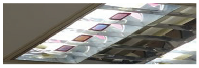 | 7.79 cm |
| W/O Luminaires | 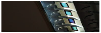 | 3.3 cm |
Publisher’s Note: MDPI stays neutral with regard to jurisdictional claims in published maps and institutional affiliations. |
© 2020 by the authors. Licensee MDPI, Basel, Switzerland. This article is an open access article distributed under the terms and conditions of the Creative Commons Attribution (CC BY) license (http://creativecommons.org/licenses/by/4.0/).
Share and Cite
Shi, C.; Niu, X.; Li, T.; Li, S.; Huang, C.; Niu, Q. Exploring Fast Fingerprint Construction Algorithm for Unmodulated Visible Light Indoor Localization. Sensors 2020, 20, 7245. https://doi.org/10.3390/s20247245
Shi C, Niu X, Li T, Li S, Huang C, Niu Q. Exploring Fast Fingerprint Construction Algorithm for Unmodulated Visible Light Indoor Localization. Sensors. 2020; 20(24):7245. https://doi.org/10.3390/s20247245
Chicago/Turabian StyleShi, Chenqi, Xinyv Niu, Tao Li, Sen Li, Chanjuan Huang, and Qiang Niu. 2020. "Exploring Fast Fingerprint Construction Algorithm for Unmodulated Visible Light Indoor Localization" Sensors 20, no. 24: 7245. https://doi.org/10.3390/s20247245