Enhanced Quarter Spherical Acoustic Energy Harvester Based on Dual Helmholtz Resonators


Abstract
:1. Introduction
- (1)
- Helmholtz resonators are based on the Helmholtz effect, which can periodically amplify an incident acoustic wave [9,10,11]. Farid Khan et al. proposed an AEH with a tapered Helmholtz resonator, and they improved the output performance by changing the cavity structure. It could receive an output power of 90.6 L μW with an excitation of 130 dB [12]. Xiao Peng et al. designed a coupled AEH, and the output power could be increased by up to 16 times compared with a single resonator [13].
- (2)
- Quarter-wave resonators are optimized based on Helmholtz resonators, and the length of the cavity is equal to a quarter of a wavelength [14]. It can harvest acoustic energy with a smaller volume, which saves space in a particular structure. Bin Li et al. designed an AEH with a quarter-wavelength straight-tube acoustic resonator, and several piezoelectric cantilever beams were placed inside the resonator. The largest sound pressure amplification ratio was about 59.1 at an incident sound of 100 dB [15].
- (3)
- Acoustic crystals use a point defect as a resonator [16]. A point defect in a structure is caused by the removal of a rod from the perfect sonic crystal. It can significantly improve output performance. Liang-Yu Wu et al. designed and put an piezoelectric material in a point defect; their results showed that the acoustic power was about 24.4 times larger than that without a sonic crystal [17].
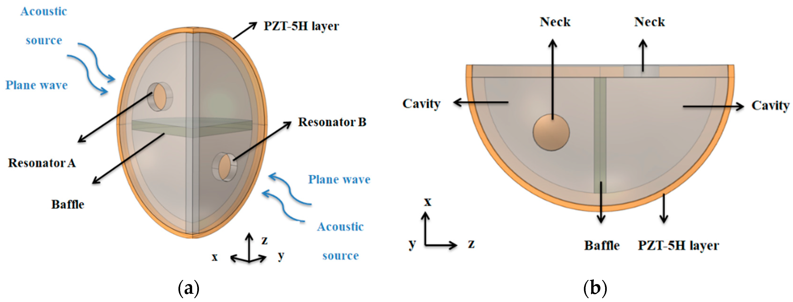
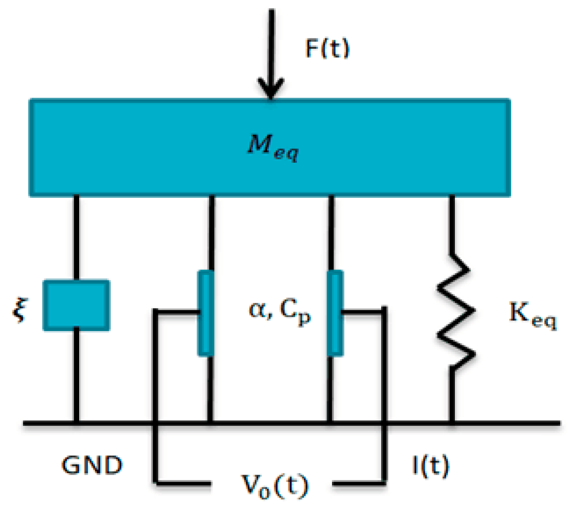
2. Principle and Theory
3. Results and Discussions
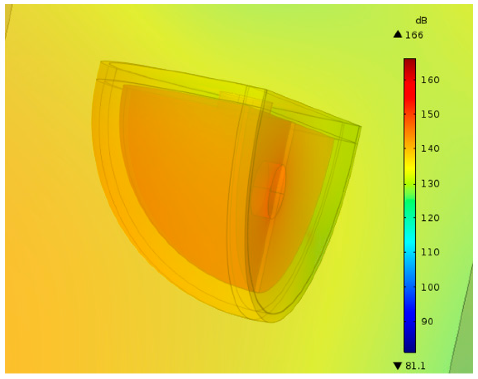
3.1. Input Sound Pressure Level
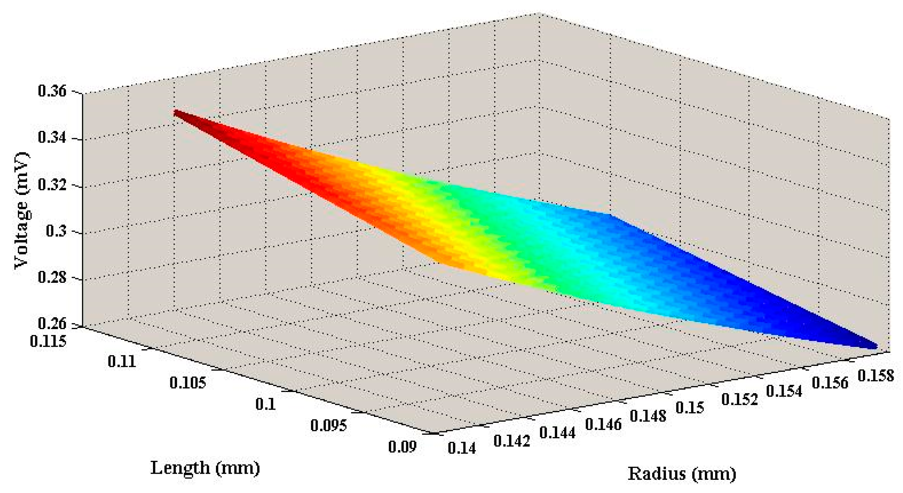
3.2. Output Voltage
3.3. Output Power
4. Conclusions
Author Contributions
Funding
Conflicts of Interest
References
- Dutoit, N.E.; Wardle, B.L.; Kim, S.-G. Design considerations for mems-scale piezoelectric mechanical vibration energy harvesters. Integr. Ferroelectr. 2005, 71, 121–160. [Google Scholar] [CrossRef]
- Zhou, S.; Wang, J. Dual serial vortex-induced energy harvesting system for enhanced energy harvesting. AIP Adv. 2018, 8, 075221. [Google Scholar] [CrossRef]
- Zhou, Y.; Zhang, S.; Ding, Y. Efficient solar energy harvesting and storage through a robust photocatalyst driving reversible redox reactions. Adv. Mater. 2018, 30, 1802294. [Google Scholar] [CrossRef] [PubMed]
- Lim, C.Y.; Jeong, Y.; Kim, K.W. A High-Efficiency Power Supply from Magnetic Energy Harvesters. In Proceedings of the International Power Electronics Conference (IPEC-Niigata 2018-ECCE Asia), Niigata, Japan, 20–24 May 2018; pp. 2376–2379. [Google Scholar]
- Pillai, M.A.; Deenadayalan, E. A review of acoustic energy harvesting. Int. J. Precis. Eng. Manuf. 2014, 15, 949–965. [Google Scholar] [CrossRef]
- Khan, F.U. Izhar State of the art in acoustic energy harvesting. J. Micromech. Microeng. 2015, 25, 023001. [Google Scholar] [CrossRef]
- Hajati, A.; Kim, S.-G. Ultra-wide bandwidth piezoelectric energy harvesting. Appl. Phys. Lett. 2011, 99, 083105. [Google Scholar] [CrossRef] [Green Version]
- Toyama, M.; Kubo, R.; Takata, E.; Tanaka, K.; Ohwada, K. Characterization of piezoelectric properties of PZT thin films deposited on Si by ECR sputtering. Sens. Actuators A Phys. 1994, 45, 125–129. [Google Scholar] [CrossRef]
- Liu, F.; Phipps, A.; Horowitz, S.; Ngo, K.; Cattafesta, L.N.; Nishida, T.; Sheplak, M. Acoustic energy harvesting using an electromechanical Helmholtz resonator. J. Acoust. Soc. Am. 2008, 123, 1983–1990. [Google Scholar] [CrossRef]
- Cai, C.; Mak, C.M. Acoustic performance of different Helmholtz resonator array configurations. Appl. Acoust. 2018, 130, 204–209. [Google Scholar] [CrossRef]
- Yuan, M.; Cao, Z.; Luo, J.; Pang, Z. Low frequency acoustic energy harvester based on a planar Helmholtz resonator. AIP Adv. 2018, 8, 085012. [Google Scholar] [CrossRef] [Green Version]
- Khan, F. Izhar: Piezoelectric type acoustic energy harvester with a tapered Helmholtz cavity for improved performance. J. Renew. Sustain. Energy 2016, 8, 705–709. [Google Scholar] [CrossRef]
- Peng, X.; Wen, Y.; Li, P.; Yang, A.; Bai, X. Enhanced acoustoelectric coupling in acoustic energy harvester using dual helmholtz resonators. IEEE Trans. Ultrason. Ferroelectr. Freq. Control 2013, 60, 2121–2128. [Google Scholar] [CrossRef] [PubMed]
- Bourquard, C.; Noiray, N. Stabilization of acoustic modes using Helmholtz and Quarter-Wave resonators tuned at exceptional points. J. Sound Vib. 2019, 445, 288–307. [Google Scholar] [CrossRef] [Green Version]
- Li, B.; Laviage, A.J.; You, J.H.; Kim, Y.-J. Harvesting low-frequency acoustic energy using quarter-wavelength straight-tube acoustic resonator. Appl. Acoust. 2013, 74, 1271–1278. [Google Scholar] [CrossRef]
- Hussain, M.; Rupp, F.; Wendel, H.P.; Gehring, F.K. Bioapplications of acoustic crystals: A review. TrAC Trends Anal. Chem. 2018, 102, 194–209. [Google Scholar] [CrossRef]
- Wu, L.-Y.; Chen, L.-W.; Liu, C.-M. Acoustic energy harvesting using resonant cavity of a sonic crystal. Appl. Phys. Lett. 2009, 95, 013506. [Google Scholar] [CrossRef]
- Zhao, H.; Xiao, X.; Xu, P.; Zhao, T.; Song, L.; Pan, X.; Mi, J.; Xu, M.; Wang, Z.L. Dual-Tube Helmholtz Resonator-Based Triboelectric Nanogenerator for Highly Efficient Harvesting of Acoustic Energy. Adv. Energy Mater. 2019, 9, 1902824. [Google Scholar] [CrossRef]
- Eghbali, P.; Younesian, D.; Farhangdoust, S. Enhancement of the low-frequency acoustic energy harvesting with auxetic resonators. Appl. Energy 2020, 270, 115217. [Google Scholar] [CrossRef]
- Ahmad, I.; Hassan, A.; Anjum, M.U.; Malik, S.; Ali, T. Ambient Acoustic Energy Harvesting using Two Connected Resonators with Piezoelement for Wireless Distributed Sensor Network. Acoust. Phys. 2019, 65, 471–477. [Google Scholar] [CrossRef]
- Horowitz, S.B.; Sheplak, M.; Cattafesta, L.N.; Nishida, T. A MEMS acoustic energy harvester. J. Micromech. Microeng. 2006, 16, S174–S181. [Google Scholar] [CrossRef]
- Yuan, M.; Cao, Z.; Luo, J.; Zhang, J.; Chang, C. An efficient low-frequency acoustic energy harvester. Sens. Actuators A Phys. 2017, 264, 84–89. [Google Scholar] [CrossRef]
- Priya, S.; Daniel, J.I. Energy Harvesting Technologies; Springer: New York, NY, USA, 2008. [Google Scholar]
- Sabine, H. Room acoustics. Trans. IRE Prof. Group Audio 1953, 42, 4–12. [Google Scholar] [CrossRef]
- Zhou, C.; Liu, B.; Li, X.; Tian, J. Effect of cavity wall elasticity on acoustic characteristics of a water-filled Helmholtz resonator: Equivalent concentrated parameter model of a cylindrical cavity. Chin. J. Acoust. 2007, 32, 426–434. [Google Scholar]
- Chanaud, R. Effects Of Geometry On The Resonance Frequency Of Helmholtz Resonators. J. Sound Vib. 1994, 178, 337–348. [Google Scholar] [CrossRef]
- Kinsler, L.E.; Frey, A.R.; Bennett, G.S. Fundamentals of Acoustics. Am. J. Phys. 1951, 19, 254–255. [Google Scholar] [CrossRef]
- Roundy, S. On the effectiveness of vibration-based energy harvesting. J. Intell. Mater. Syst. Struct. 2005, 16, 809–823. [Google Scholar] [CrossRef]
- DuToit, N.E.; Wardle, B.L. Experimental verification of models for microfabricated piezoelectric vibration energy harvesters. AIAA J. 2007, 45, 1126–1137. [Google Scholar] [CrossRef]
- Anton, S.R.; Sodano, H.A. A review of power harvesting using piezoelectric materials (2003–2006). Smart Mater. Struct. 2007, 16, R1–R21. [Google Scholar] [CrossRef]
- Cheng, H.-H.; Huang, Z.-R.; Wu, M.; Fang, W. Low Frequency Sound Pressure Level Improvement of Piezoelectric Mems Microspeaker Using Novel Spiral Spring with Dual Electrode. In Proceedings of the 20th International Conference on Solid-State Sensors, Actuators and Microsystems & Eurosensors XXXIII (Transducers & Eurosensors XXXIII), Berlin, Germany, 23–27 June 2019; pp. 2013–2016. [Google Scholar]
- Qi, S.; Oudich, M.; Li, Y.; Assouar, B. Acoustic energy harvesting based on a planar acoustic metamaterial. Appl. Phys. Lett. 2016, 108, 263501. [Google Scholar] [CrossRef]
- Peng, X.; Wen, Y.; Li, P.; Yang, A.; Bai, X. A wideband acoustic energy harvester using a three degree-of-freedom architecture. Appl. Phys. Lett. 2013, 103, 164106. [Google Scholar] [CrossRef]
- Yang, A.; Li, P.; Wen, Y.; Lu, C.; Peng, X.; Zhang, J.; He, W. Enhanced Acoustic Energy Harvesting Using Coupled Resonance Structure of Sonic Crystal and Helmholtz Resonator. Appl. Phys. Express 2013, 6, 127101. [Google Scholar] [CrossRef]
- Yuan, M.; Wang, X.; Ding, Z. Low frequency acoustic energy harvesting adopting slit Helmholtz resonator. Vibroeng. Procedia 2018, 20, 151–155. [Google Scholar] [CrossRef]
- Kimura, S.; Tomioka, S.; Iizumi, S.; Tsujimoto, K.; Sugou, T.; Nishioka, Y. Improved performances of acoustic energy harvester fabricated using sol/gel lead zirconate titanate thin film. Jpn. J. Appl. Phys. 2011, 50, 1271–1295. [Google Scholar] [CrossRef] [Green Version]
- Li, B.; You, J.H.; Kim, Y.-J. Low frequency acoustic energy harvesting using PZT piezoelectric plates in a straight tube resonator. Smart Mater. Struct. 2013, 22, 55013. [Google Scholar] [CrossRef]


| Young’s Modulus (GPa) | Relative Dielectric Constant | Piezoelectric Constant (C/m2) | Mass Density (Kg/m3) | |
|---|---|---|---|---|
| Cu | 110 | 8960 | ||
| PZT-5H | 56 | 1433.6 | −6.62 | 7500 |
| Radius of Cavity (Mm) | Length of Neck (Mm) | Radius of Neck (Mm) | Thickness of Bottom (Mm) | Thickness of PZT (Mm) | Thickness of Baffle (Mm) |
|---|---|---|---|---|---|
| Rc | ln | rn | t1 | t2 | t3 |
| 1 | 0.1 | 0.15 | 0.1 | 0.05 | 0.1 |
| Reference | Material | Frequency Band |
|---|---|---|
| [32] | PZT-5H | Less than 10 Hz |
| [33] | PZT Pb(Zr1−xTix)O3 | Less than 50 Hz |
| [12] | PZT | Less than 60 Hz |
| [34] | PZT-5H | 300 Hz |
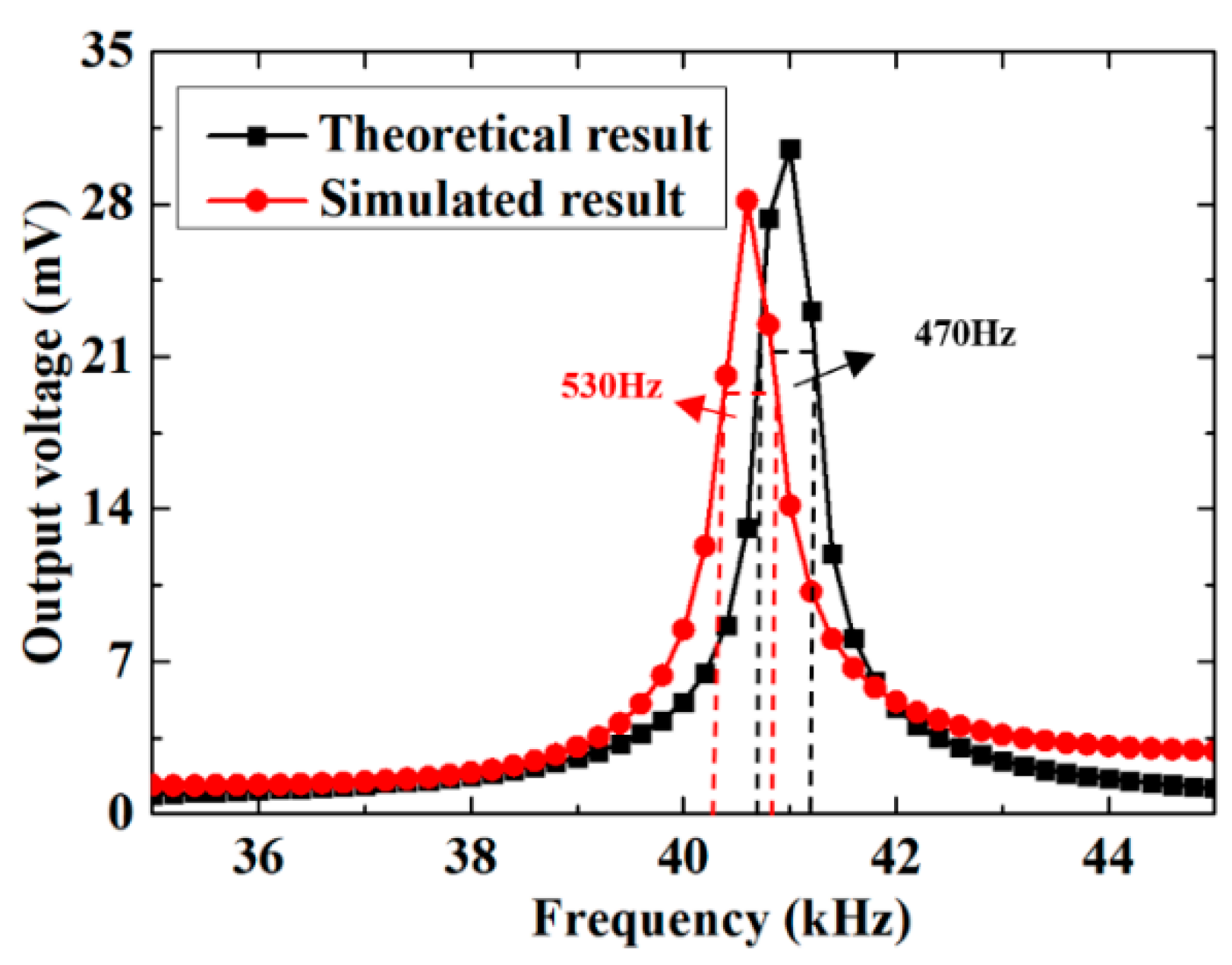
| This work | PZT-5H | 470 Hz |
| Author (Reference Number) | Energy Source | Type | Material | Dimensions | Resonant Frequency (kHz) | Power Density (µW cm−2) |
|---|---|---|---|---|---|---|
| Horowitz et al. [21] | Acoustic pressure (149 dB) | Diaphragm (ring) | PZT | d1 = 2.4 mm d2 = 2.23 mm hp = 0.267 µm | 13.6 | 0.34 |
| Kimura et al. [36] | Acoustic pressure (100 dB) | Diaphragm | PZT | d = 1.2 mm hp = 1.0 µm | 16.7 | 0.0098 |
| Li et al. [37] | Acoustic pressure (100 dB) | Cantilever | PZT | L = 40 mm b = 20 mm hp = 0.48 mm | 0.199 | 57.4 |
| This work | Acoustic pressure (135 dB) | Diaphragm | PZT | d = 1.1 mm hp = 0.05 mm | 40.6 | 12.7 |
Publisher’s Note: MDPI stays neutral with regard to jurisdictional claims in published maps and institutional affiliations. |
© 2020 by the authors. Licensee MDPI, Basel, Switzerland. This article is an open access article distributed under the terms and conditions of the Creative Commons Attribution (CC BY) license (http://creativecommons.org/licenses/by/4.0/).
Share and Cite
Ji, X.; Yang, L.; Xue, Z.; Deng, L.; Wang, D. Enhanced Quarter Spherical Acoustic Energy Harvester Based on Dual Helmholtz Resonators. Sensors 2020, 20, 7275. https://doi.org/10.3390/s20247275
Ji X, Yang L, Xue Z, Deng L, Wang D. Enhanced Quarter Spherical Acoustic Energy Harvester Based on Dual Helmholtz Resonators. Sensors. 2020; 20(24):7275. https://doi.org/10.3390/s20247275
Chicago/Turabian StyleJi, Xincun, Lei Yang, Zhicheng Xue, Licheng Deng, and Debo Wang. 2020. "Enhanced Quarter Spherical Acoustic Energy Harvester Based on Dual Helmholtz Resonators" Sensors 20, no. 24: 7275. https://doi.org/10.3390/s20247275