1. Introduction
The consumer-grade RGBD sensor has the potential to be used in many fields, such as 3D reconstruction [
1,
2], camera simultaneous localization and mapping (SLAM) [
3], robotics exploration [
4], and obstacle avoidance [
5], due to its low cost and ability to provide depth with pixel-corresponded RGB information. Based on the ranging principle, consumer-grade RGBD sensors can be categorized into three groups: time-of-flight (ToF)-based RGBD sensors (i.e., Kinect V2 [
6]), structured light pattern (SLP)-based RGBD sensors (i.e., Kinect V1 [
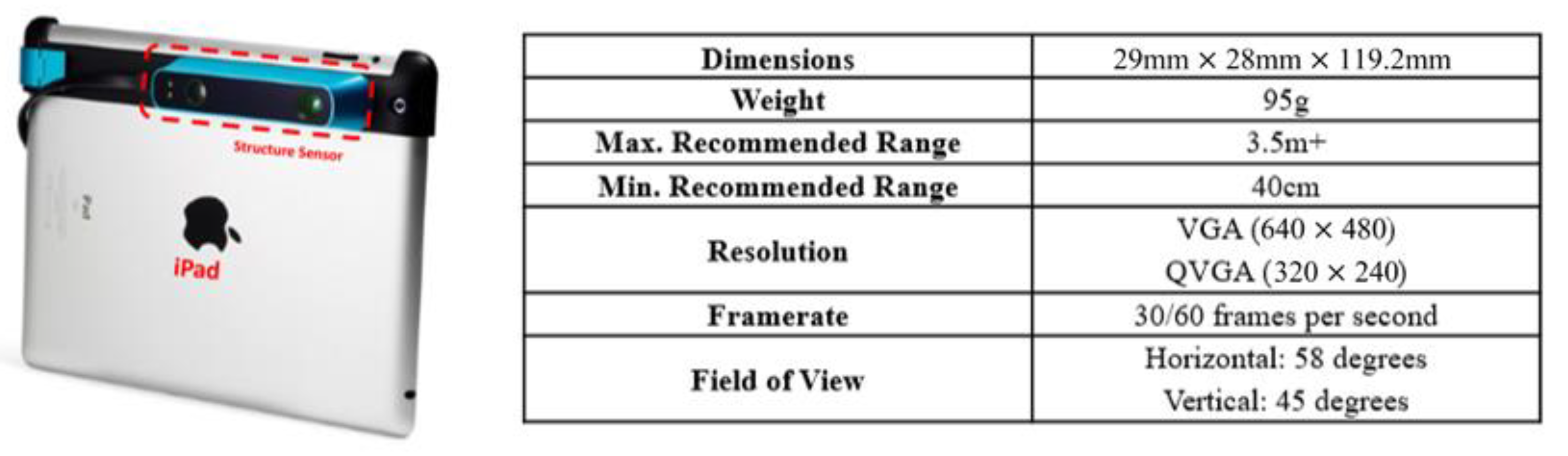
6], Structure Sensor [
7], Asus Xtion [
8], Intel RealSense [
9]), and stereo vision-based RGBD sensors (i.e., ZED camera [
10]). Although all RGBD sensors provide the same data format, SLP RGBD has become one of the most popular RGBD solutions due to its low requirement for computational power [
11]. Despite the wide use and popularity, the SLP-based RGBD sensor has one significant drawback: the errors in depth frame exponentially increase with ranging distance [
6]. Existing applications of consumer-grade SLP RGBD sensor are mainly for gaming purposes, not for those requiring high-precision, such as SLAM and visual odometery [
12]. With high-precision applications, the accuracy of depth measurement is crucial as errors in depth will be accumulated during the frame matching process, which will significantly affect the quality of final 3D point cloud and position products and may cause a frequent loss tracking problem. Thus, proper calibration of depth measurements is required for SLP RGBD sensors [
13].
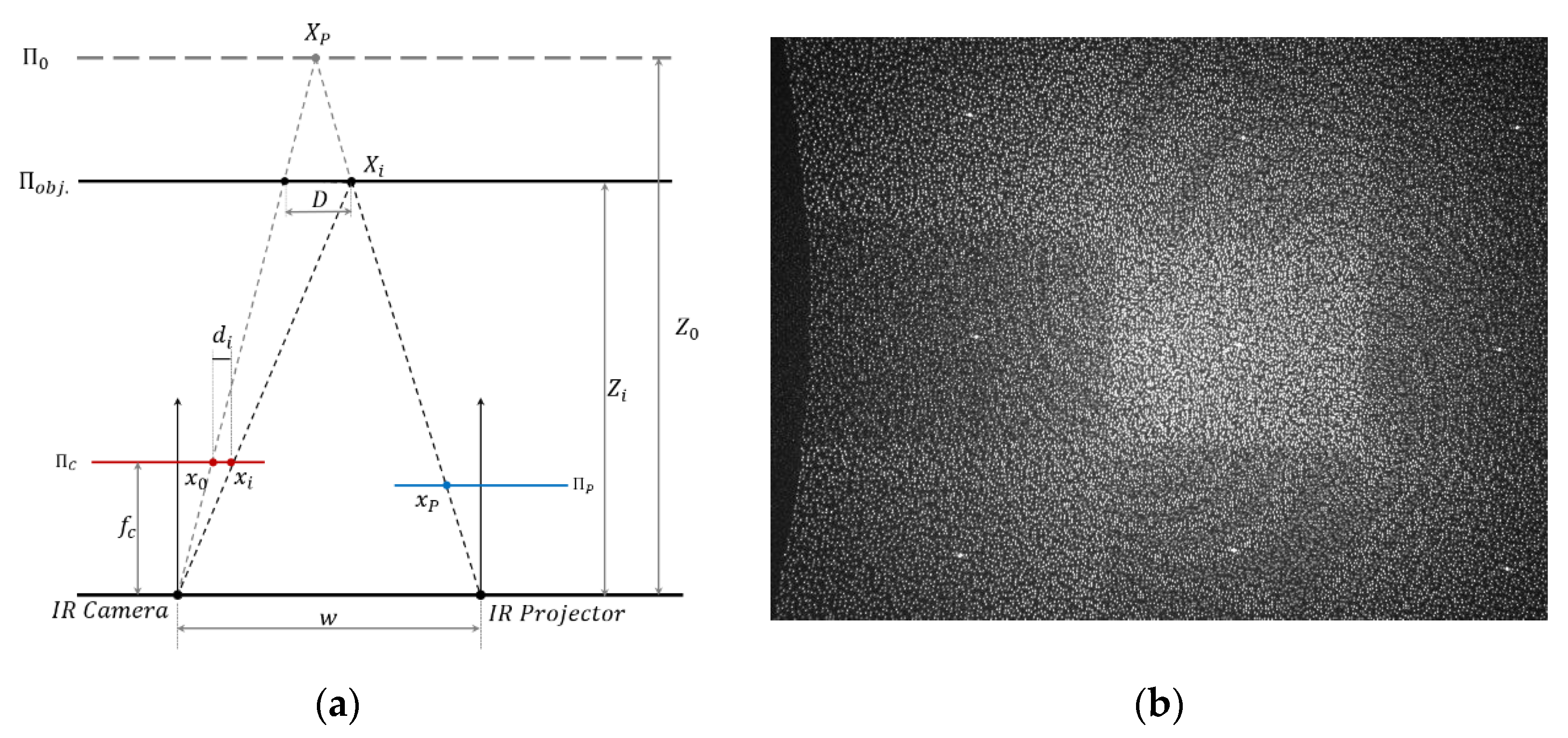
The SLP RGBD sensor calculates ranging information based on the disparity
(pixel difference,
) between the reference pixel
location of the pre-structured pattern
in the reference plane
and the measure pixel location
of captured pattern
on the object plane
in the received image frame, as shown in
Figure 1a. The reference pixel
of the pre-structured pattern is fixed in the image plane
. The pre-structured pattern as shown in
Figure 1b, is a fixed pattern of light and dark speckles. The depth is calculated by triangulation against the pre-structured pattern. If the captured feature
can be matched to the reference pixel
, the disparity
can be obtained. For a commercial SLP RGBD sensor, information including the actual pattern
in the projector plane
and the distance
from the IR projector to the reference plane
remains undisclosed.
For the object
, the depth
can be expressed as:
where,
is the reference distance from the sensor to the reference plane ;
is the focal length of IR camera;
is the baseline between the IR camera and IR projector;
is the disparity for .
For commercial RGBD sensors, such as Structure Sensor and Kinect V1, the actual disparity
in pixel unit is not available to the users. Instead, a normalized disparity
value from 0 to 2047 is outputted. Normalized disparity is expressed as Equation (2),
m, n are the normalized parameters that remain unknown:
Combine (1) and (2):
where:
,
&
are fixed parameters of a RGBD sensor, and are provided by the manufacturer to calculate the depth
from the normalized disparity
.
Early works on SLP RGBD calibration [
6,
15] described the systematic error in the depth frame as a function of radial distortion parameters and adopted the classic RGB camera distortion model [
16] to correct the radially symmetric error on the SLP-based RGBD sensor. However, they failed to address the fact that the distortion increases with distance. Zhang and Zhang [
17] proposed a depth dependent calibration model that separately fits a linear equation of the actual depth and the rotation angle for each pixel. The limitations for this method are the instability of the algorithm, the requirement of accurate initial parameters to avoid divergence, and the high computational cost. Similarly, Canessa et al. [
18] proposed a labour intense empirical calibration model by using the sample images captured from 0.6 to 2 m to fit a second degree polynomial model for each pixel. Recently, Darwish et al. [
19] proposed a calibration model, treating the depth distortion of a RGBD sensor as a combined centrosymmetric error of the IR camera distortion and IR projector distortion with same optical centre. A look up table of calibration parameters was calculated at different distance, i.e., from 0.5 to 3 m with 0.5 m interval. With insufficient investigation of the mechanism of how the IR camera and IR projector contribute to the overall non-centrosymmetric distortion of the RGBD sensor, and also being a distance-based calibration model, this method suffers large offsets in the edge area of depth frame and requires a look up table for parameters in different distance. Similar problems can be found in [
20].
A visual camera or a RGB camera often have a centrosymmetric or near centrosymmetric distortion pattern. When the distortion model is adopted in RGBD sensor calibration, the assumption that the distortion of SLP RGBD is also centrosymmetric and can be modeled by a classic distortion model is accepted by many researchers [
15,
20,
21,
22]. However, compared to visual distortion that can use one model to represent the distortion, current calibration models for SLP RGBD sensors are much more complex due to the additional work such as fitting the model separately based on distance, the requirement of good initial parameters, and the larger number of parameters to provide full range coverage. The complexity of current calibration models as discussed later in this paper is mainly due to the negligence of the fundamental difference between the visual camera and the SLP RGBD sensor. One significant difference between visual camera and SLP RGBD sensor is that the distortion in the depth frame of the RGBD sensor is caused by both camera lens and projector lens while image distortion is only caused by the camera lens. In fact, due to the combined effects of camera and projector, the depth distortion is non-centrosymmetric rather than the centrosymmetric distortion in the visual camera. Therefore, the existing methods that only use a centrosymmetric distortion model to calibrate the depth distortion, for example the method of Darwish et al. [
19], will inevitably suffer large offset in the frame edge area. The edge area is extremely sensitive to the high order part in the visual camera distortion model [
16]. Furthermore, the target measurement of SLP RGBD sensors to apply the distortion model should be disparity rather than depth, as disparity is the raw measurements of distance measurement. A camera distortion model was originally designed for calibrating the distorted pixel caused by camera lens. Although a similar distortion pattern can be discovered in depth frames, it is actually a reciprocal product of the pixel difference (disparity) between the captured pattern and reference pattern. By analyzing the distortions of the camera and the projector separately, this paper proposes a new distortion model to calibrate disparity which can be applied to full range depth frames of SLP-based RGBD sensors. Compared to the current methods, the proposed method is distance independent.
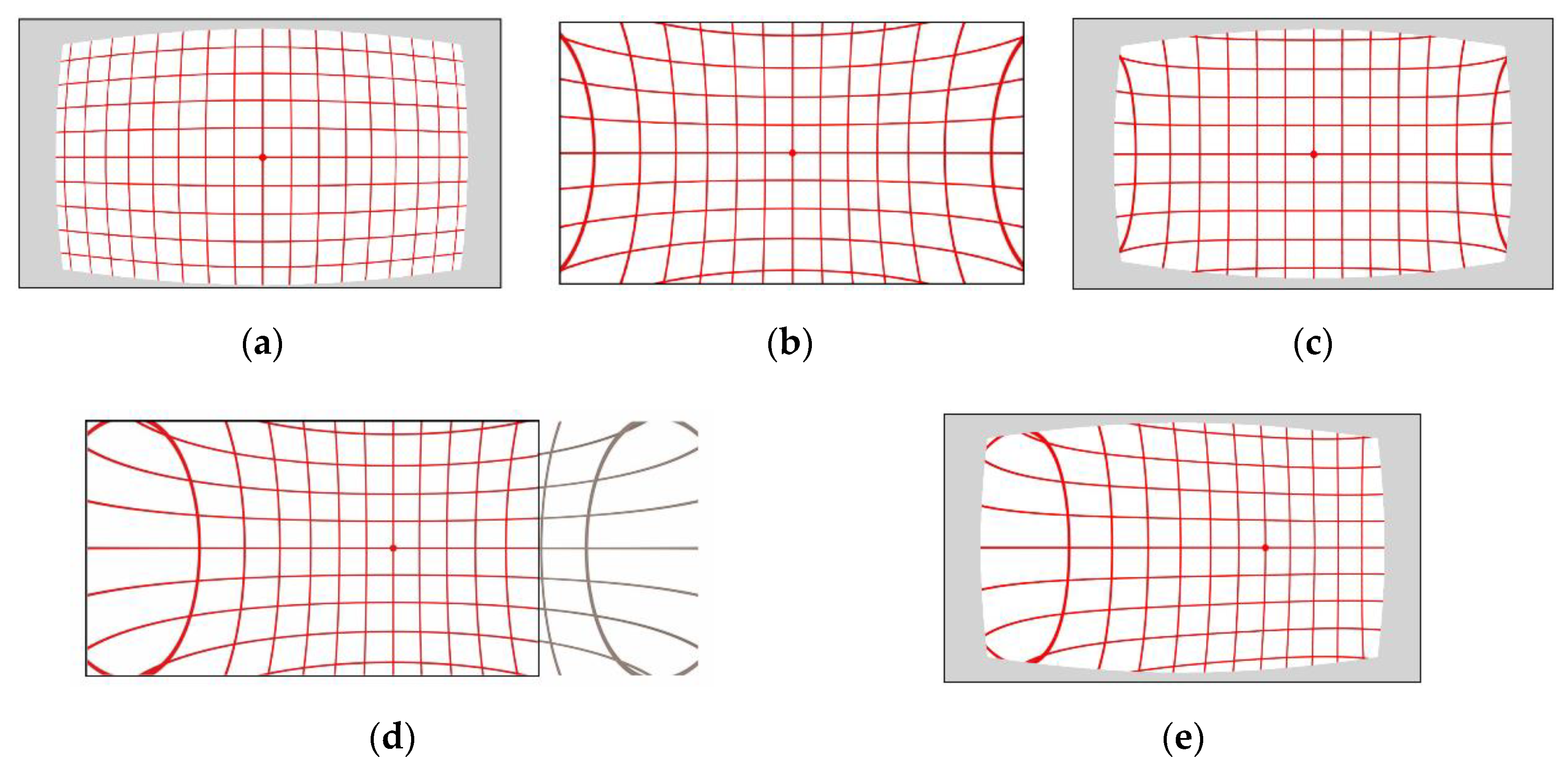
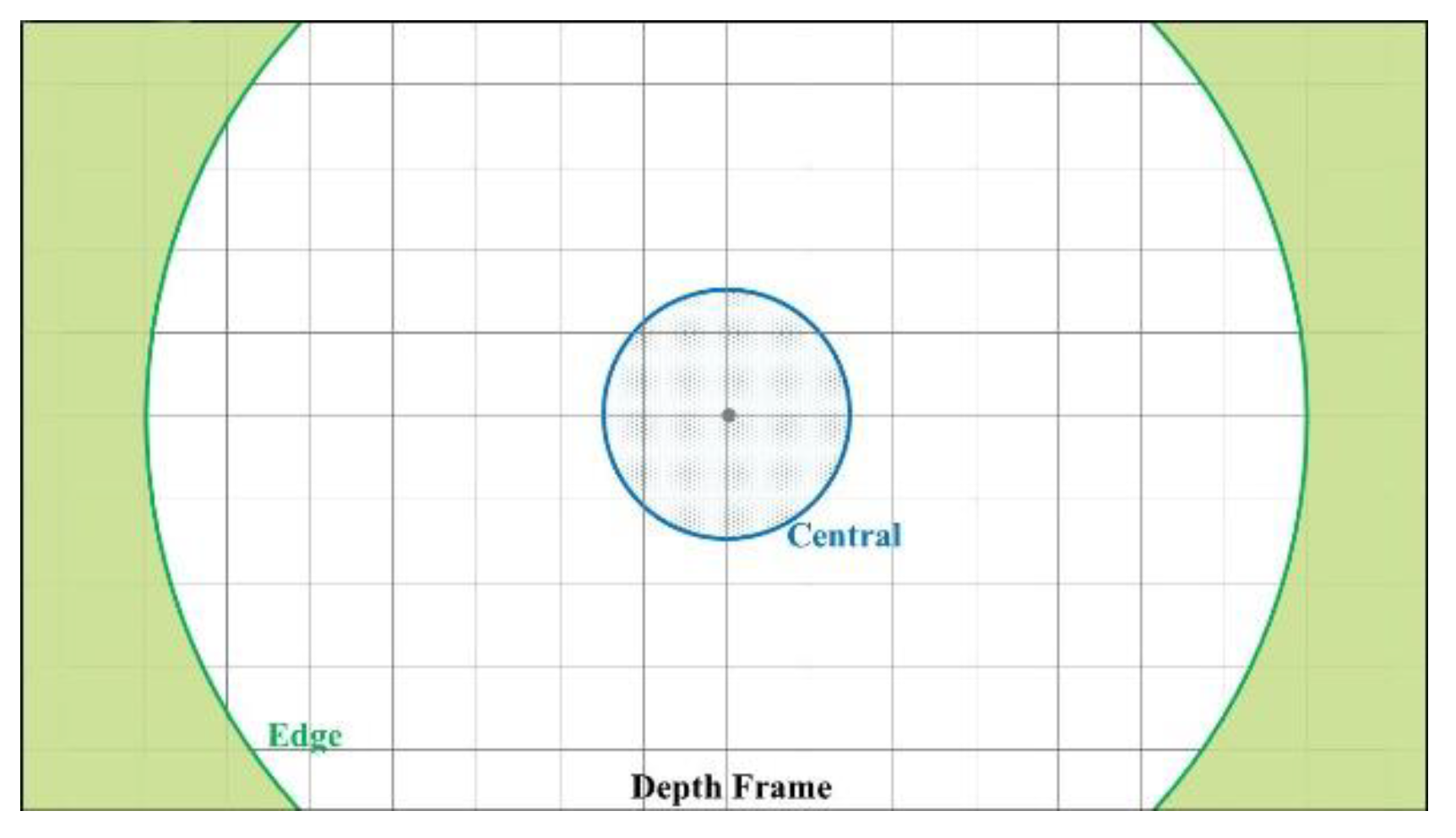
This paper firstly makes a comprehensive discussion of the sources and forms a mechanism of depth distortion of the SLP RGBD sensors. By compositing the calibration model that is strictly based on actual physical model of camera distortion and projector distortion, we propose a new method which can effectively and accurately calibrate the full range depth data. The proposed method calibrates the whole range depth with just one model and one set of parameters. Compared to the existing model that requires to separately fit calibration parameters for different distance range or a look up table of parameters, the proposed method largely improved the efficiency of the calibration procedure. By applying the proposed calibration model, we can accurately improve the ranging accuracy by 70% in the central area and 65% in the edge area of the depth frame. Two distortions and one infrared cone related bias will be used to model the overall systematic error of SLP sensors. The two distortions are a pincushion distortion caused by the projector lens and a barrel distortion caused by infrared camera lens, shown in
Figure 2. A bias caused by the infrared cone that cannot illuminate the homogeneously for a unified pattern recognition performance [
6,
23] is also modeled in the proposed calibration method. As the systematic error is extremely sensitive to how these two distortions and the bias overlapped, accurately determining the forming mechanism of the overall distortion is crucial for calibration.
Then a two-step calibration procedure is proposed to overcome the problem that the commuter-grade RGBD sensor often remains a black box to the users. SLP RGBD sensors such as Kinect V1 [
24] and Structure Sensor [
7] only provide a normalized disparity unit, but the raw disparity measurement and the normalization parameters for disparity remain unknown. Other information, such as original reference pattern and the actual measurement of the captured pattern, is also unavailable to users. Such black box environment is extremely problematic for the sensor calibration. Although the camera distortion and camera internal parameters can be calibrated by traditional checkboard method [
25], the projector distortion cannot be easily calibrated with existing methods [
26,
27,
28] which all require knowing the original reference pattern and take measurement of the casted pattern in real world. The two-step calibration procedure is proposed to achieve a precise calibration procedure in such black box environment for RGBD sensor. The two-step calibration procedure includes: (1) the IR camera related distortion is calibrated with classic checkboard method; (2) the projector distortion in normalized disparity is modeled by a new combined objective function.
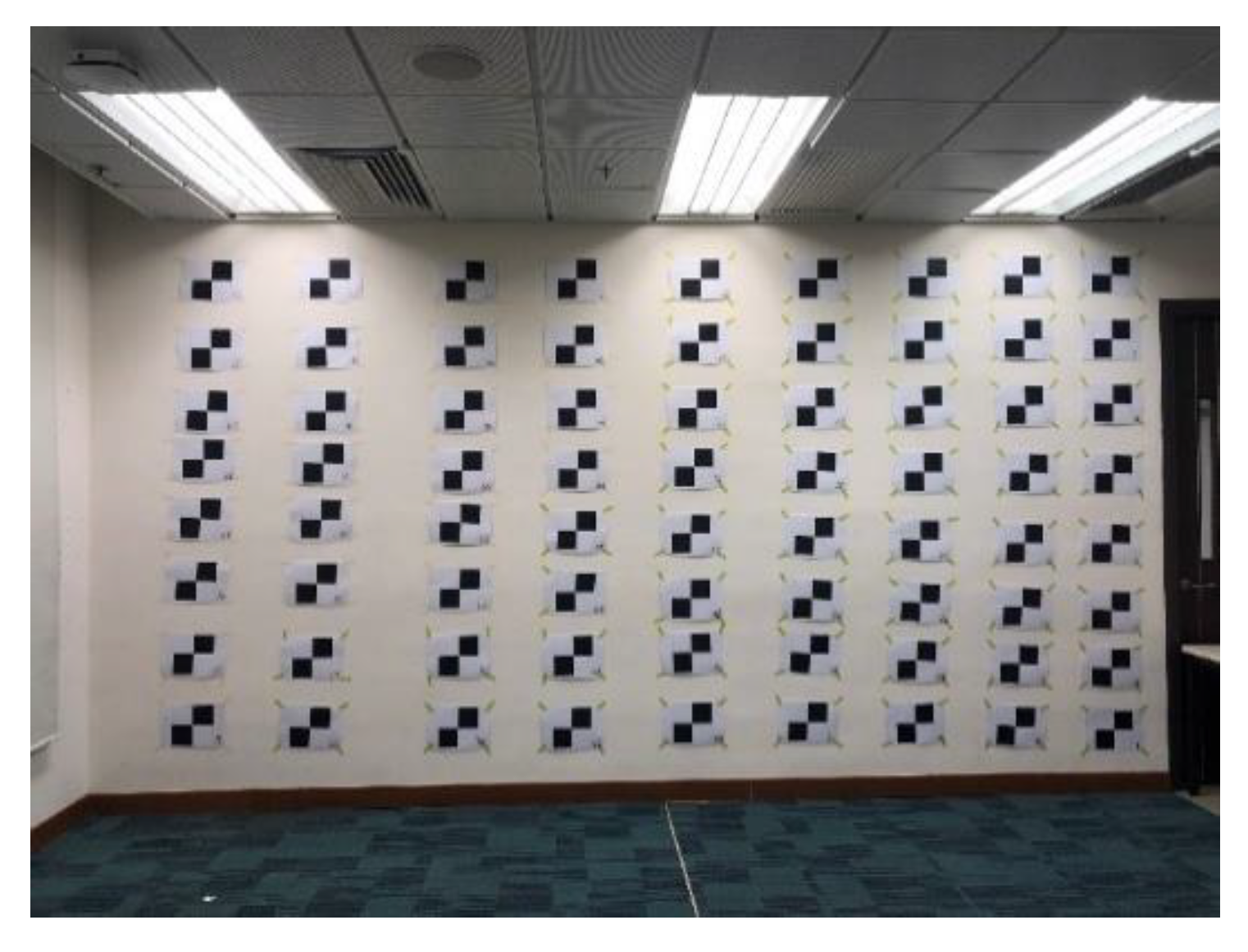
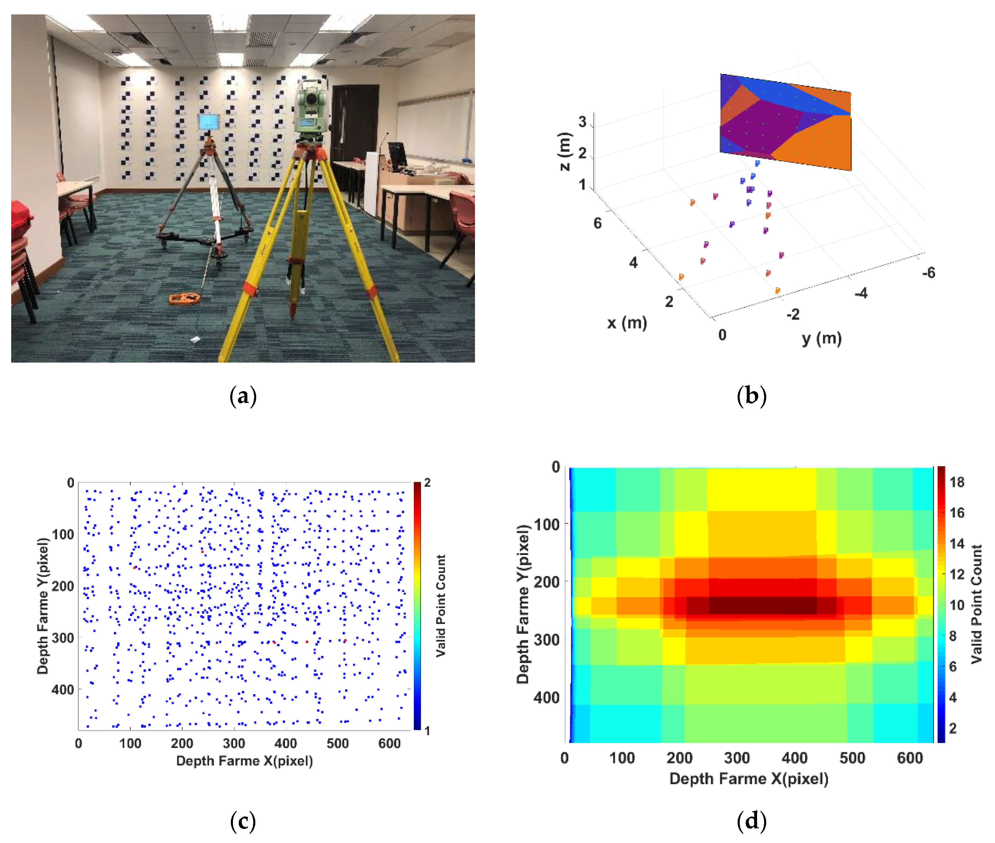
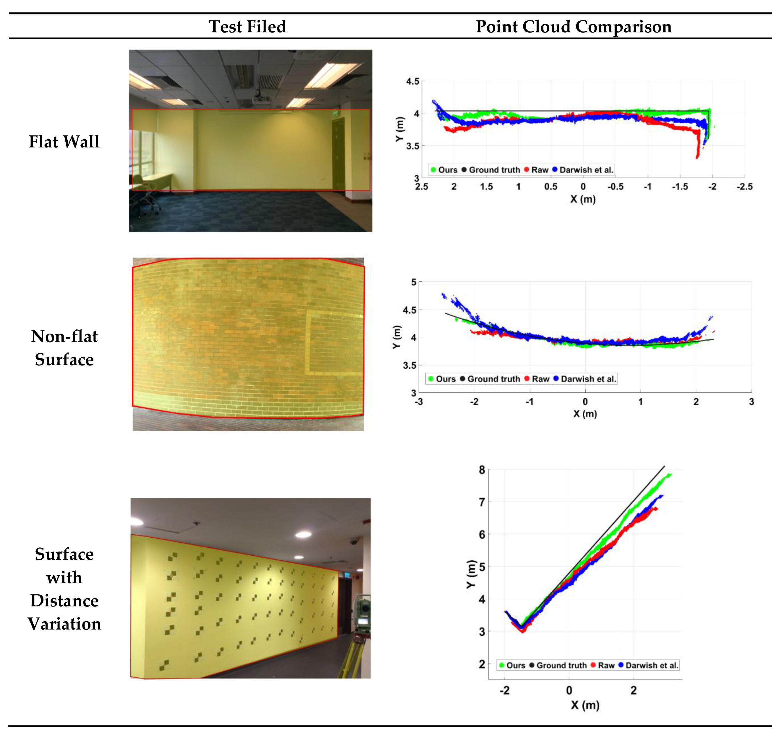
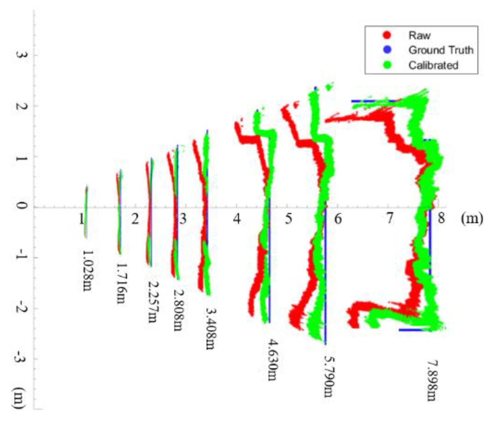
The calibration method is evaluated by two experiments in an indoor environment. One is an experiment designed to test the performance of the calibration model. A set of test data with ground truth error is acquired in three different scenes: (1) flat surface, (2) non-flat surface, and (3) flat surface with distance variation. The ground truth error is obtained by plane fitting and compared with the modeled error generated from the proposed method. Comparison results demonstrate that the proposed method can precisely model the systematic error caused by non-centrosymmetric distortion of the RGBD sensor. The other one is an evaluation of proposed method in actual point cloud collected in the indoor environment. By comparing the calibrated and uncalibrated point cloud in the whole working range of the tested SLP sensor, the improvement of the calibration model can be demonstrated clearly.
2. RGBD Distortion Model
To calibrate the SLP based RGBD sensor, it is important to understand how the error is introduced in the RGBD sensor and how that error affects the depth measurements. The radical systematic error appeared in the depth frame is mainly a combined result of the distortions caused by camera lens and projector lens. The infrared cone also causes a certain radical error to the depth frame. In this section, the mechanism of the non-centrosymmetric distortion of RGBD sensor will be revealed.
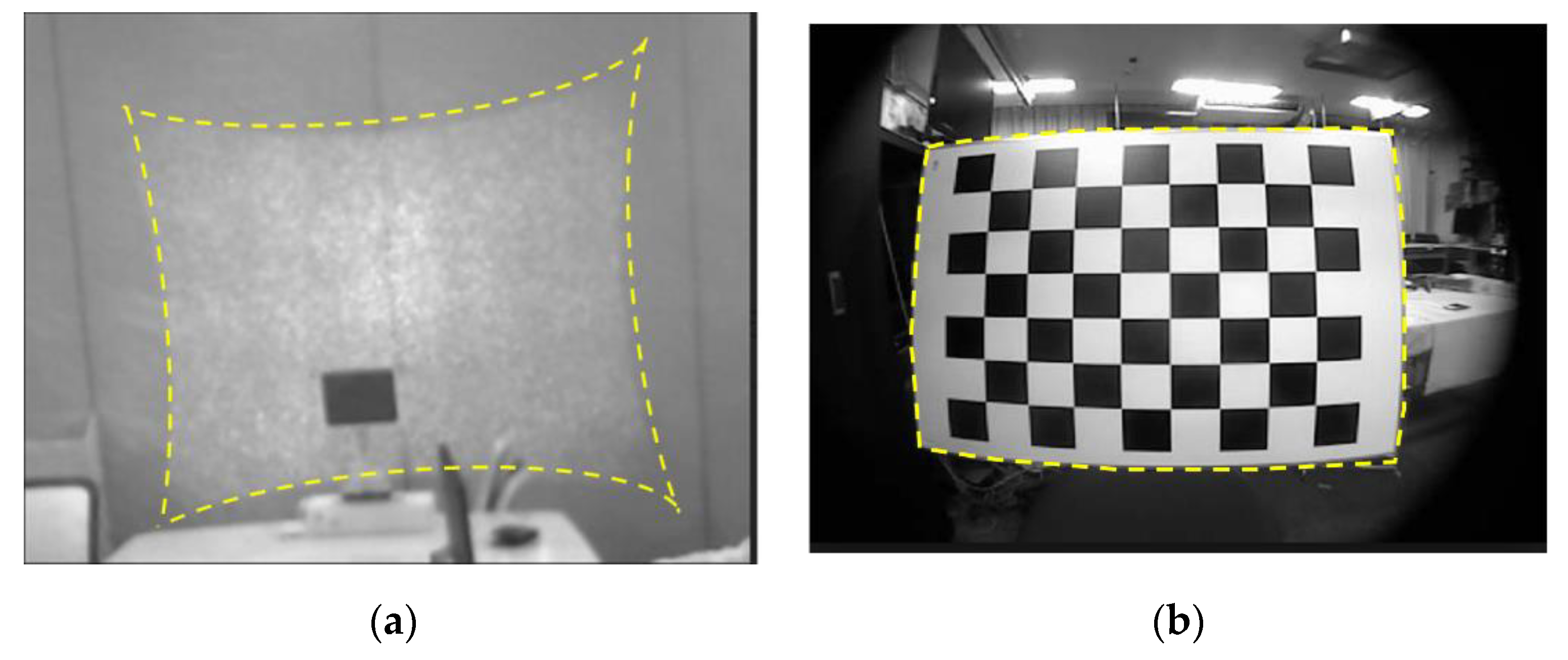
The distortion appearing in the disparity measurement of SLP RGBD sensor can be traced back to the two optical lenses in its hardware, the projector lens and camera lens. The projector lens causes a pincushion distortion as shown in
Figure 2a; and the camera lens causes a barrel distortion as shown in
Figure 2b. As the pattern is casted in IR and can’t be captured by normal digital camera,
Figure 2a is captured by a calibrated IR camera called MIQUS M3 [
29].
Figure 2b is captured by the IR camera. Both pincushion and barrel distortion are optical distortions, therefore, they occur as a result of optical design and lens error. They both appear and overlap in the disparity measurement of a SLP RGBD sensor.
The data accessed by users are the normalized disparity unit, which is a normalized pixel difference between the pre-stored reference pattern and the captured pattern. The most basic observation of SLP RGBD sensor is the disparity between the pre-stored distortion-free reference pixel and the captured distortion affected measure pixel . The distortion first appeared in the measured pixel and then passed down to the disparity and normalized disparity.
The pincushion distortion occurred when the pre-stored pattern was casting through the projector lens into the object scene. As shown in
Figure 2a, the reference pattern (rectangle shape) would be distorted into a pincushion shape (marked as yellow in
Figure 2a). When the pincushion distortion pattern in the object space was then captured by the IR camera’s complementary metal–oxide–semiconductor (CMOS) sensor [
30], the camera lens would cause additional barrel distortion (
Figure 2b) to the already distorted casted pattern. As a result, the captured patterns, which is used to calculate disparity, contains the distortion caused by both IR projector lens and IR camera lens and two types of distortion overlapped in the image plane. Since the disparity, or normalized disparity, are the linear products of the captured pattern, the distortion model that is applicable to capture pattern in pixel unit can also be applied in the disparity or normalized disparity.
Considering both camera and projector distortions, the measured disparity in pixel can be described as:
where,
is the measurement value of disparity in pixel;
is the true value of disparity in pixel with no error;
is the distortion error caused by camera lens in pixel;
is the distortion error caused by projector lens in pixel.
According to Zhang [
17], the optical distortion of the optical lens can be modeled as:
where,
= distorted image point as projected on image plane;
= undistorted image point as projected by an ideal pinhole camera;
= distortion centre;
radial distortion coefficient;
tangential distortion coefficient; and
.
Camera distortion is normally barrel distortion with a negative term for , and projector distortion is often pincushion distortion with a positive .
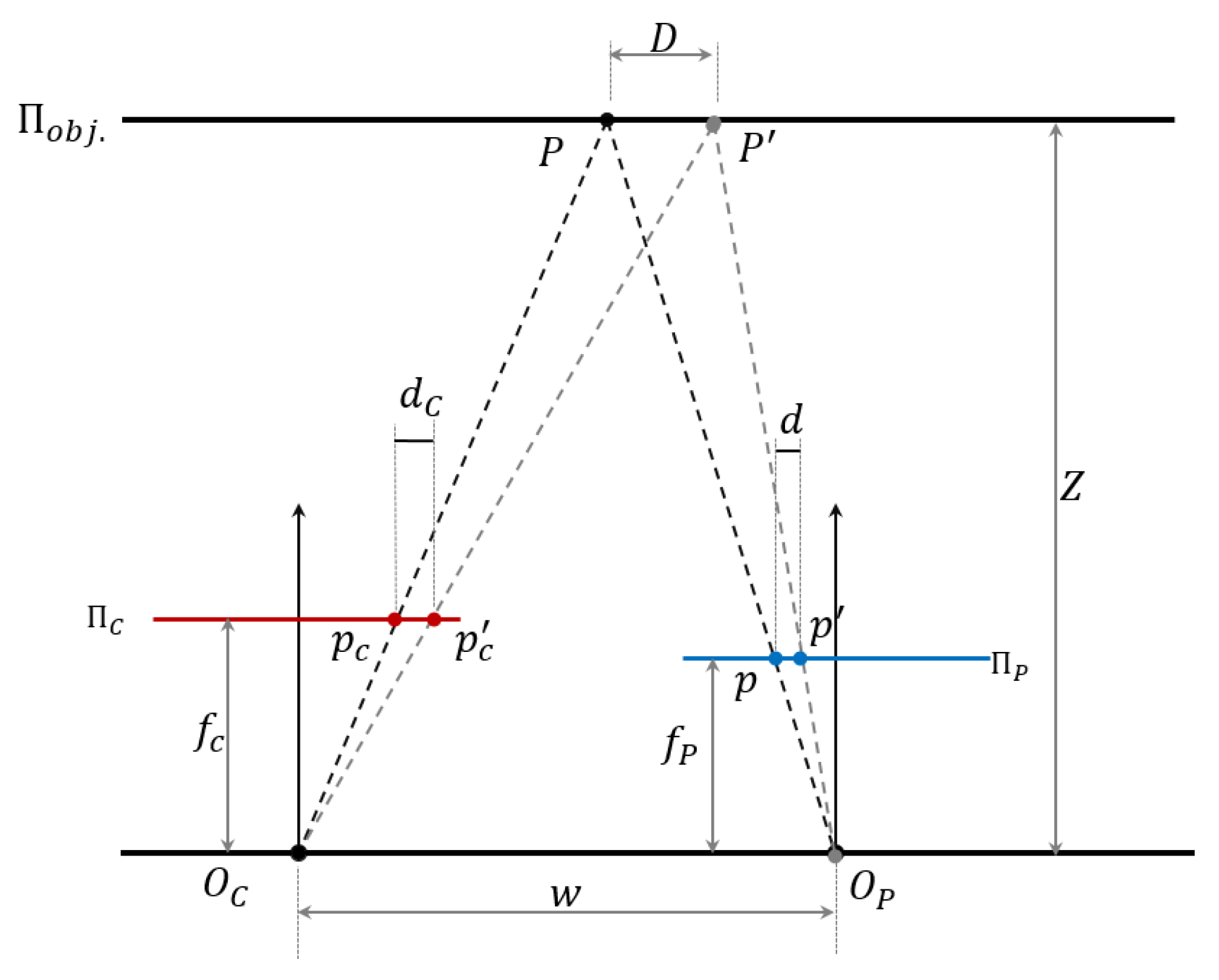
Both the camera-caused barrel distortion and projector-caused pincushion distortion are uncorrelated to the distance. The camera-caused barrel distortion in the disparity is a fixed centrosymmetric distortion with a centre at the optical centre of the IR image plane for the whole distance. For the pincushion distortion of the projector lens, it can be proved that the casted projector distortion’s effect in the image plane is uncorrelated with distance, and same as the barrel distortion caused by the camera lens, the pincushion distortion on the image plane should be a fixed distortion for all distances. It is because the ratio between the original pincushion distortion in projector plane and the captured pincushion distortion in image plane is a constant value for all the distances.
Figure 3 illustrates that the pixel distortion
in projector plane
caused by the projector lens in the object scene has a fixed relationship with the pincushion distortion
that appeared in the image plane
.
Where,
is the focal length of projector lens and camera lens;
is the optical centre of the projector lens and camera lens;
is the object plane;
is the projector pattern plane;
is the camera image plane;
is the undistorted and distorted pattern location in projector pattern plane ;
is the undistorted and distorted pattern location casted into the object plane ;
is the undistorted and distorted pixel captured by camera in image plane ;
is the pixel difference in projector plane ;
is the pixel difference in image plane ;
is the location difference in object plane ;
is the baseline between camera centre and projector centre;
is the distance from baseline to object plane.
As shown in
Figure 3, pixel difference
is the pincushion distortion in the projector plane
. When this distortion is projected into the object plane
, it is presented as the location difference
between the actual casting location
and the undistorted location
. As here we are discussing the projector distortion’s effect on the image plane, the camera distortion is not considered for better visualization. In actual sensor measurement, the projector distortion and camera distortion are overlapped in image plane and have a combined effect on the distorted pixel
. With no camera lens barrel distortion considered, the location difference
in the object plane
will be captured as the pixel difference
in image plane
. From
Figure 3, the following equation can be obtained:
Combine the two parts in Equation (6), the following relationship can be obtained:
Since is a constant value, therefore, no matter what the distance is, the pixel shift in the image plane caused by the projector lens follows the same model as the original pincushion distortion in the projector plane and just with an additional scale . The scale can be put into the parameters of Equation (5) as new parameters in the distortion model. Therefore, the distortion impact from projector in image plane follows the same pincushion model in projector plane and is not correlated to the distance from the projector to the object.
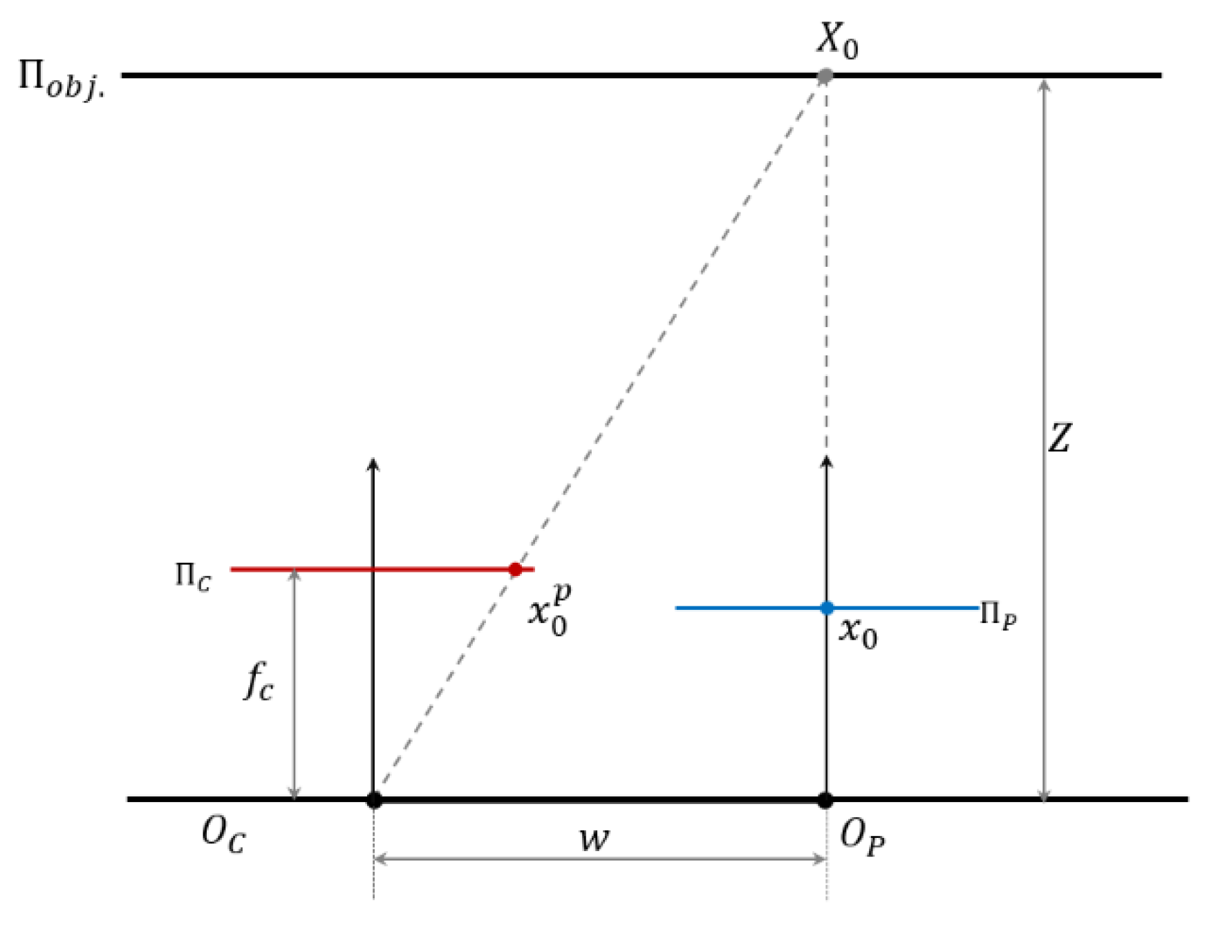
Both camera barrel distortion and projector pincushion distortion are centrosymmetric distortion in the normalized disparity unit. The camera barrel distortion is constant at the optical centre of the IR image plane for all the distance range. For the pincushion distortion appeared in the image plane, although it is still a centrosymmetric distortion, it has varying distortion centre
based on the distance
. In the SLP RGBD sensor’s chipset, the disparity is only calculated from the pixel difference in the x axis, and for this reason, the y coordinates
of the pincushion distortion centre are always equal to 0. The x coordinates of
varies based on the distance. Based on the geometry shown in
Figure 4, the image coordinates of projector centre
in image plane can be calculated as Equation (8).
Although both the barrel distortion and pincushion are centrosymmetric distortion in the disparity unit, the combined overall distortion is a non-centrosymmetric distortion due to the pincushion distortion’s varying centre. If the centrosymmetric barrel distortion and pincushion distortion have the same distortion centre in the image plane, as shown in
Figure 5a,b, then the overlapped distortion, shown in
Figure 5c, is also a centrosymmetric distortion with the distortion in the optical centre of the image frame. According to Equation (8), the pincushion distortion centre
in the image frame is always different from the barrel distortion centre. Although the pincushion distortion in a shifted centre is still a centrosymmetric pattern (
Figure 5d), its overlapping result with a barrel distortion of different distortion centre will become a non-centrosymmetric pattern, as shown in
Figure 5e. Therefore, the overall distortion in the SLP RGBD sensor has a non-centrosymmetric pattern. The typical distortion pattern is similar to that illustrated in
Figure 5e, with distortion centre (the least distorted part) shifted from the optical centre to the side of the projector module and the far side away from the projector centre suffering more severe distortion than the other side.
Normalize the disparity in Equation (4) using Equation (2):
where,
is the measurement value of normalized disparity;
are the normalize parameter of disparity;
is the true value of disparity in pixel with no error;
is the distortion error caused by camera lens in pixel;
is the distortion error caused by projector lens in pixel;
is the true value of normalized disparity.
Based on the Brown’s model [
31],
and
can be expanded to radial distortion part and tangential distortion part as:
The distortion model can be expressed as:
where,
is the radial distortion of the IR camera;
is the tangential distortion of the IR camera;
is the radial distortion of the IR projector;
is the tangential distortion of vIR projector;
, ;
is the camera or projector centre;
is measured image coordinate;
is the parameters of radial distortion model;
is the parameters of tangential distortion model.
In this way, Equation (10) can be further expanded as:
where,
are the distortion parameters of the IR camera;
; ; ;
is the centre point of camera;
is the measured image position;
are the distortion parameters of the IR projector;
; ; ;
is the centre point of projector distortion model in image coordinates;
is the measured image position without the influence of camera distortion.
Combine (9), (10) & (12), the proposed calibration model in normalized disparity can be expressed as:
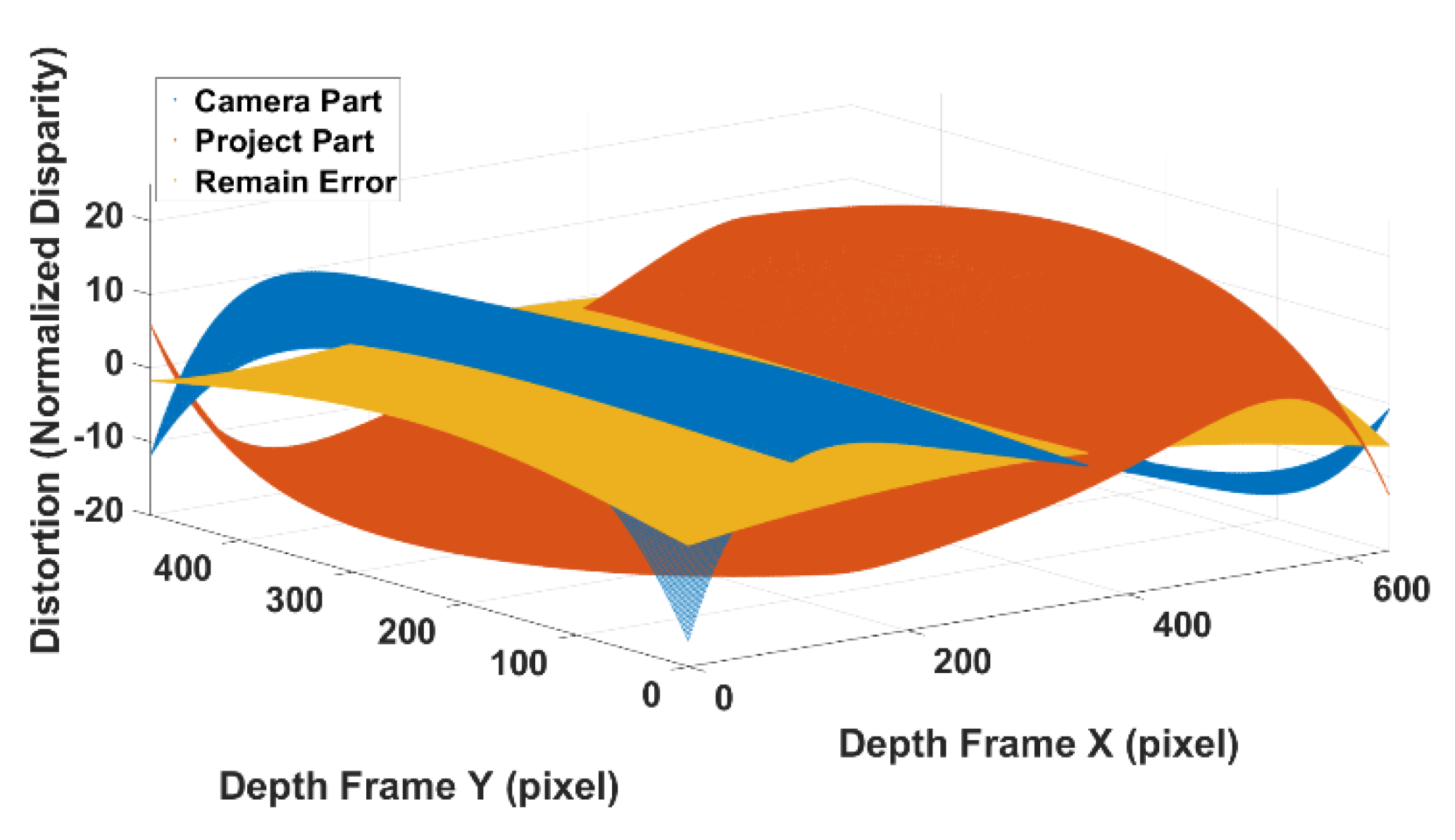
Therefore, for the SLP-based RGBD sensor, the distortion error in disparity consists of two parts, one is a barrel distortion caused by camera lens with fixed location at optical centre. The other is pincushion distortion caused by the projector lens with a varying location over the camera image plane. In practice, since the actual distance of projector to the object scene is often unknown, the proposed calibration model uses the measured distance in Equation (8) to calculate the distortion centre as an alternative.
5. Conclusions and Future Work
The RGBD sensor has a promising future to replace the high-cost 3D laser scanner and be applied in high-precision applications such as robotics, high-precision localization and mapping. The radial systematic error in the depth frame significantly limits its potential applications. Targeting this problem, this paper presented range-independent disparity-based calibration method for the SLP RGDB sensor. By revealing the real cause and forming mechanism of the non-centrosymmetric depth distortion, the proposed calibration method targets the disparity unit rather than the depth. By applying the calibration model in disparity and calculating the calibrated depth based on the calibrated disparity, the calibration model is independent of distance. No additional distance-based calibration or parameters look up table is required for the proposed method. With only one model with 20 parameters, the proposed calibration method can provide a full range coverage for the SLP RGBD sensor. A new non-centrosymmetric distortion calibration model for the normalized disparity is proposed in this paper based on the discussion on the form of the mechanism of the SLP RGBD sensor distortion. The proposed non-centrosymmetric distortion model can significantly reduce the large offset in the edge area of the depth frame. Since the heavily distorted edge area now can be calibrated to a similar accuracy level to the central area, more usable and valid information can be extracted and used to benefit applications such as SLAM, robotic exploration and obstacle avoidance. A new two-step calibration procedure is also developed in this paper to calibrate the barrel distortion caused by the IR camera lens, pincushion caused by the IR projector lens, and the systematic error caused by the IR cone.
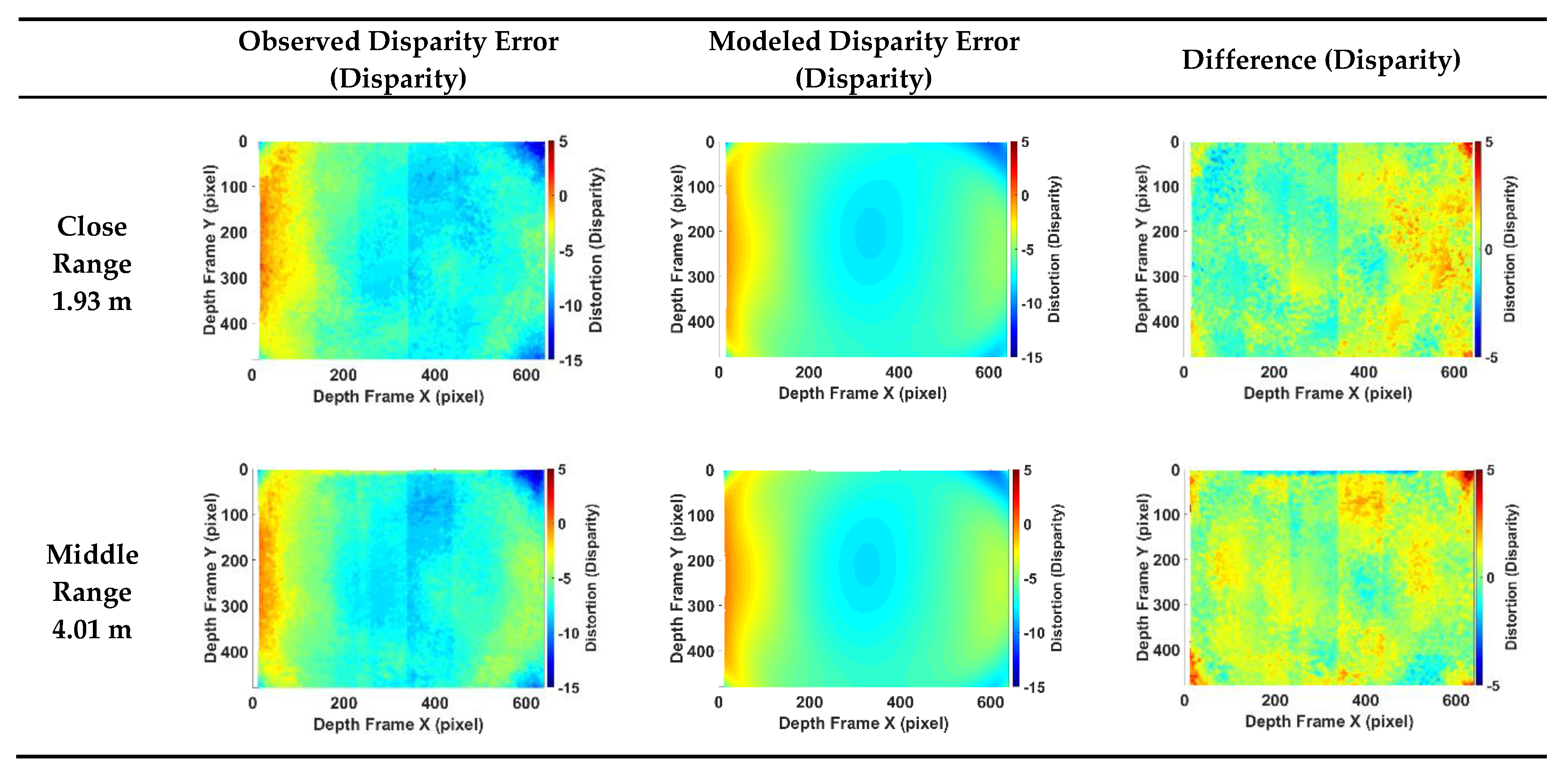
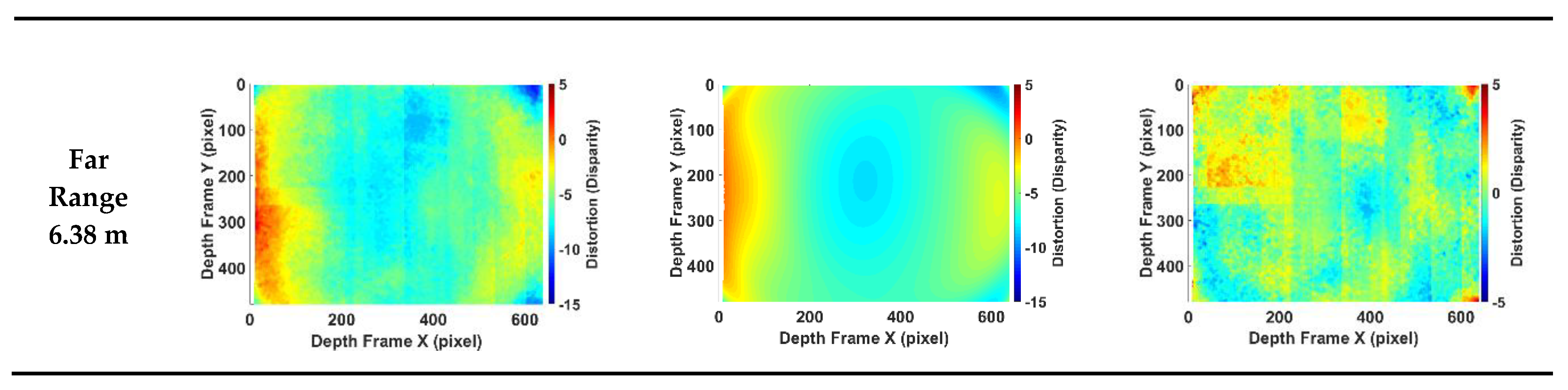
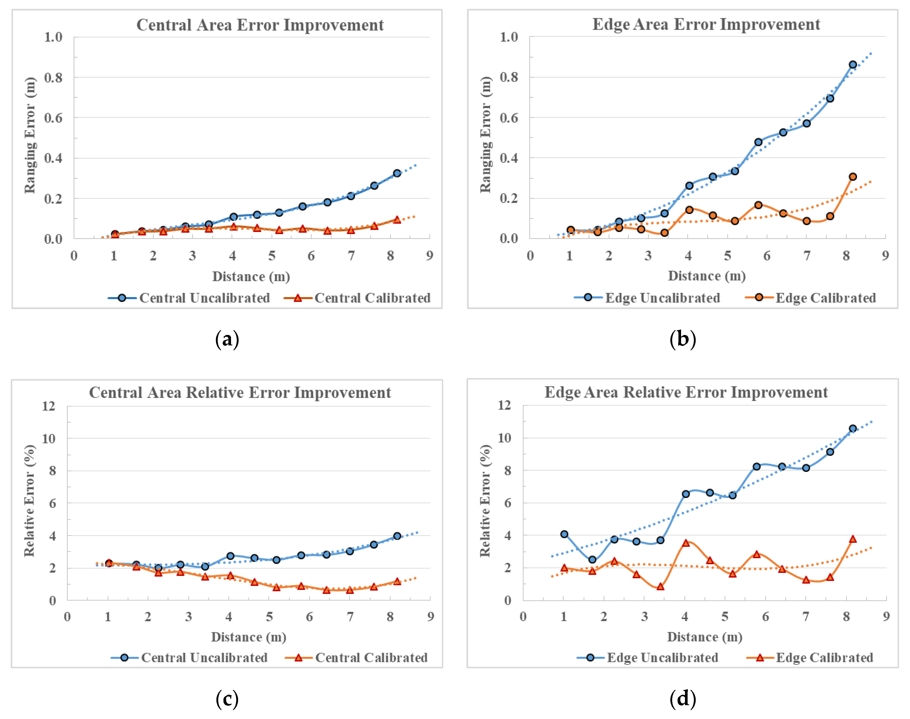
In the experimental results, the full frame and full-range coverage of the proposed calibration method is demonstrated. The comparison between the calibrated and uncalibrated point cloud clearly shows that the systematic errors in the measured point cloud have been removed by the calibration model. The significant offset in the edge area of long-range depth is reduced by the proposed model from 86 cm to 30 cm, which means that the relative error is reduced from 11% to 3% of the range distance. Overall, at far range the proposed calibration method can improve the depth accuracy by 70% in the central region of depth frame and 65% in the edge region.
Further work will study the long-term stability of calibration parameters for the consumer-grade RGBD sensor. Other potential systematic error sources, such as illumination condition, temperature, humidity, and air refractive index, will be investigated for a more comprehensive calibration model.


