A Three-dimensional Finger Motion Measurement System of a Thumb and an Index Finger Without a Calibration Process


Abstract
1. Introduction
2. Description of the Proposed System
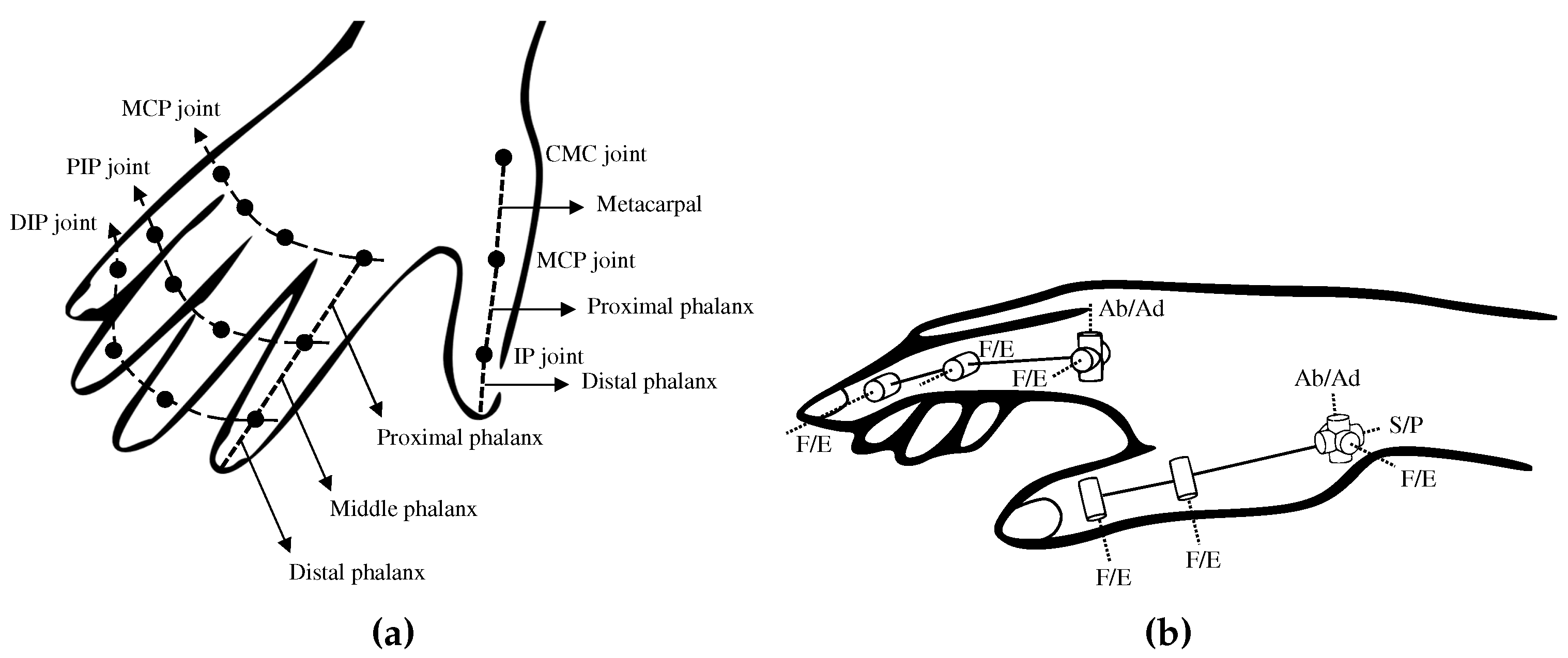
2.1. Characteristics of a Hand
2.2. Overview
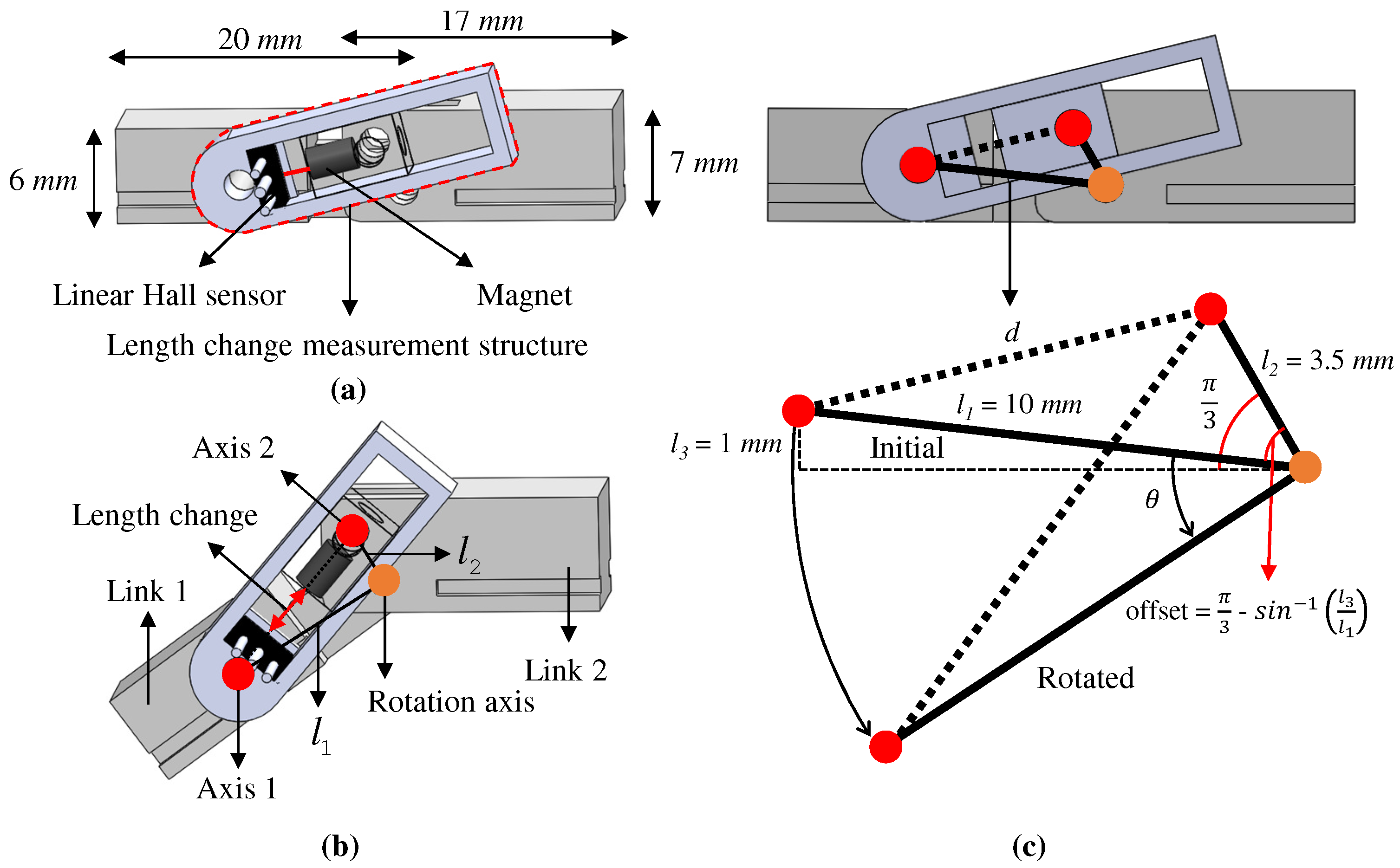
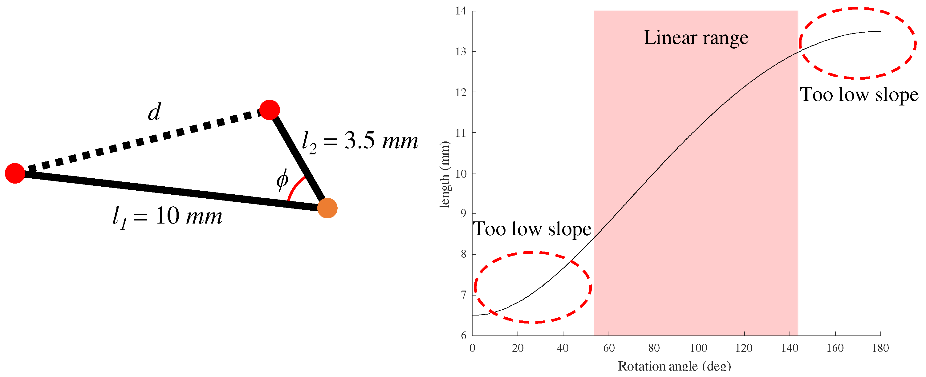
3. Hand Motion Measurement
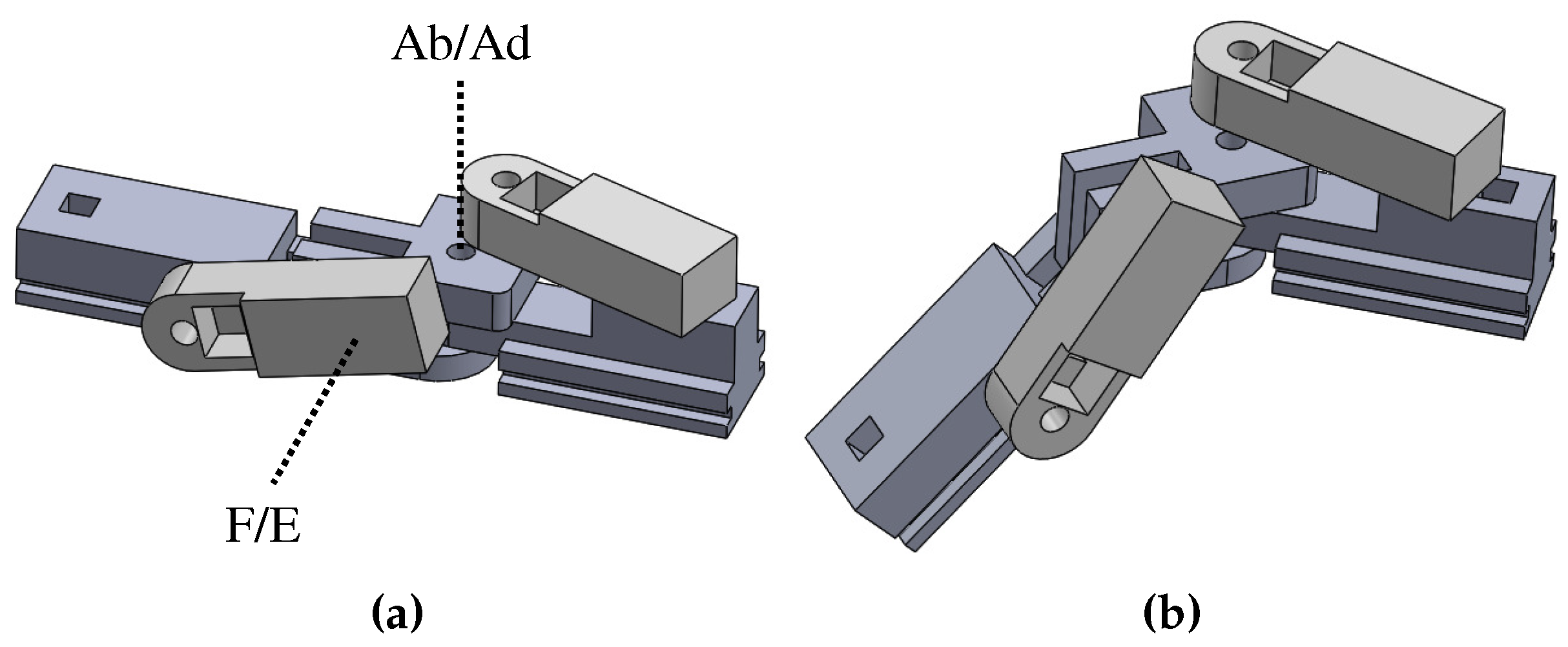
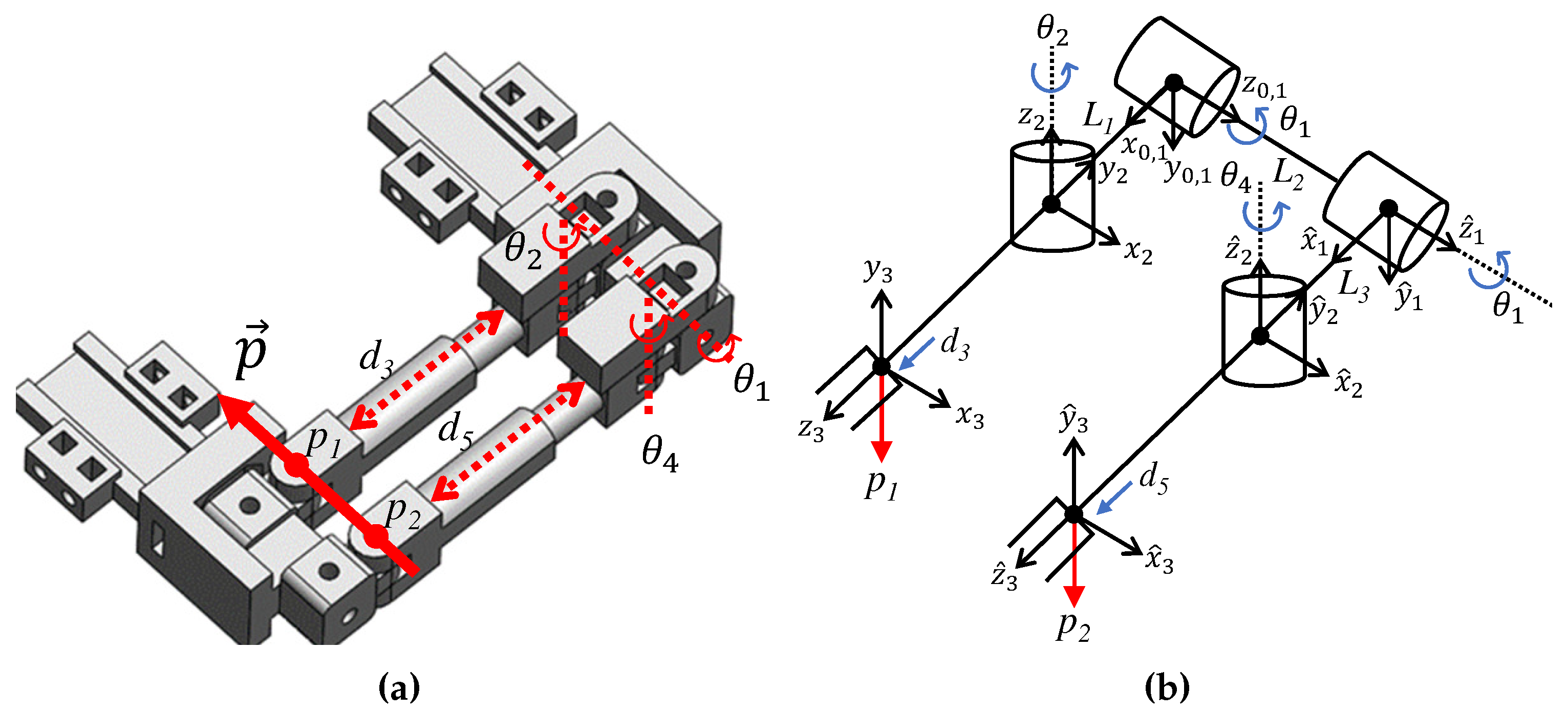
3.1. An Index Finger
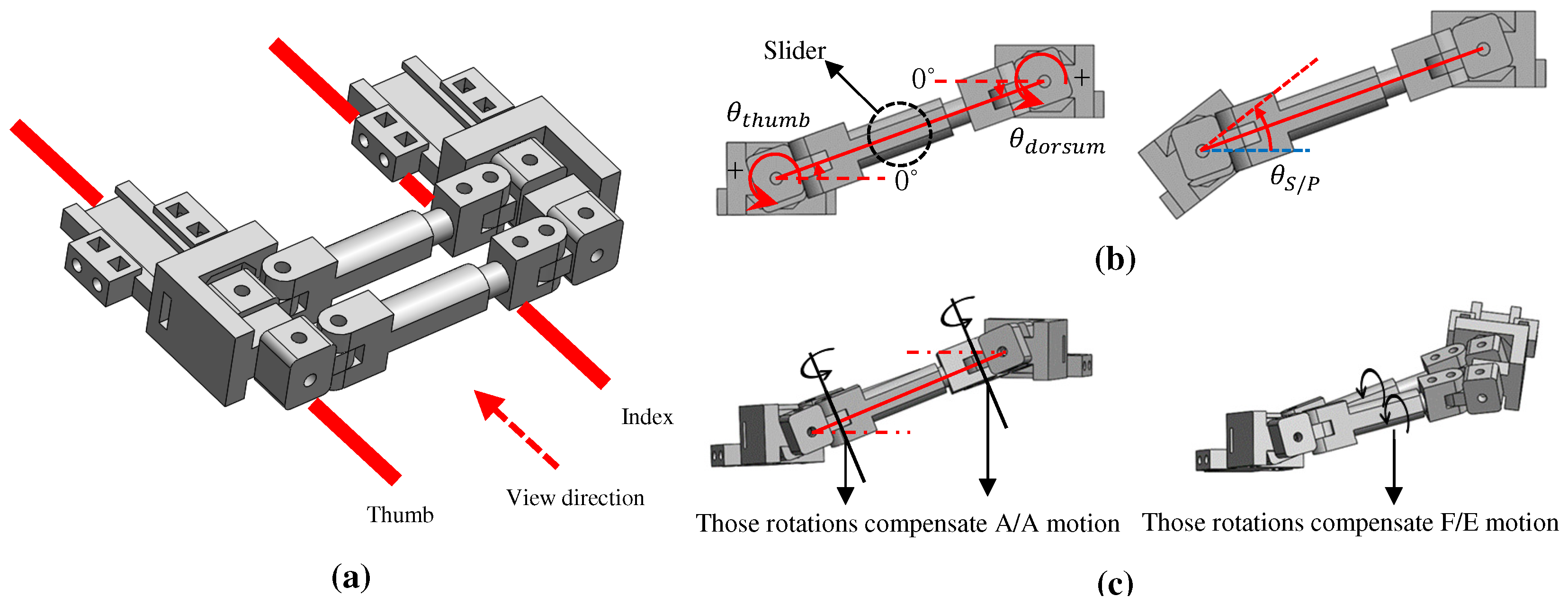
3.2. A Thumb
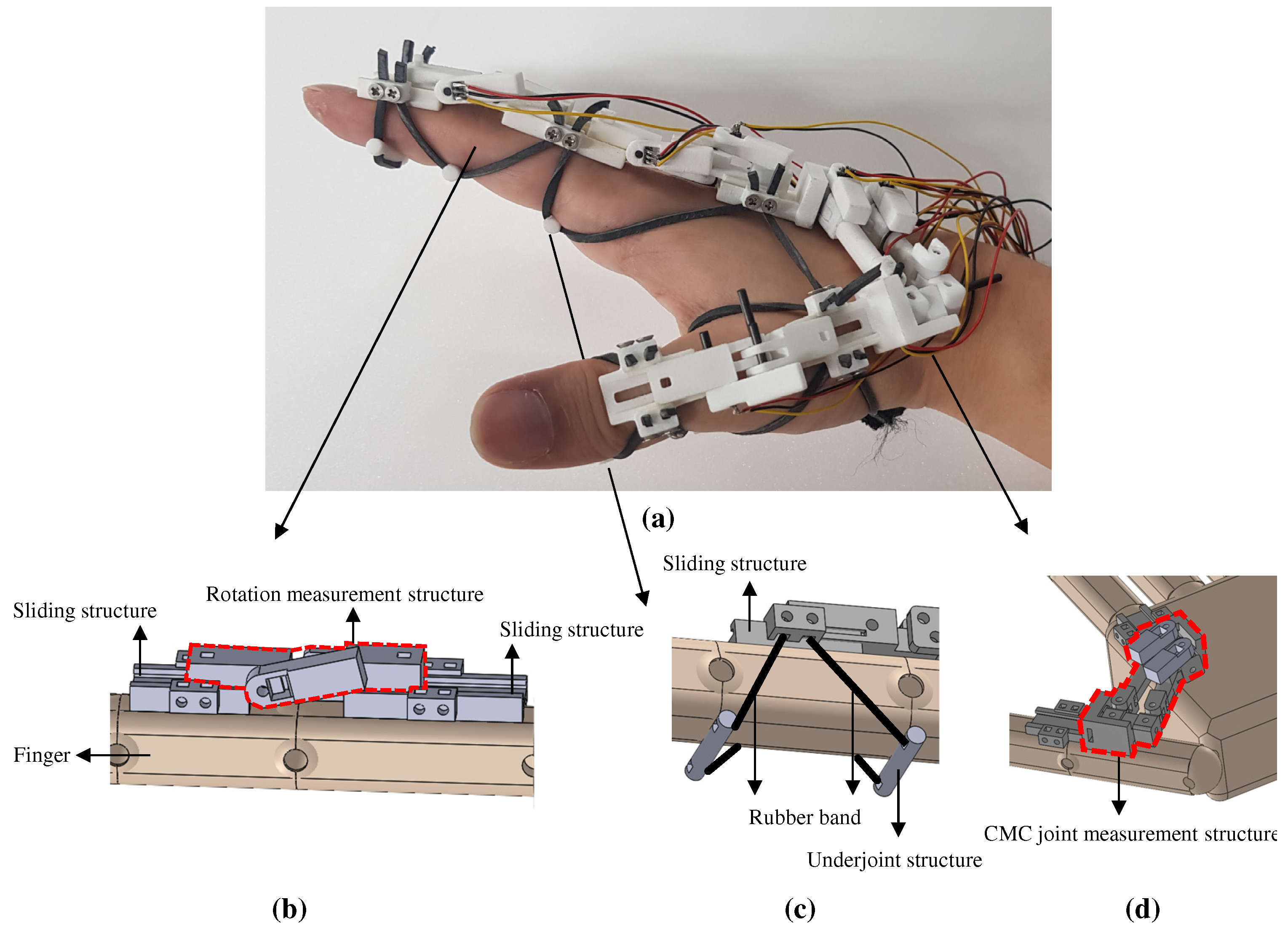
4. Wearing Method
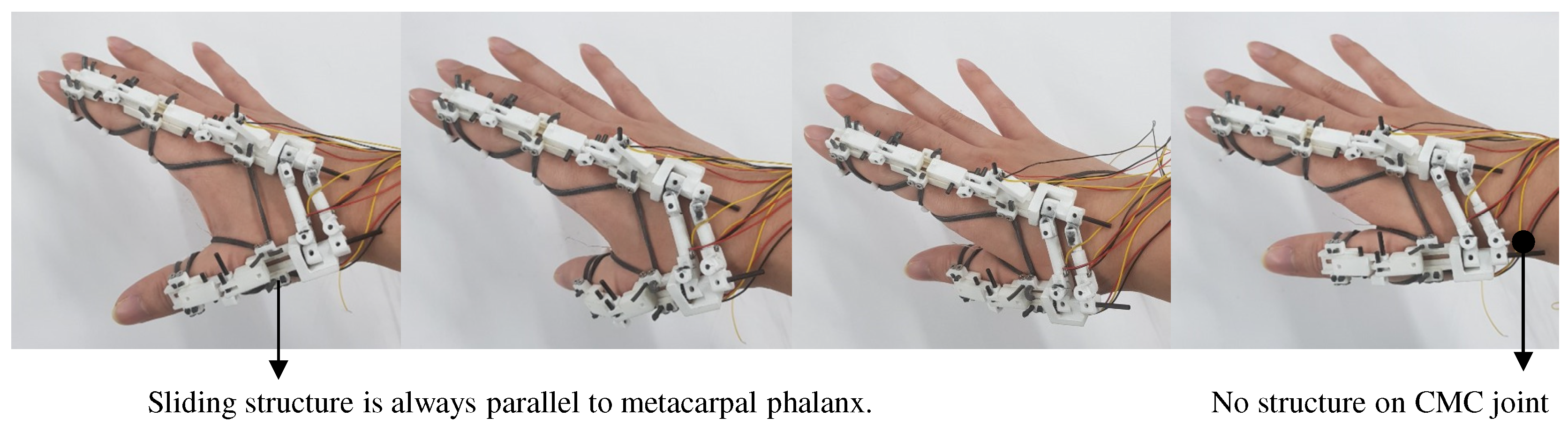
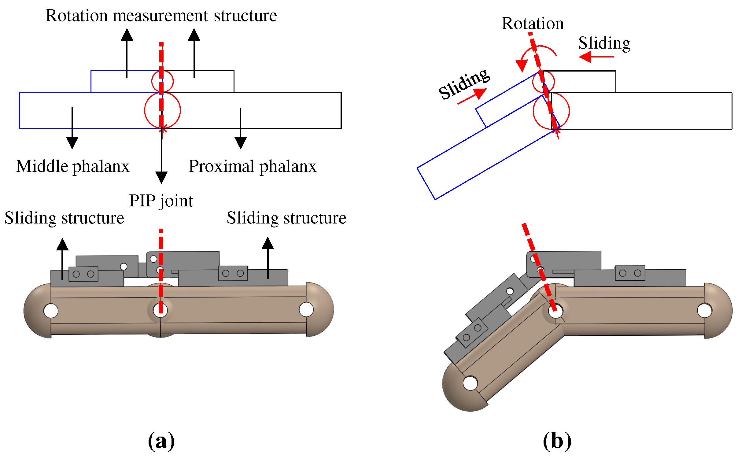
4.1. A Sliding Structure
4.2. An Underjoint Structure and a Rubber Band
5. Performance Verification
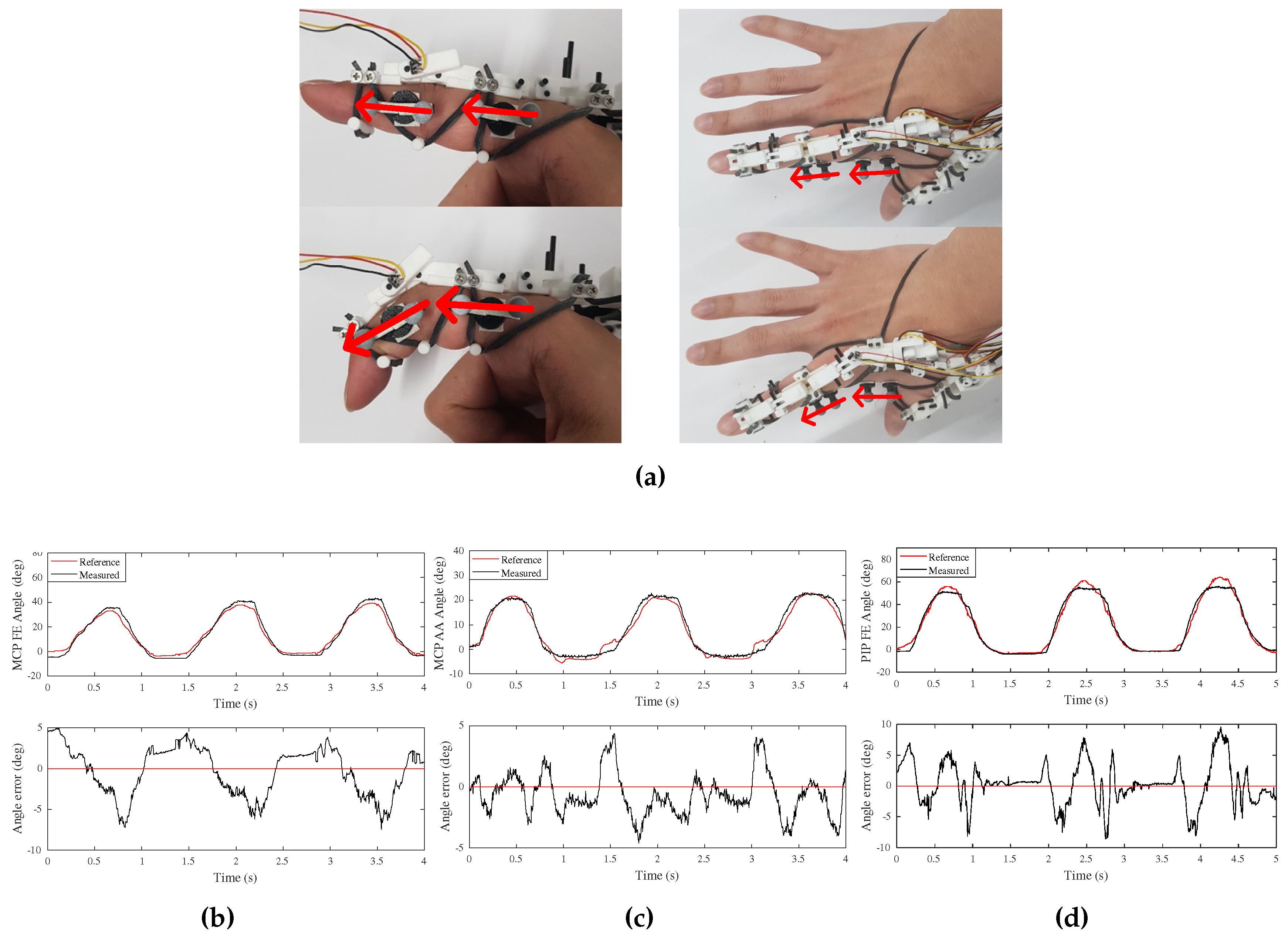
5.1. The Index Finger
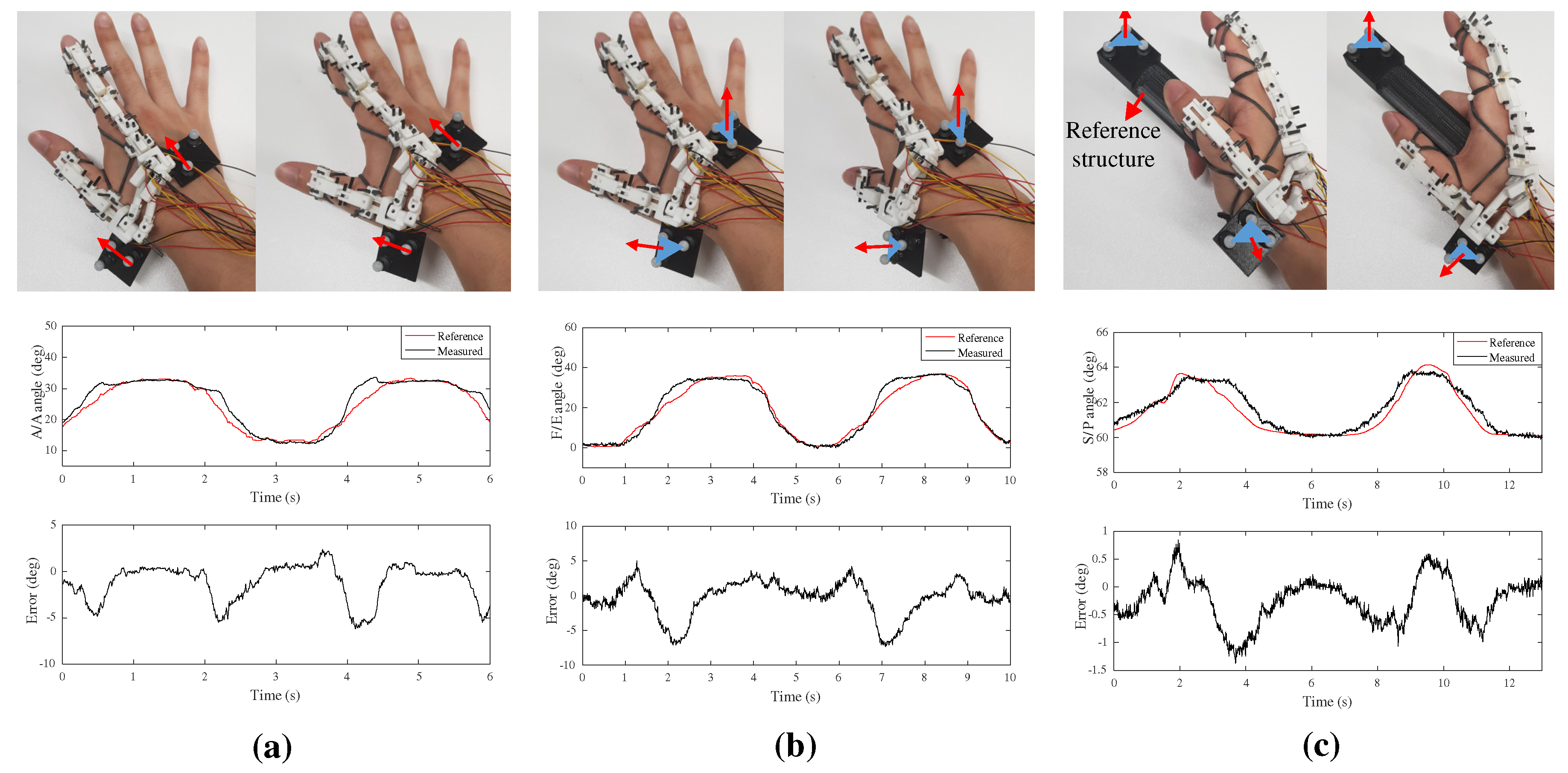
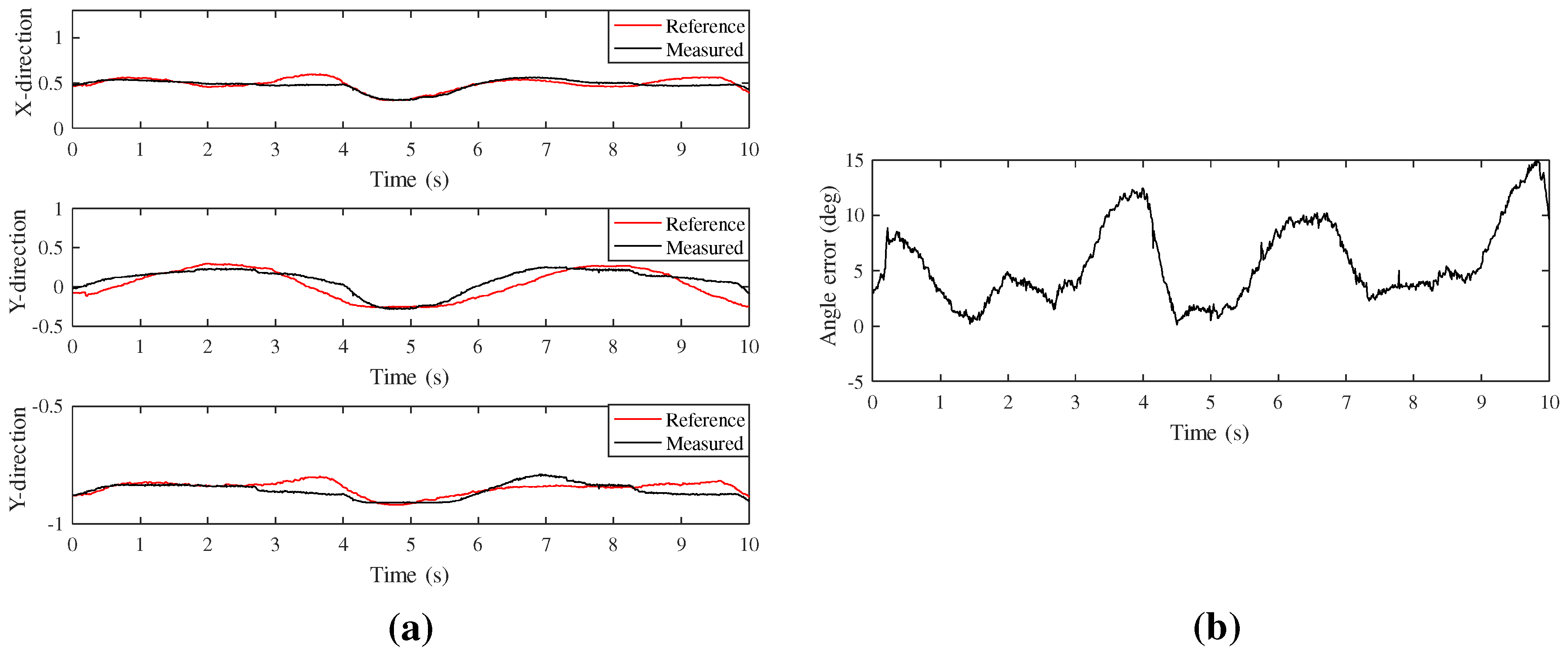
5.2. CMC Joint of the Thumb
6. Conclusions and Future Works
Author Contributions
Funding
Conflicts of Interest
References
- Hillebrand, G.; Bauer, M.; Achatz, K.; Klinker, G. Inverse kinematic infrared optical finger tracking. In Proceedings of the 9th International Conference on Humans and Computers (HC 2006), Copenhagen, Denmark, 1–6 October 2006; pp. 1–6. [Google Scholar]
- Han, S.; Liu, B.; Wang, R.; Ye, Y.; Twigg, C.D.; Kin, K. Online Optical Marker-based Hand Tracking with Deep Labels. ACM Trans. Graph. 2018, 37, 166. [Google Scholar] [CrossRef]
- Hoyet, L.; Ryall, K.; McDonnell, R.; O’Sullivan, C. Sleight of hand: Perception of finger motion from reduced marker sets. In Proceedings of the ACM SIGGRAPH Symposium on Interactive 3D Graphics and Games, Rennes, France, 15–17 November 2012; pp. 79–86. [Google Scholar]
- Optitrack. Prime 13. Available online: http://optitrack.com/ (accessed on 23 November 2019).
- VICON. Vicon Motion Systems Ltd. Available online: https://www.vicon.com/ (accessed on 23 November 2019).
- Noitom. Perception Neuron. Available online: https://www.neuronmocap.com/ (accessed on 23 November 2019).
- LEAP Motion. The Leap Motion Controller. Available online: https://www.leapmotion.com/ (accessed on 23 November 2019).
- Lu, W.; Tong, Z.; Chu, J. Dynamic hand gesture recognition with leap motion controller. IEEE Signal Process. Lett. 2016, 23, 1188–1192. [Google Scholar] [CrossRef]
- CyberGlove Systems. CyberGlove II. Available online: http://www.cyberglovesystems.com/ (accessed on 23 November 2019).
- Keller, G.D.; Hodges, L.F.; Walker, N. Evaluation of the CyberGlove as a whole-handwhole-hand input device. ACM Trans. Comput. Hum. Interact. 1995, 2, 263–283. [Google Scholar]
- Park, W.; Ro, K.; Kim, S.; Bae, J. A Soft Sensor-Based Three-Dimensional (3-D) Finger Motion Measurement System. Sensors 2017, 17, 420. [Google Scholar] [CrossRef] [PubMed]
- Li, K.; Chen, I.M.; Yeo, S.H.; Lim, C.K. Development of finger-motion capturing device based on optical linear encoder. J Rehabil. Res Dev. 2011, 48, 69–82. [Google Scholar] [CrossRef] [PubMed]
- Park, Y.; Lee, J.; Bae, J. Development of a Wearable Sensing Glove for Measuring the Motion of Fingers Using Linear Potentiometers and Flexible Wires. IEEE Trans. on Ind. Inform. 2015, 11, 198–206. [Google Scholar] [CrossRef]
- Gracia-Ibáñez, V.; Vergara, M.; Buffi, J.H.; Murray, W.M.; Sancho-Bru, J.L. Across-subject calibration of an instrumented glove to measure hand movement for clinical purposes. Comput. Methods Biomech. Biomed. Eng. 2017, 20, 587–597. [Google Scholar] [CrossRef] [PubMed]
- Kim, D.H.; Lee, S.W.; Park, H.S. Improving Kinematic Accuracy of Soft Wearable Data Gloves by Optimizing Sensor Locations. Sensors 2016, 16, 766. [Google Scholar] [CrossRef] [PubMed]
- Quam, D.L.; Williams, G.B.; Agnew, J.R.; Browne, P.C. An Experimental Determination of Human Hand Accuracy with a DataGlove. Hum. Factors Soc. Annu. Meet. 1989, 33, 315–319. [Google Scholar] [CrossRef]
- Hollister, A.; Buford, W.L.; Myers, L.M.; Giurintano, D.J.; Novick, A. The axes of rotation of the thumb carpometacarpal joint. J. Orthop. Res. 1992, 10, 454–460. [Google Scholar] [CrossRef] [PubMed]
- Neumann, D.; Rowan, E. Kinesiology of the Musculoskeletal System: Foundations for Physical Rehabilitation; Mosby: Philadelphia, PA, USA, 2002. [Google Scholar]
- Baln, G.I.; Polites, N.; Higgs, B.G.; Heptinstall, R.J.; McGrath, A.M. The functional range of motion of the finger joints. J. Hand Surg. 2015, 40, 406–411. [Google Scholar]
- Bullock, I.M.; Borràs, J.; Dollar, A.M. Assessing assumptions in kinematic hand models: A review. In Proceedings of the IEEE RAS & EMBS International Conference on Biomedical Robotics and Biomechatronics (BioRob), Rome, Italy, 24–27 June 2012; pp. 139–146. [Google Scholar]
- Chang, L.Y.; Pollard, N.S. Method for determining kinematic parameters of the in vivo thumb carpometacarpal joint. IEEE Trans. Biomed. Eng. 2008, 55, 1897–1906. [Google Scholar] [CrossRef] [PubMed]
- Hollister, A.; Giurintano, D.J. Thumb Movements, Motions, and Moments. J. Hand Ther. 1995, 8, 106–114. [Google Scholar] [CrossRef]
- Valero-Cuevasa, F.J.; Johansonc, M.E.; Towlesc, J.D. Towards a realistic biomechanical model of the thumb: The choice of kinematic description may be more critical than the solution method or the variability/uncertainty of musculoskeletal parameters. J. Biomech. 2003, 36, 1019–1030. [Google Scholar] [CrossRef]
- Cooney, W.P.; Lucca, M.J.; Chao, E.Y.S.; Linscheid, R.L. The kinesiology of the thumb trapeziometacarpal joint. J. Bone Jt. Surg. 1981, 63, 1371–1381. [Google Scholar] [CrossRef]
- DirSci, M.N.; Frankel, V.H. Basic Biomechanics of the Musculoskeletal System; Lippincott Williams & Wilkins: Philadelphia, PA, USA, 2001. [Google Scholar]
- Tan, H.Z.; Srinivasan, M.A.; Eberman, B.; Cheng, B. Human factors for the design of force-reflecting haptic interfaces. Dyn. Syst. Control 1994, 55, 353–359. [Google Scholar]


| i | ||||
|---|---|---|---|---|
| 1 | 0 | 0 | 0 | |
| 2 | 0 | |||
| 3 | 0 | 0 |
| i | ||||
|---|---|---|---|---|
| 1 | 0 | 0 | ||
| 2 | 0 | |||
| 3 | 0 | 0 |
| Sub1 | Sub2 | Sub3 | ||
|---|---|---|---|---|
| Width, Height, Length (mm) | 17, 18, 85 | 17, 18, 90 | 23, 23, 100 | |
| RMSE () | F/E of PIP | 2.45 | 3.37 | 2.68 |
| F/E of MCP | 1.84 | 2.94 | 2.34 | |
| Ab/Ad of MCP | 2.78 | 1.72 | 1.11 | |
© 2020 by the authors. Licensee MDPI, Basel, Switzerland. This article is an open access article distributed under the terms and conditions of the Creative Commons Attribution (CC BY) license (http://creativecommons.org/licenses/by/4.0/).
Share and Cite
Park, Y.; Bae, J. A Three-dimensional Finger Motion Measurement System of a Thumb and an Index Finger Without a Calibration Process. Sensors 2020, 20, 756. https://doi.org/10.3390/s20030756
Park Y, Bae J. A Three-dimensional Finger Motion Measurement System of a Thumb and an Index Finger Without a Calibration Process. Sensors. 2020; 20(3):756. https://doi.org/10.3390/s20030756
Chicago/Turabian StylePark, Yeongyu, and Joonbum Bae. 2020. "A Three-dimensional Finger Motion Measurement System of a Thumb and an Index Finger Without a Calibration Process" Sensors 20, no. 3: 756. https://doi.org/10.3390/s20030756
APA StylePark, Y., & Bae, J. (2020). A Three-dimensional Finger Motion Measurement System of a Thumb and an Index Finger Without a Calibration Process. Sensors, 20(3), 756. https://doi.org/10.3390/s20030756