DYSKIMOT: An Ultra-Low-Cost Inertial Sensor to Assess Head’s Rotational Kinematics in Adults during the Didren-Laser Test

 , ,
, ,  ,
, 
Abstract
:1. Introduction
2. Materials and Methods
2.1. Participants
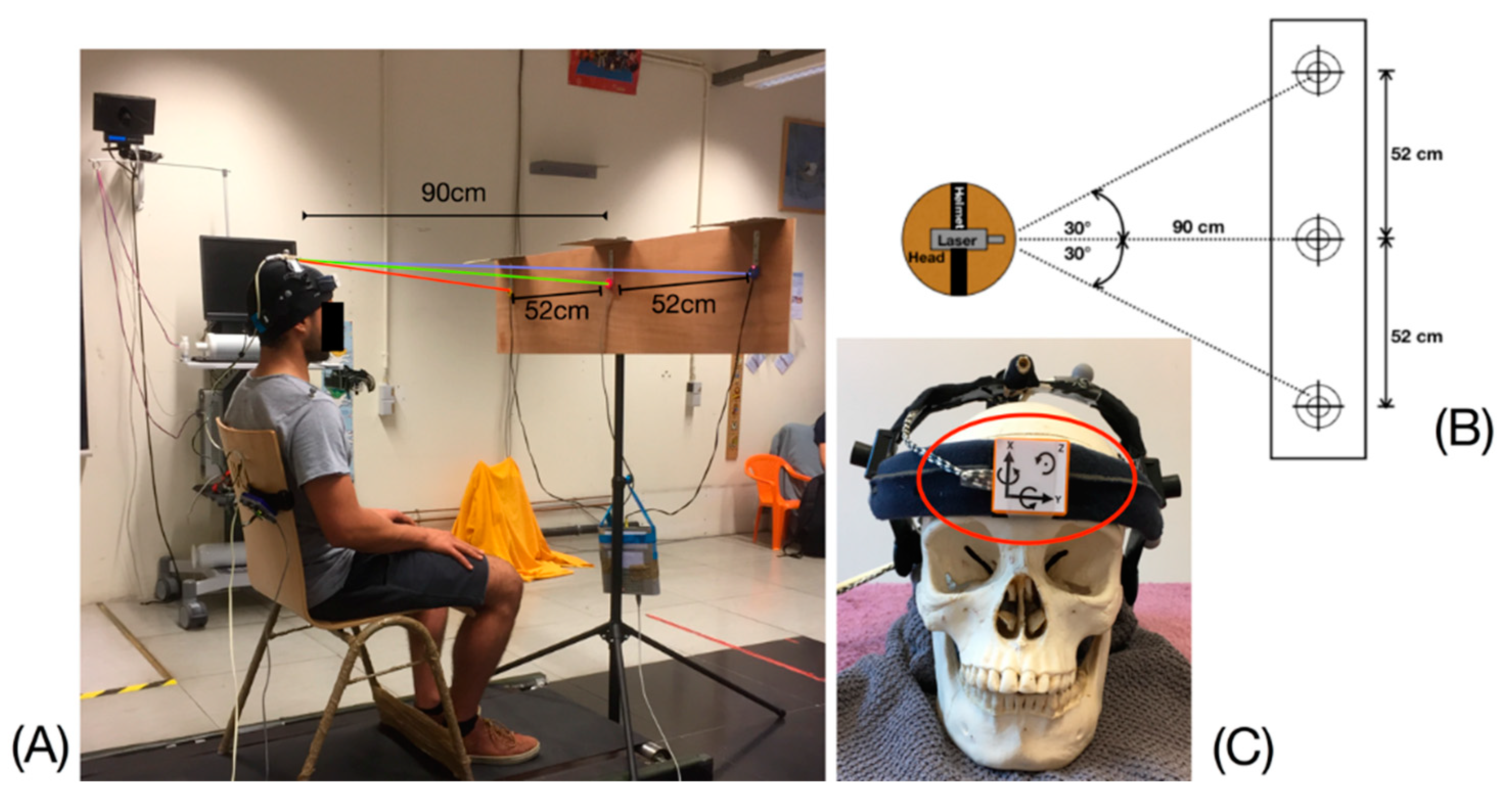
2.2. The DidRen Laser Test
2.3. Motion Sensors
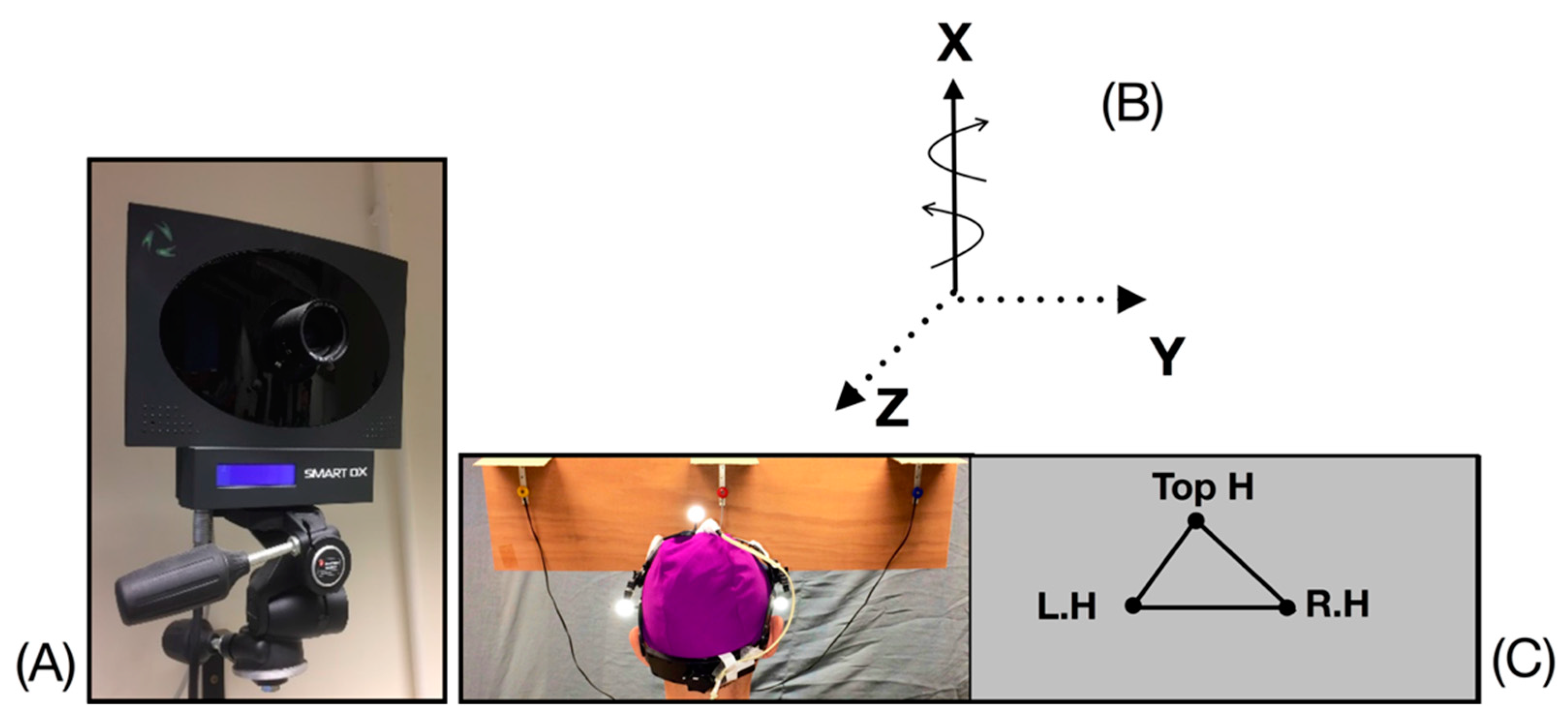
2.3.1. Elite System (BTS)
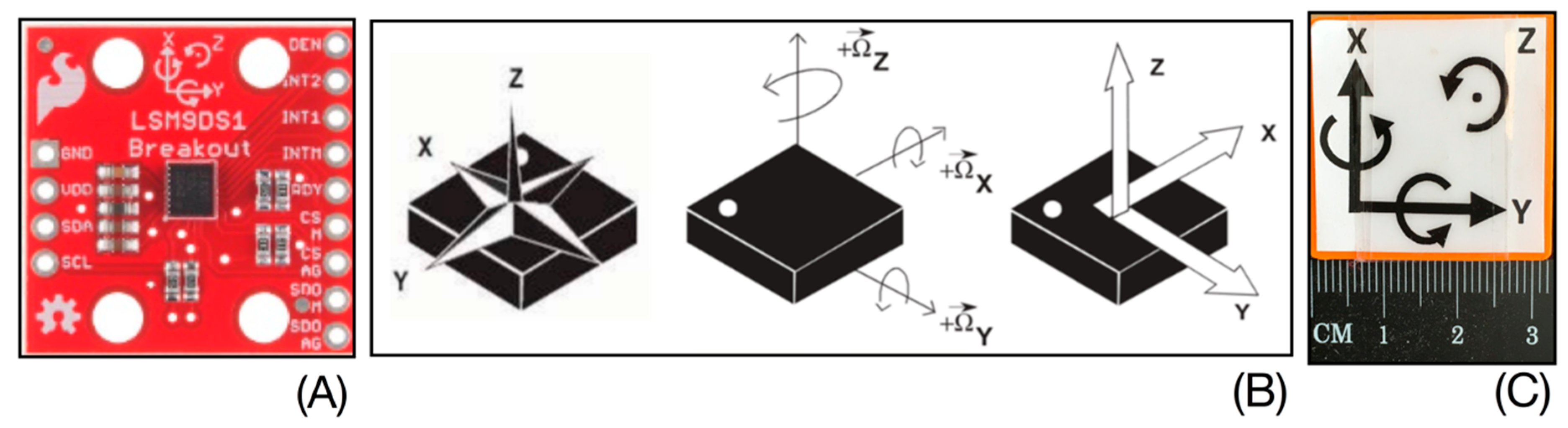
2.3.2. DYSKIMOT
2.4. Data Analysis
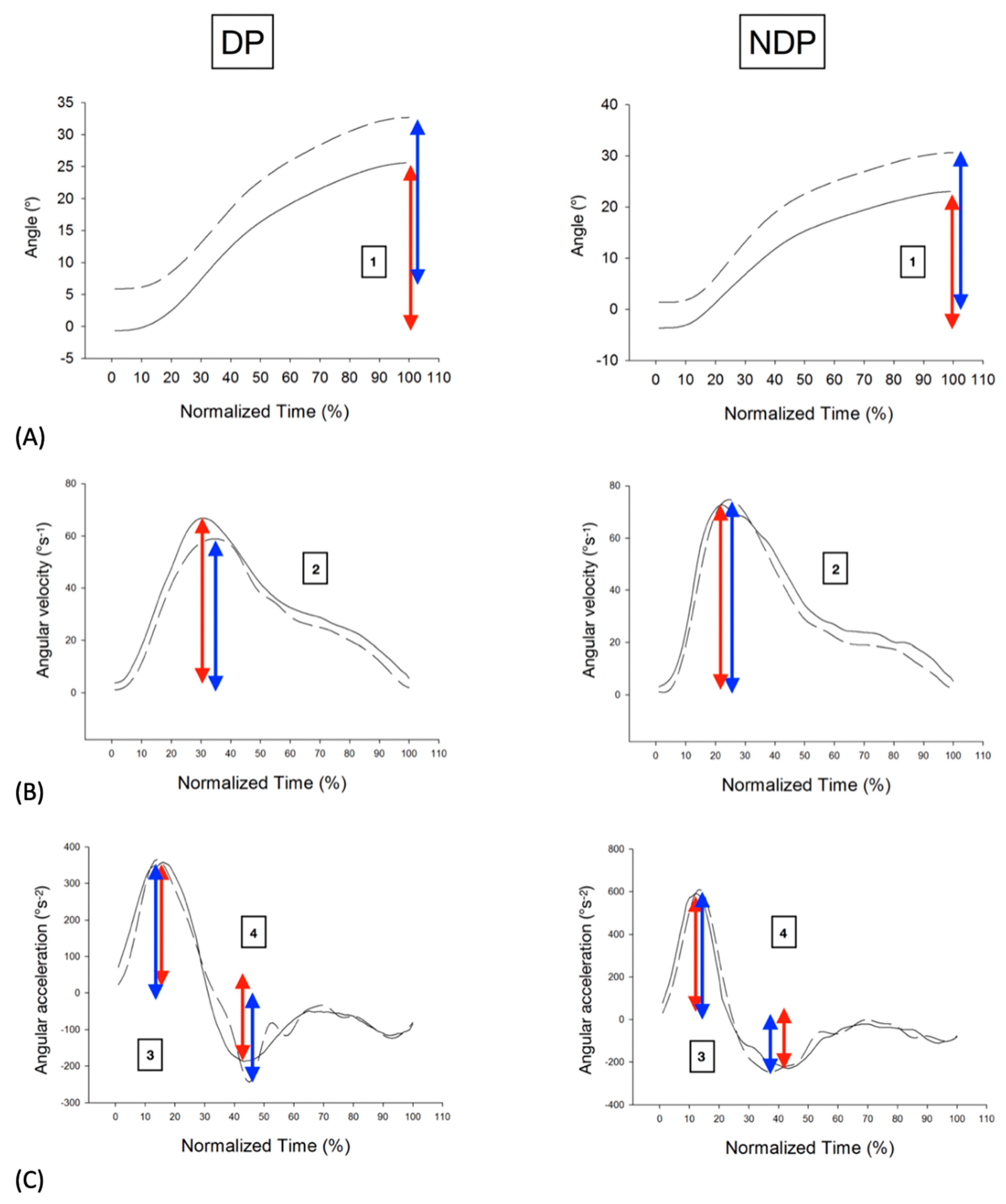
3. Results
4. Discussion
Author Contributions
Funding
Acknowledgments
Conflicts of Interest
References
- Blanpied, P.R.; Gross, A.R.; Elliott, J.M.; Devaney, L.L.; Clewley, D.; Walton, D.M.; Sparks, C.; Robertson, E.K. Neck Pain: Revision 2017. J. Orthop. Sport. Phys. Ther. 2017, 47, A1–A83. [Google Scholar] [CrossRef] [PubMed] [Green Version]
- Vos, T.; Barber, R.M.; Bell, B.; Bertozzi-Villa, A.; Biryukov, S.; Bolliger, I.; Charlson, F.; Davis, A.; Degenhardt, L.; Dicker, D.; et al. Global, regional, and national incidence, prevalence, and years lived with disability for 301 acute and chronic diseases and injuries in 188 countries, 1990–2013: A systematic analysis for the Global Burden of Disease Study 2013. Lancet 2015, 386, 743–800. [Google Scholar] [CrossRef] [Green Version]
- Coulter, I.D.; Crawford, C.; Vernon, H.; Hurwitz, E.L.; Khorsan, R.; Booth, M.S.; Herman, P.M. Manipulation and Mobilization for Treating Chronic Nonspecific Neck Pain: A Systematic Review and Meta-Analysis for an Appropriateness Panel. Pain Physician 2019, 22, E55–E70. [Google Scholar] [PubMed]
- Bays, P.M.; Wolpert, D.M. Computational principles of sensorimotor control that minimize uncertainty and variability. J. Physiol. 2007, 578 Pt 2, 387–396. [Google Scholar] [CrossRef]
- Roijezon, U.; Djupsjobacka, M.; Bjorklund, M.; Hager-Ross, C.; Grip, H.; Liebermann, D.G. Kinematics of fast cervical rotations in persons with chronic neck pain: A cross-sectional and reliability study. BMC Musculoskelet. Disord. 2010, 11, 222. [Google Scholar] [CrossRef] [Green Version]
- Sjolander, P.; Michaelson, P.; Jaric, S.; Djupsjobacka, M. Sensorimotor disturbances in chronic neck pain--range of motion, peak velocity, smoothness of movement, and repositioning acuity. Man. Ther. 2008, 13, 122–131. [Google Scholar] [CrossRef]
- Stenneberg, M.S.; Rood, M.; de Bie, R.; Schmitt, M.A.; Cattrysse, E.; Scholten-Peeters, G.G. To What Degree Does Active Cervical Range of Motion Differ Between Patients With Neck Pain, Patients With Whiplash, and Those Without Neck Pain? A Systematic Review and Meta-Analysis. Arch. Phys. Med. Rehabil. 2017, 98, 1407–1434. [Google Scholar] [CrossRef] [PubMed]
- Lemeunier, N.; Jeoun, E.B.; Suri, M.; Tuff, T.; Shearer, H.; Mior, S.; Wong, J.J.; da Silva-Oolup, S.; Torres, P.; D’Silva, C.; et al. Reliability and validity of clinical tests to assess posture, pain location, and cervical spine mobility in adults with neck pain and its associated disorders: Part 4. A systematic review from the cervical assessment and diagnosis research evaluation (CADRE) collaboration. Musculoskelet. Sci. Pract. 2018, 38, 128–147. [Google Scholar] [CrossRef]
- Youdas, J.W.; Carey, J.R.; Garrett, T.R. Reliability of measurements of cervical spine range of motion-comparison of three methods. Phys. Ther. 1991, 71, 98–104. [Google Scholar] [CrossRef]
- Bonnechere, B.; Salvia, P.; Dugailly, P.M.; Maroye, L.; Van Geyt, B.; Feipel, V. Influence of movement speed on cervical range of motion. Eur. Spine J. 2014, 23, 1688–1693. [Google Scholar] [CrossRef]
- Treleaven, J. Dizziness, Unsteadiness, Visual Disturbances, and Sensorimotor Control in Traumatic Neck Pain. J. Orthop. Sport. Phys. Ther. 2017, 47, 492–502. [Google Scholar] [CrossRef]
- de Zoete, R.M.; Osmotherly, P.G.; Rivett, D.A.; Farrell, S.F.; Snodgrass, S.J. Sensorimotor control in individuals with idiopathic neck pain and healthy individuals: A systematic review and meta-analysis. Arch. Phys. Med. Rehabil. 2016. [Google Scholar] [CrossRef]
- Roijezon, U.; Clark, N.C.; Treleaven, J. Proprioception in musculoskeletal rehabilitation. Part 1: Basic science and principles of assessment and clinical interventions. Man. Ther. 2015, 20, 368–377. [Google Scholar] [CrossRef] [PubMed]
- Sarig Bahat, H.; Weiss, P.L.; Sprecher, E.; Krasovsky, A.; Laufer, Y. Do neck kinematics correlate with pain intensity, neck disability or with fear of motion? Man. Ther. 2014, 19, 252–258. [Google Scholar] [CrossRef]
- Dugailly, P.M.; Coucke, A.; Salem, W.; Feipel, V. Assessment of cervical stiffness in axial rotation among chronic neck pain patients: A trial in the framework of a non-manipulative osteopathic management. Clin. Biomech. 2018, 53, 65–71. [Google Scholar] [CrossRef] [PubMed]
- Dugailly, P.M.; De Santis, R.; Tits, M.; Sobczak, S.; Vigne, A.; Feipel, V. Head repositioning accuracy in patients with neck pain and asymptomatic subjects: Concurrent validity, influence of motion speed, motion direction and target distance. Eur. Spine J. 2015, 24, 2885–2891. [Google Scholar] [CrossRef]
- Michiels, S.; Hallemans, A.; Van de Heyning, P.; Truijen, S.; Stassijns, G.; Wuyts, F.; De Hertogh, W. Measurement of cervical sensorimotor control: The reliability of a continuous linear movement test. Man. Ther. 2014, 19, 399–404. [Google Scholar] [CrossRef]
- Hage, R.; Dierick, F.; Roussel, N.; Pitance, L.; Detrembleur, C. Age-related kinematic performance should be considered during fast head-neck rotation target task in individuals aged from 8 to 85 years old. PeerJ 2019, 7, e7095. [Google Scholar] [CrossRef]
- Nagai, T.; Clark, N.C.; Abt, J.P.; Sell, T.C.; Heebner, N.R.; Smalley, B.W.; Wirt, M.D.; Lephart, S.M. The Effect of Target Position on the Accuracy of Cervical-Spine-Rotation Active Joint-Position Sense. J. Sport Rehabil. 2016, 25, 58–63. [Google Scholar] [CrossRef]
- Zhou, Y.; Loh, E.; Dickey, J.P.; Walton, D.M.; Trejos, A.L. Development of the circumduction metric for identification of cervical motion impairment. J. Rehabil. Assist. Technol. Eng. 2018, 5. [Google Scholar] [CrossRef]
- Willemsen, A.T.; van Alste, J.A.; Boom, H.B. Real-time gait assessment utilizing a new way of accelerometry. J. Biomech. 1990, 23, 859–863. [Google Scholar] [CrossRef] [Green Version]
- Picerno, P. 25 years of lower limb joint kinematics by using inertial and magnetic sensors: A review of methodological approaches. Gait Posture 2017, 51, 239–246. [Google Scholar] [CrossRef]
- Robert-Lachaine, X.; Mecheri, H.; Larue, C.; Plamondon, A. Validation of inertial measurement units with an optoelectronic system for whole-body motion analysis. Med. Biol. Eng. Comput. 2017, 55, 609–619. [Google Scholar] [CrossRef]
- Boissy, P.; Briere, S.; Hamel, M.; Jog, M.; Speechley, M.; Karelis, A.; Frank, J.; Vincent, C.; Edwards, R.; Duval, C. Wireless inertial measurement unit with GPS (WIMU-GPS)--wearable monitoring platform for ecological assessment of lifespace and mobility in aging and disease. In Proceedings of the 2011 Annual International Conference of the IEEE Engineering in Medicine and Biology Society IEEE Engineering in Medicine and Biology Society Annual Conference, Boston, MA, USA, 30 August–3 September 2011; pp. 5815–5819. [Google Scholar] [CrossRef]
- Szczesna, A.; Skurowski, P.; Lach, E.; Pruszowski, P.; Peszor, D.; Paszkuta, M.; Stupik, J.; Lebek, K.; Janiak, M.; Polanski, A.; et al. Inertial Motion Capture Costume Design Study. Sensors 2017, 17, 612. [Google Scholar] [CrossRef] [PubMed] [Green Version]
- Hage, R.; Ancenay, E. Identification of a relationship between cervical spine function and rotational movement control. Ann. Phys. Rehabil. Med. 2009, 52, 653–667. [Google Scholar] [CrossRef] [PubMed] [Green Version]
- Sarig Bahat, H.; Weiss, P.L.; Laufer, Y. The effect of neck pain on cervical kinematics, as assessed in a virtual environment. Arch. Phys. Med. Rehabil. 2010, 91, 1884–1890. [Google Scholar] [CrossRef]
- Hage, R.; Buisseret, F.; Pitance, L.; Brismee, J.M.; Detrembleur, C.; Dierick, F. Head-neck rotational movements using DidRen laser test indicate children and seniors’ lower performance. PLoS ONE 2019, 14, e0219515. [Google Scholar] [CrossRef]
- Vernon, H.; Mior, S. The Neck Disability Index: A study of reliability and validity. J. Manip. Physiol. Ther. 1991, 14, 409–415. [Google Scholar]
- Meisingset, I.; Stensdotter, A.K.; Woodhouse, A.; Vasseljen, O. Neck motion, motor control, pain and disability: A longitudinal study of associations in neck pain patients in physiotherapy treatment. Man. Ther. 2016, 22, 94–100. [Google Scholar] [CrossRef]
- Bulgheroni, M.V.; Antonaci, F.; Ghirmai, S.; Sandrini, G.; Nappi, G.; Pedotti, A. A 3D kinematic method for evaluating voluntary movements of the cervical spine in humans. Funct. Neurol. 1998, 13, 239–245. [Google Scholar]
- Davis, R.B., III; Õunpuu, S.; Tyburski, D.; Gage, J.R. A gait analysis data collection and reduction technique. Hum. Mov. Sci. 1991, 10, 575–587. [Google Scholar] [CrossRef]
- Theobald, P.S.; Jones, M.D.; Williams, J.M. Do inertial sensors represent a viable method to reliably measure cervical spine range of motion? Man. Ther. 2012, 17, 92–96. [Google Scholar] [CrossRef]
- Bilic-Zulle, L. Comparison of methods: Passing and Bablok regression. Biochem. Med. 2011, 21, 49–52. [Google Scholar] [CrossRef] [PubMed]
- Cuesta-Vargas, A.I.; Galan-Mercant, A.; Williams, J.M. The use of inertial sensors system for human motion analysis. Phys. Ther. Rev. 2010, 15, 462–473. [Google Scholar] [CrossRef] [PubMed] [Green Version]
- Duc, C.; Salvia, P.; Lubansu, A.; Feipel, V.; Aminian, K. A wearable inertial system to assess the cervical spine mobility: Comparison with an optoelectronic-based motion capture evaluation. Med. Eng. Phys. 2014, 36, 49–56. [Google Scholar] [CrossRef] [PubMed]
- Teufl, W.; Miezal, M.; Taetz, B.; Frohlich, M.; Bleser, G. Validity, Test-Retest Reliability and Long-Term Stability of Magnetometer Free Inertial Sensor Based 3D Joint Kinematics. Sensors 2018, 18, 1980. [Google Scholar] [CrossRef] [PubMed] [Green Version]
- Saber-Sheikh, K.; Bryant, E.C.; Glazzard, C.; Hamel, A.; Lee, R.Y. Feasibility of using inertial sensors to assess human movement. Man. Ther. 2010, 15, 122–125. [Google Scholar] [CrossRef]
- Bolink, S.A.; Naisas, H.; Senden, R.; Essers, H.; Heyligers, I.C.; Meijer, K.; Grimm, B. Validity of an inertial measurement unit to assess pelvic orientation angles during gait, sit-stand transfers and step-up transfers: Comparison with an optoelectronic motion capture system. Med. Eng. Phys. 2016, 38, 225–231. [Google Scholar] [CrossRef]
- Hage, R.; Lognoul, S.; Siméoni, A.; Fourré, A.; Detrembleur, C.; Dierick, F. An Ultra low-Cost Inertial Sensor is Able To Assess Neck’s Kinematics In Non-Disabled And Slighltly-Disabled Adults During The DidRen-Laser Test. In Proceedings of the Congrès ECMT Antwerpen, Antwerpen, Belgium, 20–21 September 2019. [Google Scholar]
- Fuhrman, C.; Chouaid, C. Concordance between two variables: Numerical approaches (qualitative observations—The kappa coefficient-; quantitative measures. Rev. des Mal. Respir. 2004, 21, 123–125. [Google Scholar] [CrossRef]
- Grenier, B.; Dubreuil, M.; Journois, D. Comparison of two measurement methods: the Bland and Altman assessment. Ann. Fr. D’anesth. et de Reanim. 2000, 19, 128–135. [Google Scholar] [CrossRef]
- Rosa, M.; Fugmann, E.; Pinto, G.; Nunes, M. An anchored dynamic time-warping for alignment and comparison of swallowing acoustic signals. In Proceedings of the 2017 Annual International Conference of the IEEE Engineering in Medicine and Biology Society IEEE Engineering in Medicine and Biology Society Annual Conference, Seogwipo, Korea, 11–15 July 2017; pp. 2749–2752. [Google Scholar] [CrossRef]
- Lee, H.S. Application of dynamic time warping algorithm for pattern similarity of gait. J. Exerc. Rehabil. 2019, 15, 526–530. [Google Scholar] [CrossRef] [PubMed] [Green Version]
- Yang, C.Y.; Chen, P.Y.; Wen, T.J.; Jan, G.E. IMU Consensus Exception Detection with Dynamic Time Warping-A Comparative Approach. Sensors 2019, 19, 2237. [Google Scholar] [CrossRef] [PubMed] [Green Version]
- Sarig Bahat, H.; Chen, X.; Reznik, D.; Kodesh, E.; Treleaven, J. Interactive cervical motion kinematics: Sensitivity, specificity and clinically significant values for identifying kinematic impairments in patients with chronic neck pain. Man. Ther. 2015, 20, 295–302. [Google Scholar] [CrossRef] [PubMed] [Green Version]
- de Zoete, R.M.J.; Osmotherly, P.G.; Rivett, D.A.; Snodgrass, S.J. No Differences Between Individuals With Chronic Idiopathic Neck Pain and Asymptomatic Individuals on Seven Cervical Sensorimotor Control Tests: A Cross-Sectional Study. J. Orthop. Sport. Phys. Ther. 2019, 1–37. [Google Scholar] [CrossRef] [PubMed]
- Tsang, S.M.; Szeto, G.P.; Lee, R.Y. Movement coordination and differential kinematics of the cervical and thoracic spines in people with chronic neck pain. Clin. Biomech. 2013, 28, 610–617. [Google Scholar] [CrossRef] [PubMed]


| NDP (n = 15) | DP (n = 9) | |
|---|---|---|
| Age (years) | 24 ± 3 | 31 ± 14 |
| Gender (men/women) | 12/3 | 5/4 |
| BMI (kg/m2) | 22.2 ± 2.7 | 21.8 ± 2.3 |
| NDI (%) | 0 [0–0] | 14 [10–16] |
| NPRS (/10) | 0 [0–0] | 3 [0–0] 1 |
| ANOVA | Difference of the Means (Dyskimot-Elite or DP-NDP) | p | |
|---|---|---|---|
| Angle (°) | System | 1.76 | <0.001 |
| Status | −0.398 | 0.157 | |
| System x Status | 0.094 | ||
| Average angular velocity (°s−1) | System | −5.50 | 0.022 |
| Status | 1.72 | 0.462 | |
| System x Status | 0.655 | ||
| Peak angular velocity (°s−1) | System | 5.74 | 0.498 |
| Status | 6.22 | 0.630 | |
| System x Status | 0.708 | ||
| Peak angular acceleration (°s−2) | System | 89.9 | 0.282 |
| Status | 59.8 | 0.473 | |
| System x Status | 0.880 | ||
| Peak angular deceleration (°s−2) | System | −81.3 | 0.261 |
| Status | −46.6 | 0.517 | |
| System x Status | 0.955 |
| Slope | Offset | r | |
|---|---|---|---|
| Angle (°) | 0.908 [−2.09, 1.86] | 4.34 [−20.6, 82.5] | 0.431 |
| Average angular velocity (°s−1) | 0.922 [0.713, 1.32] | −0.518 [−18.0, 7.57] | 0.694 |
| Peak angular velocity (°s−1) | 1.01 [0.942, 1.11] | 2.80 [−5.27, 10.2] | 0.906 |
| Peak angular acceleration (°s−2) | 1.10 [0.939, 1.20] | 7.71 [−50.4, 125] | 0.922 |
| Peak angular deceleration (°s−2) | 1.04 [0.906, 1.13] | 43.1 [−0.623, 131] | 0.918 |
| Elite | DYSKIMOT | ||
|---|---|---|---|
| Infrared digital cameras | 8 | MARG sensor | IMU LSM9DS1 |
| Resolution | 1.5 Mpixel | Gyrometer range | ±245 °/s |
| Sample frequency | 200 Hz | Sample frequency | 100 Hz |
| Accuracy/volume | <0.1 mm on 4 × 3 × 3 m | Gyrometer sensitivity | 8.75 10−3 °/s |
© 2020 by the authors. Licensee MDPI, Basel, Switzerland. This article is an open access article distributed under the terms and conditions of the Creative Commons Attribution (CC BY) license (http://creativecommons.org/licenses/by/4.0/).
Share and Cite
Hage, R.; Detrembleur, C.; Dierick, F.; Pitance, L.; Jojczyk, L.; Estievenart, W.; Buisseret, F. DYSKIMOT: An Ultra-Low-Cost Inertial Sensor to Assess Head’s Rotational Kinematics in Adults during the Didren-Laser Test. Sensors 2020, 20, 833. https://doi.org/10.3390/s20030833
Hage R, Detrembleur C, Dierick F, Pitance L, Jojczyk L, Estievenart W, Buisseret F. DYSKIMOT: An Ultra-Low-Cost Inertial Sensor to Assess Head’s Rotational Kinematics in Adults during the Didren-Laser Test. Sensors. 2020; 20(3):833. https://doi.org/10.3390/s20030833
Chicago/Turabian StyleHage, Renaud, Christine Detrembleur, Frédéric Dierick, Laurent Pitance, Laurent Jojczyk, Wesley Estievenart, and Fabien Buisseret. 2020. "DYSKIMOT: An Ultra-Low-Cost Inertial Sensor to Assess Head’s Rotational Kinematics in Adults during the Didren-Laser Test" Sensors 20, no. 3: 833. https://doi.org/10.3390/s20030833