Recent Advances in Indoor Localization via Visible Lights: A Survey


Abstract
:1. Introduction
2. Background on Visible Light Communication
- Low cost: LED photo-diodes are very cheap, ranging from less than a dollar to $3, while LED light bulbs are also much cheaper than fluorescent lights.
- High bandwidth: Recent efforts in VLC have been focusing on increasing the transmission bandwidth. In 2014, Tsonev et al. [27] presented a gallium nitride LED system, which could achieve the data rate of 3 GB/s.
- Low power consumption: LEDs are very power efficient light sources and, thus, an eco-friendly technology. Now, most of the consumers are switching to LEDs from fluorescent bulbs as LEDs give the same brightness for a cheaper price. If all the lights of the world could be replaced by LEDs, then the overall power consumption of the whole world would reduce drastically.
- High longevity: LEDs can live up to 10 years with a satisfactory amount of lighting [28].
3. Visible Light Indoor Localization
3.1. System Architecture and Common Processes
- Transmitter. In the transmitter, there is usually a microcontroller which controls the signal modulator to send certain signals to the light source (such as LED array) so that the light source can change its output. In some of the VLL systems, the transmitter part is simply the light source without any modification, while in the others, more complex control and signals are used for the modified light sources.
- Receiving Device. The receiving side generally has a photo-diode/camera to receive the light signal from the transmitter. The received signal is then passed to the signal demodulator. The localization algorithm uses the demodulated signal to find out the location.
- Phase 1. A packet data is first encoded into a binary sequence (which is a high–low voltage to control the intensity of light by on–off switching, also known as ON–OFF KEYING (OOK)). OOK is an intensity modulation, which is a prevalent method in VLC. More complex modulation can also be used.
- Phase 2. Line of Sight (LoS) paths are required from the light source to the receiver to transmit the data via VLC channels; otherwise, the system may suffer from degradation of signals resulting in a huge amount of inaccuracy.
- Phase 3. The final phase of the process is to find out the location of the receiver. The receiver receives the signal and then extracts its characteristics, which are required for the input of the localization algorithm. Some of the examples of these characteristics are Angle of Arrival (AoA), Received Signal Strength (RSS), and Time of Arrival (ToA). The receiver’s location could be known by running the algorithms on the extracted characteristics at the localization module.
- Subject is the receiver. This is the most common VLL setting, where the subject of localization is the receiver. For example, as shown in Figure 3a, the mobile user holds his smartphone, in which the camera acts as the receiver, and the location of the smartphone is calculated by the VLL system. Such a setting (or a similar setting where a photo-diode is attached to the subject instead of the smartphone’s camera) has been used in [42,43,44,45,46,47,48,49,50,51,52].
- Subject localized via reflection. Similar to the second scenario, the subject is not the receiver here since the light source and receiver are on the same side of the system (such as both are on the ceiling in Figure 3c). Thus, the localization is done by analyzing the reflection of light (or shadow on the roof). Examples of this setting are [55,56].
3.2. Comparison against Other Wireless Localization Technologies
3.3. Applications of Visible Light Localization
- Navigation: Obviously, VLL systems can be used for indoor navigation and also support location-based services (LBS) in different indoor environments. For example, spaces like theater, museums, and stadiums are places where people might easily get lost and they need indoor localization in order to guide them to their seats or location they want. The staff might also need location services so that they can control the number of visitors arriving. The interesting fact is that these places are already filled with luminaries. So, VLL systems can be easily deployed with just some additional equipment. VLL systems can be installed in shopping centers (which generally have a complicated floor plan with many stalls) to ease the life of the shoppers as well as the sellers/merchants. The merchants can advertise their stalls in an organized way to certainly interested shoppers via LBS. It can also promote personalized shopping experiences by delivering the prices of products and deals going on when the visitor visits a stall. Moreover, VLL systems can also be used in airports and train stations because these are generally very crowded and large spaced. With VLL, the passengers can find the correct routes, train or bus exits, restrooms, toilets, and stores.
- Tracking: VLL can also be used for tracking objects (such as humans, devices, robots, gestures) in indoor environments. In some industries, it is required to locate the staff, products, and assets in an efficient manner. VLL system can be used for tracking of these subjects. Robots can also use VLL to track and manage inventory storage. In airports, the ability to track the luggage via VLL is promising. In health care facilities, VLL can be used to track patients, wheelchairs, or any other medical devices. Emergency services can be made more accessible with effective tracking. Last, VLL-based tracking can also be used as a complementary human–computer interface (such as palm or finger tracking via VLL over a desk, or body gesture recognition in a room).
- Security: In the case of security and safety applications, most of the systems generally require device-free passive localization techniques [59]. VLL systems, as shown in Figure 3b,c, can provide device-free passive indoor localization. Such a system can be developed to detect and track intruders in a wireless environment. Note that traditional security systems, like motion detection or video surveillance, can achieve device-free passive localization. However, VLL can provide complimentary solutions with lower deployment costs and better privacy protection.
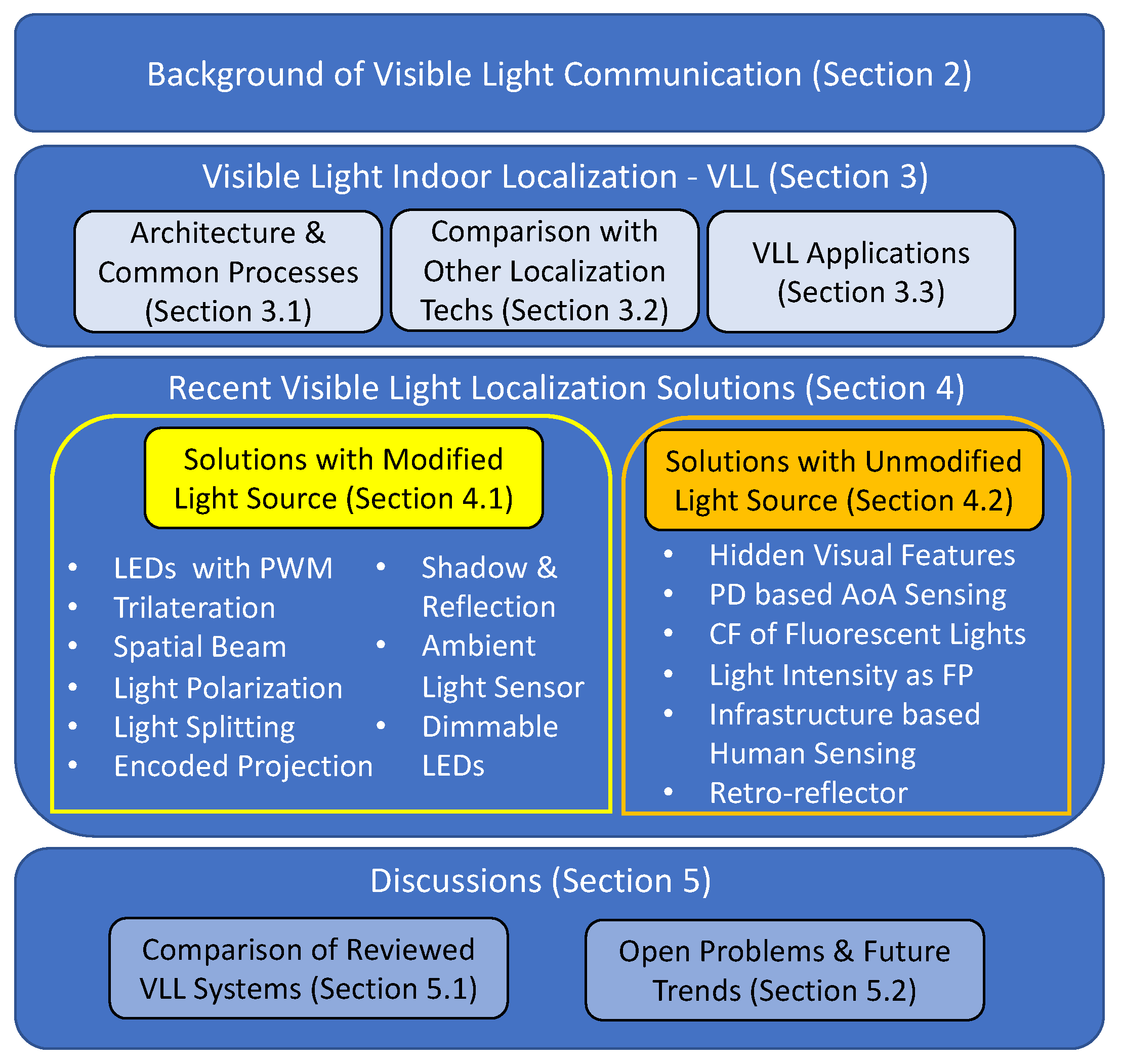
4. Recent Visible Light Localization Solutions
4.1. Solutions with Modified Light Source
4.1.1. LEDs with Pulse Width Modulation
4.1.2. Trilateration and Fusion of RSS and IMU
- Trilateration: Trilateration is mainly a process from geometry where a point is located on the basis of the intersecting shapes, mainly circles. In this case, it is the circular area of the strength received from a certain light source. If the distance from the sources can be calculated precisely, then the intersecting location can be measured from them. The more accurate the measurement of distance is, the more accurate the trilateration.The transmitted energy at the light source is a function of the duty cycle of the Pulse Width Modulation (PWM). The light source also needs to deliver the duty cycle information through the beacon for the receiver to correctly model the transmitted power. In Epsilon [43], the RSS measured at the receiver end is calculated as the following equation:where C is a constant related to the maximum emission power, and is the duty cycle of the LED. These two are included in the beacon. is the incidence angle, and is the irradiation angle. And finally, d is the actual sender–receiver distance. Epsilon uses Binary Frequency Shift Keying (BFSK) modulation scheme for its beaconing. For localization, it uses Equation (1) to estimate the distance and then computes the 3D coordinates of the receiver uniquely when the number of light sources is four or more.Note that trilateration has been widely used in localization systems (including VLL systems). Mousa et al. [61] also proposed a localization system using signal strength-based trilateration. It considers both scenarios of traditional Line of Sight (LoS) and Line of Sight with Non-line of Sight (LoSNLoS) and the effects of noise. For the LoSNLoS case, the effect of first order reflections is considered. Wu et al. [62] used various geometrical and optical formulae derived from trilateration equations to determine the X and Y coordinates. Each LED is modulated by CDMA format with unique ID information related to its geographical position. The Z coordinate is determined using a modified differential evolution (DE) algorithm. This work converts the whole positioning problem into an optimization problem and then tries to optimize it using the DE algorithm. Trilateration has also been used in [63] and [64], but more precisely, they are based on Phase Difference of Arrival (PDoA) or Time Difference of Arrival (TDoA).
- Involving the user: This is the case when there is an insufficient number of light sources, i.e., one or two. For solving this type of scenario, two steps are performed in Epsilon [43]. The first step is similar to finding direction using a compass. The user holds the phone horizontally and then rotates the phone along the Z-axis to point at the light source. The second step is to gradually pitch the phone, and in the meantime, the RSS values are also collected while the pitch is being changed. With these two steps, the inertial sensors of the phone are used to find out the irradiation and incidence angles, and the orientation angle is also measured. Finally, all of the measured values are put into a localizing function to find out the location.
4.1.3. Spatial Beams
- 2D Localization: The whole area of projected space is actually a polar form grid, as shown in Figure 5a. The receiver’s location in polar coordinates would be , where r is the radius, and is the angle. The shade rotates around the LED at a certain , and for the shade to rotate around a cell and again come back to it requires a certain time called the cell period. The controller not only controls the step motor to rotate the shade but also switches on and off the light at two pre-defined frequencies. There is an opto-isolator, which helps the receiver to find its angle. The opto-isolator is a U-shaped object, which transmits infrared (IR) from one side to another. However, there is a plastic barrier in-between so that it blocks the IR light once the cell period triggers a state change, and the controller changes its flash rate. In the meantime, the receiver counts the number of cells passed to estimate its angle. The shade has some hollow parts and some solid parts. The hollow part represents the 1 and the closed solid part represents the 0. So, whenever the shade rotates, the hollow and closed cell comes in turns, and it actually represents a set of bits. So, each ring has a fixed bit pattern in it. And the code contains three parts: (1) leading bits, which helps the receiver to understand the start point of the shade, (2) ring ID bits helps to identify rings and (3) extension bits. The received signals are processed for the cell recognition. The ring ID part gives the receiver’s ring number directly. And the time interval between the first flash rate switch point and the beginning of the leading bits represents the receiver’s cell number. The center of the determined cell is taken as the receiver’s location.
- 3D Localization: In the case of 3D localization, the received light beam pattern will be the same at different heights. If a line is drawn from the transmitter LED to the receiver, then there are an infinite number of positions or heights that satisfy the same received pattern. However, if there are multiple transmitters, then we can find the intersecting point by drawing lines from them too and find out the exact height of the receiver. In Figure 5b, there are two transmitters and , and the lines drawn from them are and , respectively, which intersect at R to give the height of the receiver.
4.1.4. Light Polarization
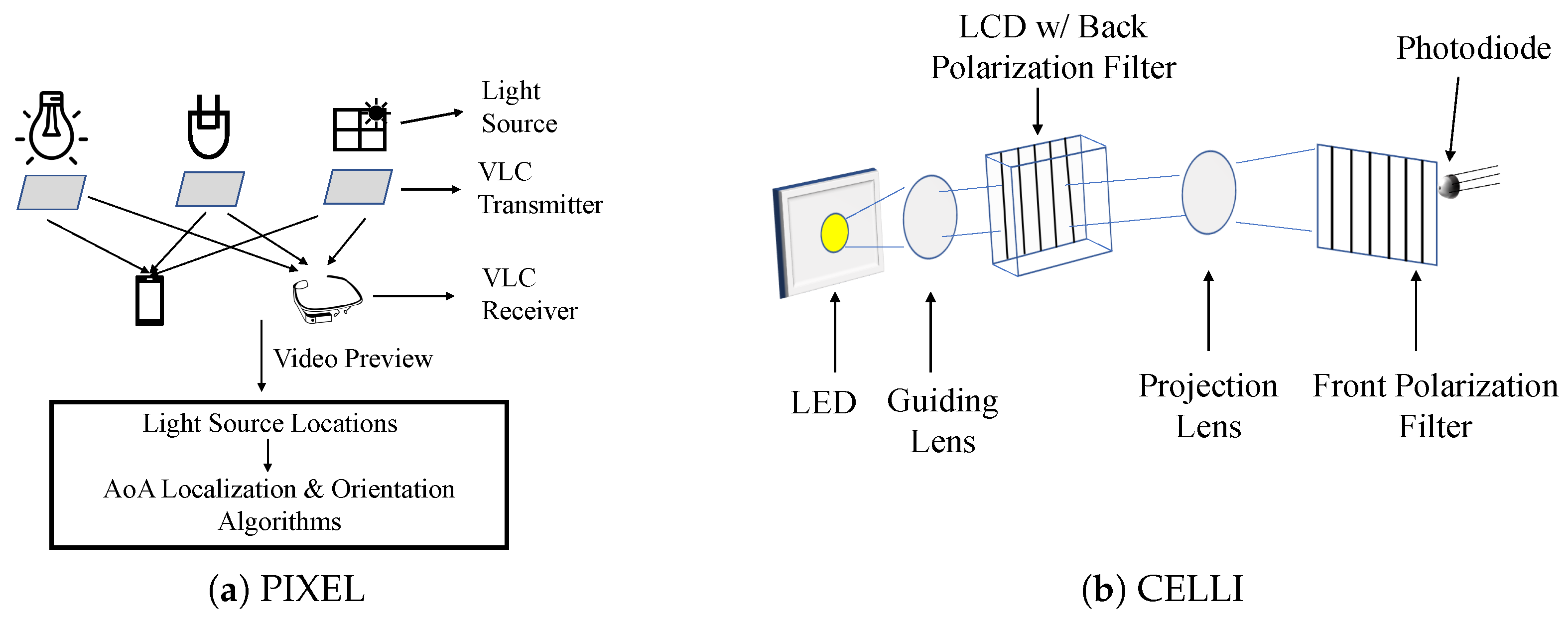
- Using Liquid Crystal: In most of the VLC systems, light flickering is an issue. Modulation is done on the intensity of light, and high rate pulses are needed to transmit. This rate goes beyond 1 kHz so that it is imperceptible to humans. However, for the receiving side, this is a burden. To address this problem, Yang et al. [44] proposed a system, PIXEL, which does modulation on the polarized light via liquid crystal. As shown in Figure 6a, there are mainly three parts of the system: the VLC transmitter, VLC receiver, and the AoA based localization and orientation algorithm. The light source can be any illuminating sources, including the sun light coming through a window. The VLC transmitter is attached to the surface of light sources for polarization. PIXEL is inspired by Liquid Crystal Display (LCD). In LCDs, there are two polarizer layers and one liquid crystal layer in the middle. In PIXEL, the transmitter contains a polarizer layer and dispersor and a liquid crystal in the middle, while the second polarizer layer is on the receiving side. The transmitter implements a modulation scheme known as the Binary Color Shift Keying (BCSK). As the receiving side is a smart phone or wearable device carried by users, there is mobility, which affects the effective intensity difference between the layers. For this reason, PIXEL uses the dispersor so that it splits the polarized light into different colors and causes a difference in the intensity. The receiving smart device captures the beacons using its camera’s video preview. From the video, the relative positions of the light sources can be found. To determine the beacon’s identity, the VLC receiver decodes it with a database that stores the identities corresponding to the light sources. An optimized version of the AoA-based localization and orientation algorithm [42] is applied. The optimization was done by applying the widely used Levenberg–Marquardt algorithm [66]. Inspired from PIXEL, another system called POLI [67] is introduced for visible-light-based communication. In POLI, the optical rotatory dispersor is used to separate the RGB channels and incorporate a point-to-point communication system.
- Interference-free (IF) Polarized Light Beams: CELLI by Wei et al. [68] has tweaked the transmitter. A small LCD is installed at the transmitter to project a large number of narrow and interference-free polarized light beams in the spatial domain. These polarized light beams are unique to each projected cell. The receiver then receives the unique transmission and identifies its located cell. As shown in Figure 6b, the guiding lens in front of the LED refracts the light towards the LCD. There is another projection lens to refract the polarized light rays from the LCD to project to the spatial cells. A filter detached from the LCD is attached in front of the receiver. The high spatial resolution of LCD is an advantage that helps CELLI to achieve higher fine-grained positioning. Though the CELLI receiver can calculate the coordinates, it cannot find the absolute location of the receiver. To find out the height’s information, a two-lens strategy at the transmitter side is introduced. Now the receiver receives two values of projection from the transmitter side. The geometrical properties could be leveraged to find the height and the absolute location of the receiver.
- Light Polarization Pattern with IMU Tracking: The authors of [69] used ubiquitous lights to correct the errors caused by Inertial Measurement Unit (IMU) tracking and increase the overall localization accuracy. IMU-based tracking methods are widely used but suffer from a famous problem known as the drifting problem. To solve it, many techniques (such as landmark-based and WiFi fingerprints) have been used to correct the drifting errors. The research in [69] cast passive and imperceptible light polarization patterns for the same purpose, and replies on existing indoor luminaries. It attaches a thin polarizer film to the light cover/diffuser to create the polarized light, as shown in Figure 7. This type of polarizer generally allows some kinds of polarized light and blocks. To create a spatial pattern, it makes use of the birefringence property. Transparent tape is used as an anisotropic material, which rotates the polarization of a light ray based on the refractive index using the birefringence property. For this, the white light will be divided into several color light beams in different directions. A colored sensor, covered with a polarizer, monitors its R/G/B channel input for color changes to detect the light pattern and the edge-crossing event.
4.1.5. Light Splitting Properties of Convex Lens
4.1.6. Encoded Projection
4.1.7. Shadow and Reflection
4.1.8. Ambient Light Sensor
4.1.9. Dimmable LEDs
4.2. Solutions with Unmodified Light Source
4.2.1. Hidden Visual Features of Lamps
4.2.2. PD-Based AoA Sensing
4.2.3. Characteristic Frequency of Fluorescent Lights
4.2.4. Light Intensity as Fingerprints
4.2.5. Infra-Structure-based Human Sensing
4.2.6. Retro-Reflector
5. Discussions
5.1. Comparison of the Reviewed VLL Systems
5.2. Open Problems and Future Trends
- Line of Sight (LoS) Problem. One of the major concerns with all the systems is the line of sight problem. Anything blocking the line of sight between the transmitter and the receiver is halting the whole system or significantly affecting the accuracy. In EyeLight [55], the LoS problem is addressed by leveraging shadows, but the accuracy is not as good as those with LoS. To find a way to solve the LoS problem with better accuracy is still a challenge.
- Co-existence and Interference. Another issue is the presence of multiple visible light-based systems in a scenario, which may cause interference to each other. To make a VLL system invulnerable to this type of issue might be another research direction.
- Integration with Other Sensing/Localization Techniques. Building new localization systems fusing multiple techniques along with visible light to gain more accuracy is also a promising path for future research. Note that [43,52] have used IMU sensing data to enhance their performances. Wang et al. [83] have exploited the bi-modal magnetic field and ambient light data obtained by smartphone magnetic and light sensors for indoor localization with a deep learning approach based on LSTM (long short-term memory).
- Advanced Machine Learning. Recently, advanced machine learning techniques (such as deep learning and reinforcement learning) have made significant impacts in many computer science areas, including smart sensing. However, machine learning techniques have not been widely applied in current VLL systems. There are a few exceptions, for example, KNN is used in [52,73,74], second order regression and polynomial trilateral ML model are used in [84], neural network is used in [76,78,85], and deep LSTM mode is used in [83]. We strongly believe that emerging advanced machine learning techniques can play more important roles in future VLL systems.
- Device Free. As most of the systems use devices as the receiver, building a device-free VLL system is still a future research direction. A VLL system without carrying any device (such as [55]) can be applied to a wider range of applications.
- Mobile Crowd Sensing. Recently, mobile crowd sensing (MCS) [86,87] has become an emerging sensing paradigm for many mobile sensing applications, including indoor localization [88,89,90,91]. The basic idea is leveraging a large number of mobile users carried with smart devices to collaboratively perform sensing, localization, or tracking tasks. Such an idea can also be used for VLL systems to perform light fingerprint collection or peer-to-peer calibration and may also potentially solve the LoS problem. Recently, in [39], Keskin et al. proposed a cooperative VLL system that leverages the communications among VLC receiver units to improve the accuracy of localization via cooperation. Such system shows the potential of cooperative VLL systems.
- Security. Security aspects of VLL systems are still an open research area. Some preliminary discussions have been provided by [92] for VLC, including possible Denial of Service attacks, which use a directional light source to disturb the sink node from receiving a packet via VLC. Note that such attacks can also hurt VLL systems based on VLC. A more thorough study on possible attacks and defenses for VLL systems is critical to wide applications of VLL.
- Robust Localization. Last but not least, how to achieve more robust localization is always a challenge. Keskin et al. [39] point out a possible way to achieve robust localization results in the case of mobile entities by using temporal cooperation. Temporal cooperation is to account for the previous steps’ information and use it for the current step. In [93], a two-phase framework is proposed to increase robustness when subject to insufficient anchor lights. The coarse phase produces a weighted proximity estimate with as few as one reference light source within a mobile terminal’s FoV, and then a fine phase performs conventional positioning algorithms if sufficient reference light sources are within the FoV. There is still room for innovation to build a robust system that is more feasible than the existing ones.
6. Conclusions
Author Contributions
Funding
Conflicts of Interest
References
- Schiller, J.; Voisard, A. Location-Based Services; Morgan Kaufmann: San Francisco, CA, USA, 2004. [Google Scholar]
- Bo, C.; Jung, T.; Mao, X.; Li, X.Y.; Wang, Y. SmartLoc: Sensing Landmarks Silently for Smartphone Based Metropolitan Localization. J. Wirel. Com. Netw. 2016, 111. [Google Scholar] [CrossRef] [Green Version]
- Chen, H.; Li, F.; Wang, Y. EchoTrack: Acoustic Device-free Hand Tracking on Smart Phones. In Proceedings of the IEEE 36th Conference on Computer Communications (INFOCOM 2017), Atlanta, GA, USA, 1–4 May 2017. [Google Scholar]
- Wang, Y.; Li, L. Localization in Wireless Sensor Networks. In RFID and Sensor Networks: Architectures, Protocols, Security and Integrations; Zhang, Y., Yang, L.T., Chen, J., Eds.; Auerbach Publications; Taylor & Francis Group: Boca Raton, FL, USA, 2009. [Google Scholar]
- Yang, C.; Shao, H.R. WiFi-based indoor positioning. IEEE Commun. Mag. 2015, 53, 150–157. [Google Scholar] [CrossRef]
- Biswas, J.; Veloso, M. WiFi localization and navigation for autonomous indoor mobile robots. In Proceedings of the 2010 IEEE International Conference on Robotics and Automation, Anchorage, AK, USA, 3–7 May 2010; pp. 4379–4384. [Google Scholar] [CrossRef] [Green Version]
- Liu, H.; Yang, J.; Sidhom, S.; Wang, Y.; Chen, Y.; Ye, F. Accurate WiFi Based Localization for Smartphones Using Peer Assistance. IEEE Trans. Mob. Comput. 2014, 13, 2199–2214. [Google Scholar] [CrossRef]
- Chang, L.; Xiong, J.; Wang, Y.; Chen, X.; Hu, J.; Fang, D. iUpdater: Low Cost Fingerprint Matrix Updates for Device-free Localization. In Proceedings of the 37th IEEE International Conference on Distributed Computing (ICDCS 2017), Atlanta, GA, USA, 5–8 June 2017. [Google Scholar]
- Chang, L.; Chen, X.; Wang, Y.; Fang, D.; Wang, J.; Xing, T.; Tang, Z. FitLoc: Fine-grained and Low-cost Device-free Localization for Multiple Targets over Various Areas. In Proceedings of the 35th Annual IEEE International Conference on Computer Communications (IEEE INFOCOM 2016), San Francisco, CA, USA, 10–14 April 2016. [Google Scholar]
- Chang, L.; Chen, X.; Wang, Y.; Fang, D.; Wang, J.; Xing, T.; Tang, Z. FitLoc: Fine-grained and Low-cost Device-free Localization for Multiple Targets over Various Areas. IEEE/ACM Trans. Netw. 2017, 25, 1994–2007. [Google Scholar] [CrossRef]
- Ni, L.M.; Liu, Y.; Lau, Y.C.; Patil, A.P. LANDMARC: Indoor location sensing using active RFID. In Proceedings of the First IEEE International Conference on Pervasive Computing and Communications, Fort Worth, TX, USA, 26–26 March 2003; pp. 407–415. [Google Scholar] [CrossRef]
- Zhao, Y.; Liu, Y.; Ni, L.M. VIRE: Active RFID-based Localization Using Virtual Reference Elimination. In Proceedings of the 2007 International Conference on Parallel Processing (ICPP 2007), Xi’an, China, 10–14 September 2007. [Google Scholar]
- Yang, P.; Wu, W. Efficient Particle Filter Localization Algorithm in Dense Passive RFID Tag Environment. IEEE Trans. Ind. Electron. 2014, 61, 5641–5651. [Google Scholar] [CrossRef]
- Bahl, P.; Padmanabhan, V.N. RADAR: An in-building RF-based user location and tracking system. In Proceedings of the IEEE INFOCOM 2000, Tel Aviv, Israel, 26–30 March 2000. [Google Scholar]
- Hossain, A.K.M.M.; Soh, W.S. A Comprehensive Study of Bluetooth Signal Parameters for Localization. In Proceedings of the 2007 IEEE 18th International Symposium on Personal, Indoor and Mobile Radio Communications, Athens, Greece, 3–7 September 2007. [Google Scholar] [CrossRef]
- Zhuang, Y.; Yang, J.; Li, Y.; Qi, L.; El-Sheimy, N. Smartphone-Based Indoor Localization with Bluetooth Low Energy Beacons. Sensors 2016, 16, 596. [Google Scholar] [CrossRef] [Green Version]
- Wang, Y.; Ye, Q.; Cheng, J.; Wang, L. RSSI-Based Bluetooth Indoor Localization. In Proceedings of the 2015 11th International Conference on Mobile Ad-hoc and Sensor Networks (MSN), Shenzhen, China, 16–18 December 2015. [Google Scholar] [CrossRef]
- Ridolfi, M.; Van de Velde, S.; Steendam, H.; De Poorter, E. Analysis of the Scalability of UWB Indoor Localization Solutions for High User Densities. Sensors 2018, 18, 1875. [Google Scholar] [CrossRef] [Green Version]
- Tiemann, J.; Wietfeld, C. Scalable and Precise Multi-UAV Indoor Navigation using TDOA-based UWB Localization. In Proceedings of the 2017 International Conference on Indoor Positioning and Indoor Navigation (IPIN), Sapporo, Japan, 18–21 September 2017. [Google Scholar] [CrossRef]
- Huang, W.; Xiong, Y.; Li, X.Y.; Lin, H.; Mao, X.; Yang, P.; Liu, Y. Shake and walk: Acoustic direction finding and fine-grained indoor localization using smartphones. In Proceedings of the IEEE INFOCOM 2014-IEEE Conference on Computer Communications, Toronto, ON, Canada, 27 April–2 May 2014. [Google Scholar]
- Tarzia, S.P.; Dinda, P.A.; Dick, R.P.; Memik, G. Indoor localization without infrastructure using the acoustic background spectrum. In Proceedings of the 9th international conference on Mobile systems, applications, and service, Bethesda, MD, USA, 28 June–1 July 2011. [Google Scholar]
- Chen, H.; Li, F.; Wang, Y. SoundMark: Accurate Indoor Localization via Peer-Assisted Dead Reckoning. IEEE IoT J. 2018, 5, 4803–4815. [Google Scholar] [CrossRef]
- Yi, J.; Zhang, J.; Song, D.; Jayasuriya, S. IMU-based localization and slip estimation for skid-steered mobile robots. In Proceedings of the 2007 IEEE/RSJ International Conference on Intelligent Robots and Systems, San Diego, CA, USA, 29 October–2 November 2007. [Google Scholar] [CrossRef]
- Zhang, R.; Hoflinger, F.; Reindl, L. Inertial Sensor Based Indoor Localization and Monitoring System for Emergency Responders. IEEE Sens. J. 2013, 13, 838–848. [Google Scholar] [CrossRef]
- Ruiz, A.R.J.; Granja, F.S.; Honorato, J.C.P.; Rosas, J.I.G. Accurate Pedestrian Indoor Navigation by Tightly Coupling Foot-Mounted IMU and RFID Measurements. IEEE Trans. Instrum. Meas. 2012, 61, 178–189. [Google Scholar] [CrossRef] [Green Version]
- Pathak, P.H.; Feng, X.; Hu, P.; Mohapatra, P. Visible Light Communication, Networking, and Sensing: A Survey, Potential and Challenges. IEEE Commun. Surv. Tutor. 2015, 17, 2047–2077. [Google Scholar] [CrossRef]
- Tsonev, D.; Chun, H.; Rajbhandari, S.; McKendry, J.J.D.; Videv, S.; Gu, E.; Haji, M.; Watson, S.; Kelly, A.E.; Faulkner, G.; et al. A 3-Gb/s Single-LED OFDM-Based Wireless VLC Link Using a Gallium NitrideμLED. IEEE Photonics Technol. Lett. 2014, 26, 637–640. [Google Scholar] [CrossRef]
- Sevincer, A.; Bhattarai, A.; Bilgi, M.; Yuksel, M.; Pala, N. LIGHTNETs: Smart LIGHTing and Mobile Optical Wireless NETworks—A Survey. IEEE Commun. Surv. Tutor. 2013, 15, 1620–1641. [Google Scholar] [CrossRef]
- Mukherjee, M. Visible light communication-A survey of potential research challenges and advancements. In Proceedings of the 2017 Second International Conference on Electrical, Computer and Communication Technologies (ICECCT), Coimbatore, India, 22–24 February 2017; pp. 1–8. [Google Scholar] [CrossRef]
- Noshad, M.; Brandt-Pearce, M. Can Visible Light Communications Provide Gb/s Service? arXiv 2013, arXiv:1308.3217. [Google Scholar]
- Karunatilaka, D.; Zafar, F.; Kalavally, V.; Parthiban, R. LED Based Indoor Visible Light Communications: State of the Art. IEEE Commun. Surv. Tutor. 2015, 17, 1649–1678. [Google Scholar] [CrossRef]
- Plets, D.; Bastiaens, S.; Martens, L.; Joseph, W. An Analysis of the Impact of LED Tilt on Visible Light Positioning Accuracy. Electronics 2019, 8, 389. [Google Scholar] [CrossRef] [Green Version]
- Yuan, T.; Xu, Y.; Wang, Y.; Han, P.; Chen, J. A Tilt Receiver Correction Method for Visible Light Positioning Using Machine Learning Method. IEEE Photonics J. 2018, 10, 1–12. [Google Scholar] [CrossRef]
- Ghassemlooy, Z. Indoor Optical Wireless Communication Systems—Part I: Review; Technical Report; Northumbria University: Newcastle upon Tyne, UK, 2003; Available online: http://soe.northumbria.ac.uk/ocr/downloads/partI-rev.pdf (accessed on 3 March 2020).
- Tsai, C.C.; Chen, M.H.; Huang, Y.C.; Hsu, Y.C.; Lo, Y.T.; Lin, Y.J.; Kuang, J.H.; Huang, S.B.; Hu, H.L.; Su, Y.I.; et al. Decay Mechanisms of Radiation Pattern and Optical Spectrum of High-Power LED Modules in Aging Test. IEEE J. Sel. Top. Quantum Electron. 2009, 15, 1156–1162. [Google Scholar] [CrossRef]
- Rehman, S.; Ullah, S.; Chong, P.; Yongchareon, S.; Komosny, D. Visible Light Communication: A System Perspective—Overview and Challenges. Sensors 2019, 19, 1153. [Google Scholar] [CrossRef] [Green Version]
- Khan, L.U. Visible light communication: Applications, architecture, standardization and research challenges. Digit. Commun. Netw. 2017, 3, 78–88. [Google Scholar] [CrossRef] [Green Version]
- Hassan, N.U.; Naeem, A.; Pasha, M.A.; Jadoon, T.; Yuen, C. Indoor Positioning Using Visible LED Lights: A Survey. ACM Comput. Surv. 2015, 48. [Google Scholar] [CrossRef]
- Keskin, M.F.; Sezer, A.D.; Gezici, S. Localization via Visible Light Systems. Proc. IEEE 2018, 106, 1063–1088. [Google Scholar] [CrossRef]
- Zhuang, Y.; Hua, L.; Qi, L.; Yang, J.; Cao, P.; Cao, Y.; Wu, Y.; Thompson, J.; Haas, H. A Survey of Positioning Systems Using Visible LED Lights. IEEE Commun. Surv. Tutor. 2018, 20, 1963–1988. [Google Scholar] [CrossRef] [Green Version]
- Jensfelt, P.; Christensen, H.I. Laser Based Position Acquisition and Tracking in an Indoor Environment. In Proceedings of the International Symposium on Robotics and Automation, Saltillo, Mexico, 12–14 December 1998; pp. 331–338. [Google Scholar]
- Kuo, Y.S.; Pannuto, P.; Hsiao, K.J.; Dutta, P. Luxapose: Indoor Positioning with Mobile Phones and Visible Light. In Proceedings of the 20th Annual International Conference on Mobile Computing and Networking, Maui, HI, USA, 7–11 September 2014. [Google Scholar] [CrossRef] [Green Version]
- Li, L.; Hu, P.; Peng, C.; Shen, G.; Zhao, F. Epsilon: A Visible Light Based Positioning System. In Proceedings of the 11th USENIX Conference on Networked Systems Design and Implementation, Seattle, WA, USA, 2–4 April 2014. [Google Scholar]
- Yang, Z.; Wang, Z.; Zhang, J.; Huang, C.; Zhang, Q. Wearables Can Afford: Light-weight Indoor Positioning with Visible Light. In Proceedings of the 13th Annual International Conference on Mobile Systems, Applications, and Services, Florence, Italy, 19–22 May 2015. [Google Scholar]
- Liu, S.; He, T. SmartLight: Light-weight 3D Indoor Localization Using a Single LED Lamp. In Proceedings of the 15th ACM Conference on Embedded Network Sensor Systems, Delft, The Netherlands, 6–8 November 2017. [Google Scholar]
- Ma, S.; Liu, Q.; Sheu, P.C. Foglight: Visible Light-Enabled Indoor Localization System for Low-Power IoT Devices. IEEE IoT J. 2018, 5, 175–185. [Google Scholar] [CrossRef]
- Wang, Z.; Yang, Z.; Huang, Q.; Yang, L.; Zhang, Q. ALS-P: Light Weight Visible Light Positioning via Ambient Light Sensor. In Proceedings of the IEEE Conference on Computer Communications, Paris, France, 29 April–2 May 2019. [Google Scholar] [CrossRef]
- Liu, X.; Wei, X.; Guo, L. DIMLOC: Enabling High-Precision Visible Light Localization Under Dimmable LEDs in Smart Buildings. IEEE IoT J. 2019, 6, 3912–3924. [Google Scholar] [CrossRef]
- Zhu, S.; Zhang, X. Enabling High-Precision Visible Light Localization in Today’s Buildings. In Proceedings of the 15th Annual International Conference on Mobile Systems, Applications, and Services, Niagara Falls, NY, USA, 19–23 June 2017. [Google Scholar] [CrossRef]
- Zhang, C.; Zhang, X. Pulsar: Towards Ubiquitous Visible Light Localization. In Proceedings of the 23rd Annual International Conference on Mobile Computing and Networking, Snowbird, UT, USA, 16–20 October 2017. [Google Scholar] [CrossRef]
- Zhang, C.; Zhang, X. LiTell: Robust Indoor Localization Using Unmodified Light Fixtures. In Proceedings of the 22nd Annual International Conference on Mobile Computing and Networking, New York, NY, USA, 3–7 October 2016. [Google Scholar] [CrossRef]
- Zhao, Z.; Wang, J.; Zhao, X.; Peng, C.; Guo, Q.; Wu, B. NaviLight: Indoor localization and navigation under arbitrary lights. In Proceedings of the IEEE Conference on Computer Communications, Atlanta, GA, USA, 1–4 May 2017. [Google Scholar] [CrossRef]
- Li, T.; Liu, Q.; Zhou, X. Practical Human Sensing in the Light. In Proceedings of the 14th Annual International Conference on Mobile Systems, Applications, and Services, Singapore, 26–30 June 2016. [Google Scholar] [CrossRef] [Green Version]
- Wang, Q.; Zuniga, M.; Giustiniano, D. Passive Communication with Ambient Light. In Proceedings of the 12th International on Conference on Emerging Networking EXperiments and Technologies, Irvine, CA, USA, 12–15 December 2016. [Google Scholar] [CrossRef] [Green Version]
- Nguyen, V.; Ibrahim, M.; Rupavatharam, S.; Jawahar, M.; Gruteser, M.; Howard, R. Eyelight: Light-and-Shadow-Based Occupancy Estimation and Room Activity Recognition. In Proceedings of the IEEE INFOCOM 2018-IEEE Conference on Computer Communications, Honolulu, HI, USA, 16–19 April 2018. [Google Scholar] [CrossRef]
- Shao, S.; Khreishah, A.; Khalil, I. RETRO: Retroreflector Based Visible Light Indoor Localization for Real-time Tracking of IoT Devices. In Proceedings of the IEEE INFOCOM 2018-IEEE Conference on Computer Communications, Honolulu, HI, USA, 16–19 April 2018. [Google Scholar] [CrossRef]
- Mainetti, L.; Patrono, L.; Sergi, I. A survey on indoor positioning systems. In Proceedings of the 2014 22nd International Conference on Software, Telecommunications and Computer Networks (SoftCOM), Split, Croatia, 17–19 September 2014. [Google Scholar] [CrossRef]
- Zafari, F.; Gkelias, A.; Leung, K.K. A Survey of Indoor Localization Systems and Technologies. IEEE Commun. Surv. Tutor. 2019, 21, 2568–2599. [Google Scholar] [CrossRef] [Green Version]
- Youssef, M.; Mah, M.; Agrawala, A. Challenges: Device-free Passive Localization for Wireless Environments. In Proceedings of the 13th Annual ACM International Conference on Mobile Computing and Networking, Montréal, QC, Canada, 9–14 September 2007. [Google Scholar] [CrossRef]
- Peng, Q.; Guan, W.; Wu, Y.; Cai, Y.; Xie, C.; Wang, P. Three-dimensional high-precision indoor positioning strategy using Tabu search based on visible light communication. Opt. Eng. 2018, 57, 1–11. [Google Scholar] [CrossRef]
- Mousa, F.I.K.; Almaadeed, N.; Busawon, K.; Bouridane, A.; Binns, R.; Elliott, I. Indoor visible light communication localization system utilizing received signal strength indication technique and trilateration method. Opt. Eng. 2018, 57, 1–10. [Google Scholar] [CrossRef]
- Wu, Y.; Liu, X.; Guan, W.; Chen, B.; Chen, X.; Xie, C. High-speed 3D indoor localization system based on visible light communication using differential evolution algorithm. Opt. Commun. 2018, 424, 177–189. [Google Scholar] [CrossRef]
- Naz, A.; Asif, H.M.; Umer, T.; Kim, B. PDOA Based Indoor Positioning Using Visible Light Communication. IEEE Access 2018, 6, 7557–7564. [Google Scholar] [CrossRef]
- Du, P.; Zhang, S.; Chen, C.; Alphones, A.; Zhong, W. Demonstration of a Low-Complexity Indoor Visible Light Positioning System Using an Enhanced TDOA Scheme. IEEE Photonics J. 2018, 10, 1–10. [Google Scholar] [CrossRef]
- Xie, B.; Tan, G.; He, T. SpinLight: A High Accuracy and Robust Light Positioning System for Indoor Applications. In Proceedings of the 13th ACM Conference on Embedded Networked Sensor Systems, Seoul, Korea, 1–4 November 2015. [Google Scholar] [CrossRef]
- Marquardt, D.W. An Algorithm for Least Square Estimation of Non-Linear Parameters. SIAM J. Appl. Math. 1963, 11, 431–441. [Google Scholar] [CrossRef]
- Chan, C.L.; Tsai, H.M.; Lin, K.C.J. POLI: Long-Range Visible Light Communications Using Polarized Light Intensity Modulation. In Proceedings of the ACM MobiSys 2017, Niagara Falls, NY, USA, 19–23 June 2017. [Google Scholar] [CrossRef]
- Wei, Y.L.; Huang, C.J.; Tsai, H.M.; Lin, K.C.J. CELLI: Indoor Positioning Using Polarized Sweeping Light Beams. In Proceedings of the 15th Annual International Conference on Mobile Systems, Applications, and Services, Niagara Falls, NY, USA, 19–23 June 2017. [Google Scholar] [CrossRef]
- Tian, Z.; Wei, Y.L.; Xiong, X.; Chang, W.N.; Tsai, H.M.; Lin, K.C.J.; Zheng, C.; Zhou, X. Position: Augmenting Inertial Tracking with Light. In Proceedings of the 4th ACM Workshop on Visible Light Communication Systems, Snowbird, UT, USA, 16 October 2017. [Google Scholar] [CrossRef]
- Yang, F.; Li, S.; Zhang, J.; Xu, S.; Cong, L.; An, Y. STARLIT: 3D indoor positioning with smartphones and reflection light. In Proceedings of the ACM Turing Celebration Conference, Chengdu, China, 17–19 May 2019. [Google Scholar] [CrossRef]
- Chase, R. The Initiation and Conduction of Action Potentials in the Optic Nerve of Tritonia. J. Exp. Biol. 1974, 60, 721–734. [Google Scholar] [PubMed]
- Zhang, C.; Zhang, X. Visible Light Localization Using Conventional Light Fixtures and Smartphones. IEEE Trans. Mob. Comput. 2018, 18, 2968–2983. [Google Scholar] [CrossRef]
- Wenge, T.; Chew, M.T.; Alam, F.; Gupta, G.S. Implementation of a visible light based indoor localization system. In Proceedings of the 2018 IEEE Sensors Applications Symposium (SAS), Seoul, Korea, 12–14 March 2018; pp. 1–6. [Google Scholar] [CrossRef]
- Munir, B.; Dyo, V. Passive Localization through Light Flicker Fingerprinting. IEEE Sens. J. 2019. [Google Scholar] [CrossRef] [Green Version]
- Guo, X.; Shao, S.; Ansari, N.; Khreishah, A. Indoor Localization Using Visible Light Via Fusion of Multiple Classifiers. IEEE Photonics J. 2017, 9, 1–16. [Google Scholar] [CrossRef]
- Alonso-González, I.; Sánchez-Rodríguez, D.; Ley-Bosch, C.; Quintana-Suárez, M.A. Discrete Indoor Three-Dimensional Localization System Based on Neural Networks Using Visible Light Communication. Sensors 2018, 18, 1040. [Google Scholar] [CrossRef] [Green Version]
- Tran, H.Q.; Ha, C. Improved Visible Light-Based Indoor Positioning System Using Machine Learning Classification and Regression. Appl. Sci. 2019, 9, 1048. [Google Scholar] [CrossRef] [Green Version]
- Zhang, H.; Cui, J.; Feng, L.; Yang, A.; Lv, H.; Lin, B.; Huang, H. High-Precision Indoor Visible Light Positioning Using Modified Momentum Back Propagation Neural Network with Sparse Training Point. Sensors 2019, 19, 2324. [Google Scholar] [CrossRef] [Green Version]
- Zhang, R.; Zhong, W.; Qian, K.; Zhang, S.; Du, P. A Reversed Visible Light Multitarget Localization System via Sparse Matrix Reconstruction. IEEE IoT J. 2018, 5, 4223–4230. [Google Scholar] [CrossRef]
- Qin, L.; Niu, B.; Li, B.; Du, Y. Indoor Visible Light High Precision Three-Dimensional Positioning Algorithm Based on Single LED Lamp. Optik 2019, 163786. [Google Scholar] [CrossRef]
- Shao, S.; Khreishah, A.; Paez, J. PassiveRETRO: Enabling Completely Passive Visible Light Localization for IoT Applications. In Proceedings of the IEEE INFOCOM 2019—IEEE Conference on Computer Communications, Paris, France, 29 April–2 May 2019; pp. 1540–1548. [Google Scholar] [CrossRef]
- Plets, D.; Bastiaens, S.; Ijaz, M.; Almadani, Y.; Martens, L.; Raes, W.; Stevens, N.; Joseph, W. Three-dimensional Visible Light Positioning: an Experimental Assessment of the Importance of the LEDs’ Locations. In Proceedings of the 2019 International Conference on Indoor Positioning and Indoor Navigation (IPIN), Pisa, Italy, 30 September–3 October 2019. [Google Scholar] [CrossRef]
- Wang, X.; Yu, Z.; Mao, S. DeepML: Deep LSTM for Indoor Localization with Smartphone Magnetic and Light Sensors. In Proceedings of the 2018 IEEE International Conference on Communications (ICC), Kansas City, MO, USA, 20–24 May 2018. [Google Scholar] [CrossRef]
- Chuang, Y.C.; Li, Z.Q.; Hsu, C.W.; Liu, Y.; Chow, C.W. Visible light communication and positioning using positioning cells and machine learning algorithms. Opt. Express 2019, 27, 16377–16383. [Google Scholar] [CrossRef] [PubMed]
- Li, X.; Cao, Y.; Chen, C. Machine Learning Based High Accuracy Indoor Visible Light Location Algorithm. In Proceedings of the 2018 IEEE International Conference on Smart Internet of Things (SmartIoT), Xi’an, China, 17–19 August 2018; pp. 198–203. [Google Scholar] [CrossRef]
- Guo, B.; Wang, Z.; Yu, Z.; Wang, Y.; Yen, N.; Huang, R.; Zhou, X. Mobile Crowd Sensing and Computing: The Review of an Emerging Human-Powered Sensing Paradigm. ACM Comput. Surv. 2015, 48. [Google Scholar] [CrossRef]
- Li, H.; Li, T.; Wang, W.; Wang, Y. Dynamic Participant Selection for Large-Scale Mobile Crowd Sensing. IEEE Trans. Mob. Comput. 2019, 18, 2842–2855. [Google Scholar] [CrossRef]
- Guo, Y.; Li, Y.; Sun, Y. Accurate Indoor Localization Based on Crowd Sensing. In Proceedings of the 2016 International Wireless Communications and Mobile Computing Conference (IWCMC), Paphos, Cyprus, 5–9 September 2016; pp. 708–713. [Google Scholar]
- Zhou, X.; Chen, T.; Guo, D.; Teng, X.; Yuan, B. From One to Crowd: A Survey on Crowdsourcing-based Wireless Indoor Localization. Front. Comput. Sci. 2018, 12, 423–450. [Google Scholar] [CrossRef]
- Niu, J.; Wang, B.; Cheng, L.; Rodrigues, J.J.P.C. WicLoc: An Indoor Localization System Based on WiFi Fingerprints and Crowdsourcing. In Proceedings of the 2015 IEEE International Conference on Communications (ICC), London, UK, 8–12 June 2015. [Google Scholar]
- Chen, H.; Li, F.; Hei, X.; Wang, Y. CrowdX: Enhancing Automatic Construction of Indoor Floorplan with Opportunistic Encounters. IMWUT 2018, 2, 1–21. [Google Scholar] [CrossRef]
- Rohner, C.; Raza, S.; Puccinelli, D.; Voigt, T. Security in Visible Light Communication: Novel Challenges and Opportunities. Sens. Transducers J. 2015, 192, 9–15. [Google Scholar]
- Prince, G.B.; Little, T.D.C. Two-Phase Framework for Indoor Positioning Systems Using Visible Light. Sensors 2018, 18, 1917. [Google Scholar] [CrossRef] [Green Version]


| Challenge | References |
|---|---|
| Narrow bandwidth modulation of the light source, requiring further development of new modulation and coding techniques | [29,30] |
| Effects such as shadowing, path-loss, multipath propagation, and background noise effects | [29,31] |
| Interference with other VLC devices and the ambient light sources | [26,30,31] |
| Tilt position of the transmitter might cause changes of the transmitted signal | [31,32] |
| Tilt position of the receiver might cause changes of the received signal | [33] |
| Multiple access techniques and user mobility issues | [29,30] |
| Eye safety standards vs. limited transmission distance | [29,34] |
| Not working in light off mode | [29,31] |
| Deviations on the LED power due to aging, or tolerances on the power | [35] |
| Upgrading cost from current infrastructures | [29,36] |
| Integration with WiFi, Bluetooth, RFID, IMU, and other technologies | [37] |
| Wireless Technique | Transmission Range | Omni- Directional | Interference with | Passes through Opaque Wall | Power Consumption | Range of Accuracy |
|---|---|---|---|---|---|---|
| RFID | Long | Yes | RF Signal | Yes | Low | level |
| Acoustic | Short | Yes | Acoustic | Yes | Medium | level |
| Bluetooth | Short | Yes | RF Signal | Yes | Low | level |
| WiFi | Long | Yes | RF Signal | Yes | Medium | level |
| UWB | Short | Yes | Immune to Interference | Yes | Medium | level |
| Visible Light | Long | No | Light | No | Low | level |
| VLL Systems | Error (cm)/Percentile | Modified Light Source | Use of Smart Phones | Use of Photo Sensors | Device Free | 2D/3D Positioning | Experiment Configurations (Number of LEDs or FLs/Deployed Area (m2)) | Method Used |
|---|---|---|---|---|---|---|---|---|
| Luxapose [42] | 10/90% | Yes | Yes | No | No | Both | 5 LEDs/ | Phones and Modified LED Luminaries |
| Epsilon [43] | 40/90% | No | Yes | No | No | 3D | 5 LEDs/ or or | Trilateration and fusion of RSS and IMU |
| Spinlight [65] | 4/90% | Yes | No | Yes | No | Both | 1 LED/circular with radius 5.5 m | Spatial Beams |
| PIXEL [44] | 30/90% | Yes | Yes | No | No | 3D | 8 LEDs/ | Polarization and Liquid Crystal |
| CELLI-2D [68] | Median 1.07 | Yes | No | Yes | No | 2D | 1 LED with LCD/height 1.75 m | IF Polarized Light Beams |
| CELLI-3D [68] | Median 2.65 | Yes | No | Yes | No | 3D | 1 LED with LCD/height 2.25 m | IF Polarized Light Beams |
| PolarPattern [69] | NA | Yes | No | Yes | No | 3D | NA | Light Polarization Pattern |
| SmartLight [45] | 50/90% | Yes | No | Yes | No | 3D | LEDs array/ or | Light Splitting Prop. of Convex Lens |
| FogLight [46] | 0.3/90% | Yes | No | Yes | No | 2D | DLP Projector/ | Encoded Projections |
| EyeLight [55] | 250/90% | Yes | No | Yes | Yes | 2D | 7 LEDs/ | Shadow |
| STARLIT [70] | 55/80% | Yes | Yes | No | No | 3D | 1 LED/72 m2 | Reflection Light |
| ALS-P [47] | 25/90% | Yes | Yes | No | No | 3D | 4 LEDs/ | Ambient Light Sensor |
| DIMLOC [48] | 9/100% | Yes | Yes | No | No | 2D | 9 LEDs/ | Dimmable LEDs |
| iLAMP [49] | 3.5/90% | No | Yes | No | No | 3D | 588 FLs or 190 LEDs+129 FLs or 330 FLs/2.5 m or 3 m or 6 m ceiling | Hidden Visual Features of Lamps |
| Pulsar-2D [50] | 6/90% | No | Yes | Yes | No | 2D | 64 FLs or 110 CFLs or 157 FLs/3 m or 4 m or 2.8 m ceiling | PD based AoA Sensing |
| Pulsar-3D [50] | 31/90% | No | Yes | Yes | No | 3D | 64 FLs or 110 CFLs or 157 FLs/3 m or 4 m or 2.8 m ceiling | PD based AoA Sensing |
| LiTell [51] | 10–25/90% | No | Yes | No | No | 2D | 162 FLs/1000 | CF of Fluorescent Lights |
| NaviLight [52] | 35/85% | No | Yes | No | No | 2D | 130 or 38 or 30 LEDs/625 or 148 or 260 | Light Intensity as Fingerprint |
| Starlight [53] | 9/90% | No | No | Yes | No | 3D | 20 LED Panels/ | Infrastructure based Sensing |
| RETRO [56] | 2/90% | No | No | Yes | No | Both | 1 LED Panel/height 1.5 m | Retro-reflector |
| Assessment [82] | 21.1–277.8/95% | Yes | No | Yes | No | Both | 4 LEDs (Star or Square)/4 × 4 | RSS based Trilateration |
© 2020 by the authors. Licensee MDPI, Basel, Switzerland. This article is an open access article distributed under the terms and conditions of the Creative Commons Attribution (CC BY) license (http://creativecommons.org/licenses/by/4.0/).
Share and Cite
Rahman, A.B.M.M.; Li, T.; Wang, Y. Recent Advances in Indoor Localization via Visible Lights: A Survey. Sensors 2020, 20, 1382. https://doi.org/10.3390/s20051382
Rahman ABMM, Li T, Wang Y. Recent Advances in Indoor Localization via Visible Lights: A Survey. Sensors. 2020; 20(5):1382. https://doi.org/10.3390/s20051382
Chicago/Turabian StyleRahman, A B M Mohaimenur, Ting Li, and Yu Wang. 2020. "Recent Advances in Indoor Localization via Visible Lights: A Survey" Sensors 20, no. 5: 1382. https://doi.org/10.3390/s20051382