Complex Field Network Coding for Multi-Source Multi-Relay Single-Destination UAV Cooperative Surveillance Networks

Abstract
:1. Introduction
2. Design of the Topology Structure
3. Network Coding
3.1. The Classification of Network Coding
3.2. Information Transmission Based on Complex Field Network Coding (CFNC) in Mixed Mode
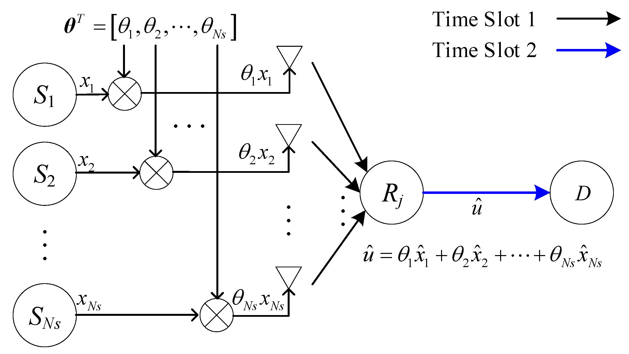
3.3. Information Transmission Based on CFNC in Relay Mode
4. Simulation Results and Analysis
4.1. Topology Structure Performance Evaluation
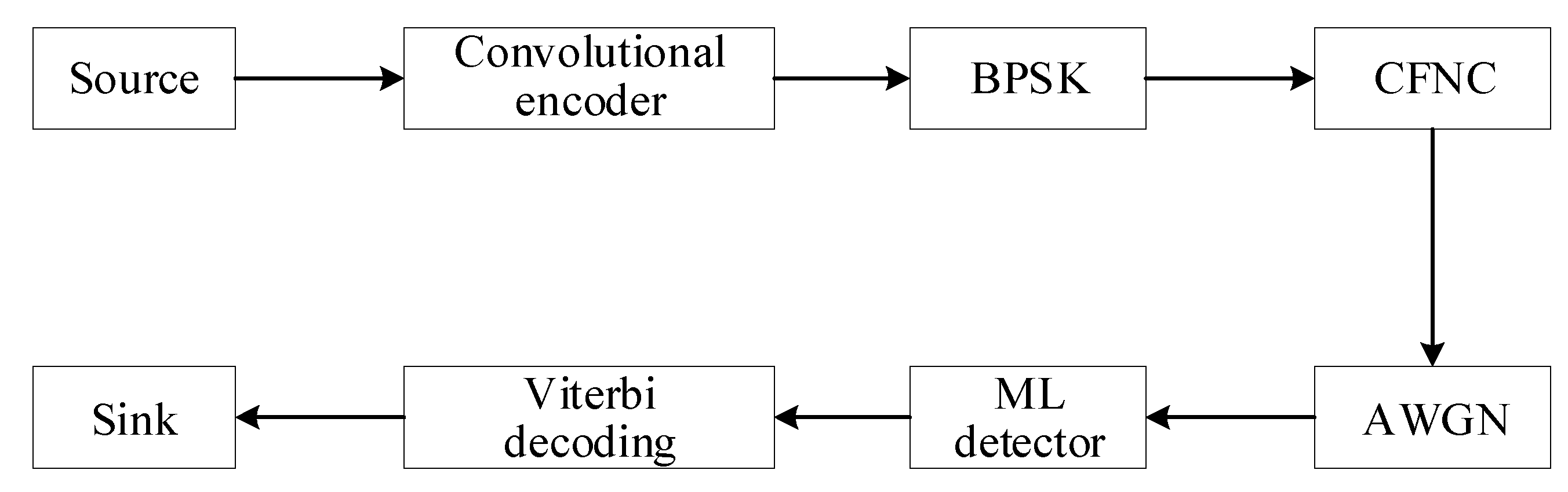
4.2. The Combination of CFNC and Conventional Unmanned Aerial Vehicle (UAV) Datalink
5. Conclusions
Author Contributions
Funding
Conflicts of Interest
Abbreviations
| UAV | Unmanned Aerial Vehicle |
| NC | Network Coding |
| GFNC | Galois Field Network Coding |
| RLNC | Random Linear Network Coding |
| PNC | Physical-layer Network Coding |
| CFNC | Complex Field Network Coding |
| AWGN | Additive White Gaussian Noise |
| MSMRSD | Multi-source multi-relay single-destination |
| LDPC | Low-density Parity-check |
| LCF | Linear Complex Field |
| TWRC | Two-way Relay Channel |
| TDMA | Time Division Multiple Access |
| CU | Channel Use |
| MIMO | Multiple Input Multiple Output |
| ML | Maximum Likelihood |
| CC | Convolutional Code |
| BPSK | Binary Phase Shift Keying |
| SEP | Symbol Error Probability |
References
- Wang, G.; Lee, B.; Ahn, J.; Gihwan, C. A UAV-aided cluster head election framework and applying such to security-driven cluster head election schemes: A survey. Secur. Commun. Netw. 2018, 2018, 1–18. [Google Scholar] [CrossRef]
- Hayat, S.; Yanmaz, E.; Muzaffar, R. Survey on unmanned aerial vehicle networks for civil applications: A communications viewpoint. IEEE Commun. Surv. Tutor. 2016, 18, 2624–2661. [Google Scholar] [CrossRef]
- Yin, S.; Zhao, Y.; Li, L. UAV-assisted cooperative communications with time-sharing SWIPT. In Proceedings of the 2018 IEEE International Conference on Communications, Kansas City, MO, USA, 20–24 May 2018; pp. 1–6. [Google Scholar]
- Shakhatreh, H.; Sawalmeh, A.H.; Al-Fuqaha, A.; Dou, Z.; Almaita, E.; Khalil, I.; Othman, N.S.; Khreishah, A.; Guizani, M. Unmanned aerial vehicles (UAVs): A survey on civil applications and key research challenges. IEEE Access 2019, 7, 48572–48634. [Google Scholar] [CrossRef]
- He, D.; Qiao, Y.; Chan, S.; Guizaniet, N. Flight security and safety of drones in airborne fog computing systems. IEEE Commun. Mag. 2018, 56, 66–71. [Google Scholar] [CrossRef]
- Sharma, V.; Kumar, R. Cooperative frameworks and network models for flying ad hoc networks: A survey. Concurr. Comput. Pract. Exp. 2017, 29, 1–36. [Google Scholar] [CrossRef]
- Valentino, R.; Jung, W.S.; Ko, Y. Opportunistic computational offloading system for clusters of drones. In Proceedings of the 2018 20th International Conference on Advanced Communication Technology, Chuncheon-si Gangwon-do, Korea, 11–14 February 2018; pp. 303–306. [Google Scholar]
- Zhou, Y.; Cheng, N.; Lu, N.; Shen, X. Multi-UAV-aided networks: Aerial-ground cooperative vehicular networking architecture. IEEE Veh. Technol. Mag. 2015, 10, 36–44. [Google Scholar] [CrossRef]
- Erdelj, M.; Król, M.; Natalizio, E. Wireless sensor networks and multi-UAV systems for natural disaster management. Comput. Netw. 2017, 124, 72–86. [Google Scholar] [CrossRef]
- Kim, B.; Kim, K.; Roh, B.; Choi, H. A new routing protocol for UAV relayed tactical mobile ad hoc networks. In Proceedings of the 2018 Wireless Telecommunications Symposium, Phoenix, AZ, USA, 17–20 April 2018; pp. 1–4. [Google Scholar]
- Li, X.; Zhang, Y.D. Multi-source cooperative communications using multiple small relay UAVs. In Proceedings of the 2010 IEEE Globecom Workshops, Miami, FL, USA, 6–10 December 2010; pp. 1805–1810. [Google Scholar]
- Ahlswede, R.; Cai, N.; Li, S.R.; Yeung, R.W. Network information flow. IEEE Trans. Inf. Theory 2000, 46, 1204–1216. [Google Scholar] [CrossRef]
- Ayesha, N.; Mubashir, H.R.; Yasir, S.; Imran, R.; Noel, C. Network coding in cognitive radio networks: A comprehensive survey. IEEE Commun. Surv. Tutor. 2017, 19, 1945–1973. [Google Scholar]
- Voskoboynik, N.; Permuter, H.H.; Cohen, A. Network coding schemes for data exchange networks with arbitrary transmission delays. IEEE Acm Trans. Netw. 2017, 25, 1293–1309. [Google Scholar] [CrossRef]
- Lin, C.; Kung, H.T.; Lin, T.; Tarsa, S.J.; Vlah, D. Achieving high throughput ground-to-UAV transport via parallel links. In Proceedings of the 20th International Conference on Computer Communications and Networks, Maui, HI, USA, 31 July–4 August 2011; pp. 1–7. [Google Scholar]
- Jiang, S.; Zhang, Q.; Wu, A.; Liu, Q.; Wu, J.; Xia, P. A low-latency reliable transport solution for network-connected UAV. In Proceedings of the 2018 10th International Conference on Communication Software and Networks, Ponta Delgada, Portugal, 6–9 July 2018; pp. 511–515. [Google Scholar]
- Gupta, L.; Jain, R.; Vaszkun, G. Survey of important issues in UAV communication networks. IEEE Commun. Surv. Tutor. 2015, 18, 1123–1152. [Google Scholar] [CrossRef] [Green Version]
- Zhang, X.; Miao, L.; Shang, T. Utility analysis of network coding for coordinated formation flight in unmanned aerial vehicles. In Proceedings of the 2016 International Conference on Networking and Network Applications, Hakodate, Japan, 23–25 July 2016; pp. 419–422. [Google Scholar]
- Gu, J.; Lamare, R.C.; Huemer, M. Buffer-aided physical-layer network coding with optimal linear code designs for cooperative networks. IEEE Trans. Commun. 2018, 66, 2560–2575. [Google Scholar] [CrossRef]
- Swapna, B.T.; Eryilmaz, A.; Shroff, N.B. Throughput-delay analysis of random linear network coding for wireless broadcasting. IEEE Trans. Inf. Theory 2013, 59, 6328–6341. [Google Scholar] [CrossRef] [Green Version]
- Kusumine, N.; Ishihara, S. Abiding regional data distribution using relay and random network coding on VANETs. In Proceedings of the 2012 IEEE 26th International Conference on Advanced Information Networking and Applications, Fukuoka, Japan, 26–29 March 2012; pp. 105–112. [Google Scholar]
- Yang, Z.M.; Hu, Y.J.; Wang, C.L.; Yuan, Q.S. The application of physical layer network coding in the UAVs. Adv. Mater. Res. 2014, 989, 4147–4151. [Google Scholar] [CrossRef]
- Li, B.; Ban, D.; Zhang, R. Efficient scheduling for multicasting multimedia data with adaptive random liner network coding in relay-aided network. In Proceedings of the 2015 IEEE Wireless Communications and Networking Conference, New Orleans, LA, USA, 9–12 March 2015; pp. 1584–1589. [Google Scholar]
- Zhang, S.; Liew, S.C.; Lam, P.P. Hot topic: Physical-layer network coding. In Proceedings of the 12th annual international conference on Mobile computing and networking, Los Angeles, CA, USA, 23–29 September 2006; pp. 358–365. [Google Scholar]
- Liew, S.C.; Zhang, S.; Lu, L. Physical-layer network coding: Tutorial, survey, and beyond. Phys. Commun. 2013, 6, 4–42. [Google Scholar] [CrossRef] [Green Version]
- Rida, K.; Ibrahim, A.; Gunes, K.K. Channel coded complex field network coding in two-way relay networks. In Proceedings of the 2017 IEEE International Black Sea Conference on Communications and Networking, Istanbul, Turkey, 5–8 June 2017; pp. 1–5. [Google Scholar]
- Wang, T.; Giannakis, G.B. Complex field network coding for multiuser cooperative communications. IEEE J. Sel. Areas Commun. 2008, 26, 561–571. [Google Scholar] [CrossRef]
- Wang, T.; Giannakis, G.B. High-throughput cooperative communications with complex field network coding. In Proceedings of the 2007 41st Annual Conference on Information Sciences and Systems, Baltimore, MD, USA, 14–16 March 2007; pp. 253–258. [Google Scholar]
- Sahingoz, O.K. Networking models in flying ad-hoc networks (FANETs): Concepts and challenges. J. Intell. Robot. Syst. 2014, 74, 513–527. [Google Scholar] [CrossRef]
- Liu, X.; Gong, X.; Zheng, Y. Reliable cooperative communications based on random network coding in multi-hop relay WSNs. IEEE Sens. J. 2014, 14, 2514–2523. [Google Scholar] [CrossRef]
- Patil, V.; Gupta, S.; Keshavamurthy, C. S-RLNC based MAC optimization for multimedia data transmission over LTE/LTE-A network. Int. J. Commun. Netw. Inf. Secur. 2018, 10, 37–49. [Google Scholar]
- Li, B.; Li, X.; Zhang, R.; Tang, W.; Li, S. Joint power allocation and adaptive random network coding in wireless multicast networks. IEEE Trans. Commun. 2018, 66, 1520–1533. [Google Scholar] [CrossRef]
- Xin, Y.; Wang, Z.; Giannakis, G.B. Space-time diversity systems based on linear constellation precoding. IEEE Trans. Wirel. Commun. 2003, 2, 294–309. [Google Scholar] [CrossRef]
- Giannakis, G.B.; Liu, Z.; Ma, X.; Zhou, S. Space-Time Coding for Broadband Wireless Communications; John Wiley & Sons Inc.: Hoboken, NJ, USA, 2006. [Google Scholar]


| Network Coding Scheme | Number of Channels Occupied by the Source Nodes | Number of Channels Occupied by the Relaying Nodes | Throughput (Symbol/Source/Channel Use) |
|---|---|---|---|
| Traditional | Ns | Ns×Nr | 1/(Ns(Nr+1)) |
| GFNC | Ns | Nr | 1/(Ns+Nr) |
| CFNC | 1 | 1 | 1/2 |
| Structures | 6-4-1 | 6-6-1 | 6-8-1 |
|---|---|---|---|
| Structures | 8-8-1 | 8-10-1 | 8-11-1 |
|---|---|---|---|
| Structures | 4-6-1 | 6-6-1 | 8-6-1 |
|---|---|---|---|
| Structures | 2-1-1 | 2-2-1 | 2-3-1 | 2-4-1 |
|---|---|---|---|---|
| Structures | 2-2-1 | 3-2-1 | 4-2-1 |
|---|---|---|---|
© 2020 by the authors. Licensee MDPI, Basel, Switzerland. This article is an open access article distributed under the terms and conditions of the Creative Commons Attribution (CC BY) license (http://creativecommons.org/licenses/by/4.0/).
Share and Cite
Xue, R.; Han, L.; Chai, H. Complex Field Network Coding for Multi-Source Multi-Relay Single-Destination UAV Cooperative Surveillance Networks. Sensors 2020, 20, 1542. https://doi.org/10.3390/s20061542
Xue R, Han L, Chai H. Complex Field Network Coding for Multi-Source Multi-Relay Single-Destination UAV Cooperative Surveillance Networks. Sensors. 2020; 20(6):1542. https://doi.org/10.3390/s20061542
Chicago/Turabian StyleXue, Rui, Lu Han, and Huisi Chai. 2020. "Complex Field Network Coding for Multi-Source Multi-Relay Single-Destination UAV Cooperative Surveillance Networks" Sensors 20, no. 6: 1542. https://doi.org/10.3390/s20061542
APA StyleXue, R., Han, L., & Chai, H. (2020). Complex Field Network Coding for Multi-Source Multi-Relay Single-Destination UAV Cooperative Surveillance Networks. Sensors, 20(6), 1542. https://doi.org/10.3390/s20061542