1. Introduction
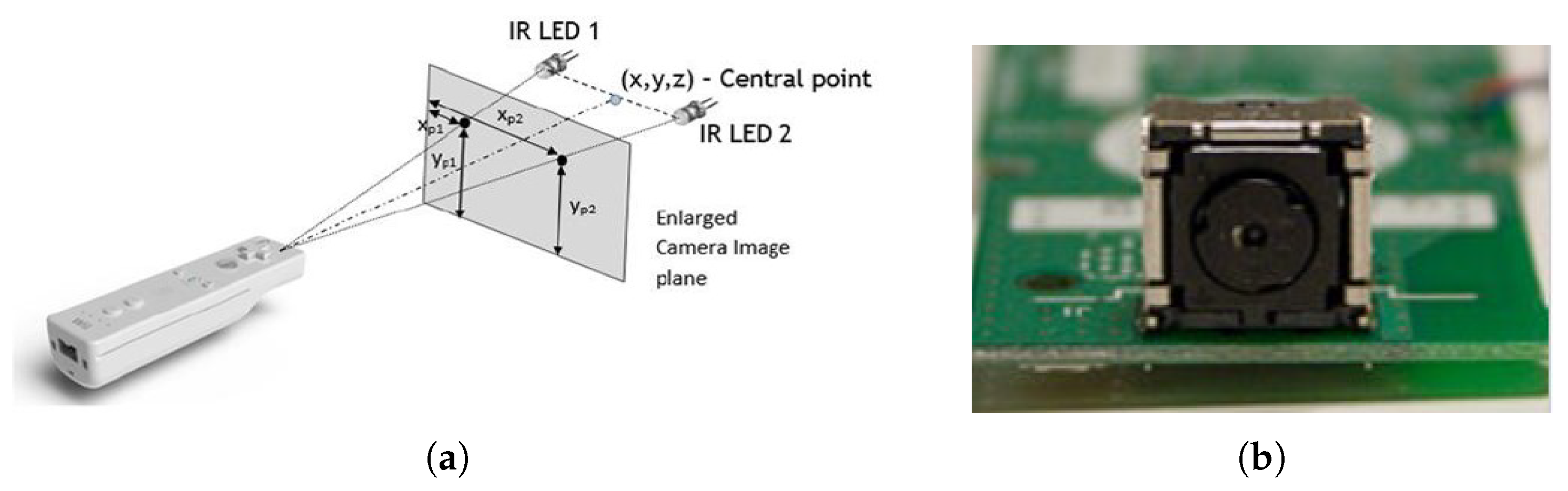
The innovative interactive technology of the Nintendo Wii remote (or Wiimote interchangeably), shown in
Figure 1a, has led to the Wii console being a game-changer in console generation with its first release in 2006. The Wiimote, a handheld device, consists of a speaker, a vibrator, an accelerometer, wireless Bluetooth connectivity, and a high-speed IR camera. The IR camera module (
Figure 1b) in the Wiimote includes prebuilt-in image processing to detect up to four IR light sources with high speed (100 Hz), whereas most of the other cameras have a speed of 30 Hz, which may further down due to post-image processing. Moreover, the Wiimote camera is cost-effective compared to other high-resolution cameras.
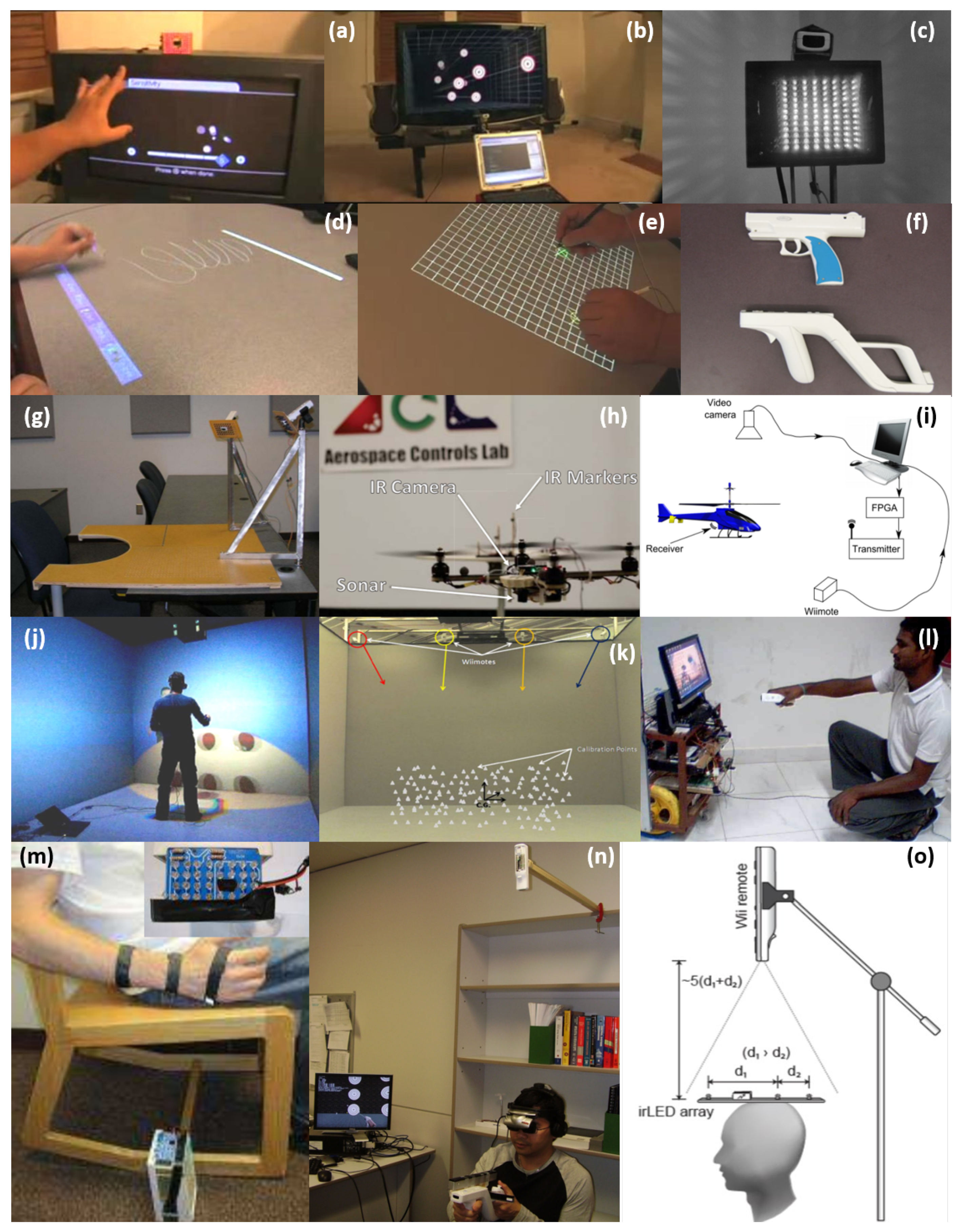
Aside from the Wii console’s market success, the Wii remote is widely used due to its capability for many applications including (a) finger tracking; (b) head tracking for VR (virtual reality) displays; (d), (e) an interactive whiteboard in [
1]. Other applications include (c) an IR-optical tracking system [
2]; (f) an IR gun [
3]; (g), (m) rehabilitation devices [
4,
5]; (h) a quadcopter application [
6]; (i) small UAV tracking [
7]; (j) cave-like environment VR [
8]; (k) automated assembly [
9]; (l) human-robot interaction [
10]; (n) head display for VR [
11]; and (o) indoor head tracking [
12] (see
Figure 2). Despite its broad applicability, all previous Wiimote applications are quite limited to indoor uses and no existing literature is found for outdoor applications owing to the obvious reason—sunlight that contains a wide range of spectrum including IR lights. In other words, the Wiimote camera cannot differentiate between the sunlight and the target IR light source. In this paper, we aim to challenge this problem by developing a practical method that realizes the Wiimote IR camera being used for outdoor target positioning.
Previous efforts using IR light sources for object positioning include the implementation of amplitude-modulated infrared lights [
13,
14], where a small-size optical sensing device is developed in these studies to estimate the relative position between the sensor and active markers. Small and cheap active infrared light emitting diodes (LEDs) flickering at two different frequencies are used to measure azimuth and elevation angles inspired by visual acuity in insects. More recently, infrared-based target positioning systems are developed in [
15,
16,
17], albeit in a slightly different way with various applications. These methods used infrared LEDs (or beacons) for accurate and robust pose estimation of a target object. Unfortunately, the aforementioned studies are all developed for indoor use and hence, it is not applicable to outdoor applications. A similar idea for outdoor target localization is introduced in [
18], where ultraviolet LED markers are used instead of IR LEDs. In this research, it is claimed that the ultraviolet light in the normal sunlight is significantly less intense and thus, the natural environments are normally too dim to prevent the detection from the camera. However, no experimental results to support this argument is provided in an extreme weather condition.
To discriminate an IR beacon from sunlight interference, we introduce a signal modulation technique that generates a certain pattern encoded in the IR beacon by manipulating IR LEDs’ on/off behavior. The Wiimote IR camera only looks for this particular pattern, to distinguish it from sunlight interference. In addition to that, this paper also investigates the camera sensor overload issue, caused by an extremely bright condition. If the amount of light is more than a certain threshold, the camera’s sensor is overloaded and the camera cannot detect any IR light sources. To resolve this issue, we adopt a filter that acts as a dimmer. As no light source matches the intensity of the direct sunlight, we consider the scenario that the IR camera does not directly stare at the sun. The irradiance of the sunlight reflection is then analyzed to assure that the IR light source provides enough brightness to overcome it. The proposed signal modulation technique is developed for the Wiimote IR camera; however, it can be also applicable and extensible to any generic IR cameras that can detect a certain spectrum of IR light in wavelength. It is expected that the proposed method can be used for outdoor applications such as drone precision landing for package delivery and battery recharge in a docking station. In this case, GPS-only information is not precise enough (GPS accuracy of within 30–500 cm according to [
19,
20]) or some areas, such as dense urban areas with tall buildings may have poor or no GPS signals. Consequently, the proposed algorithm will be a great alternative in such a scenario.
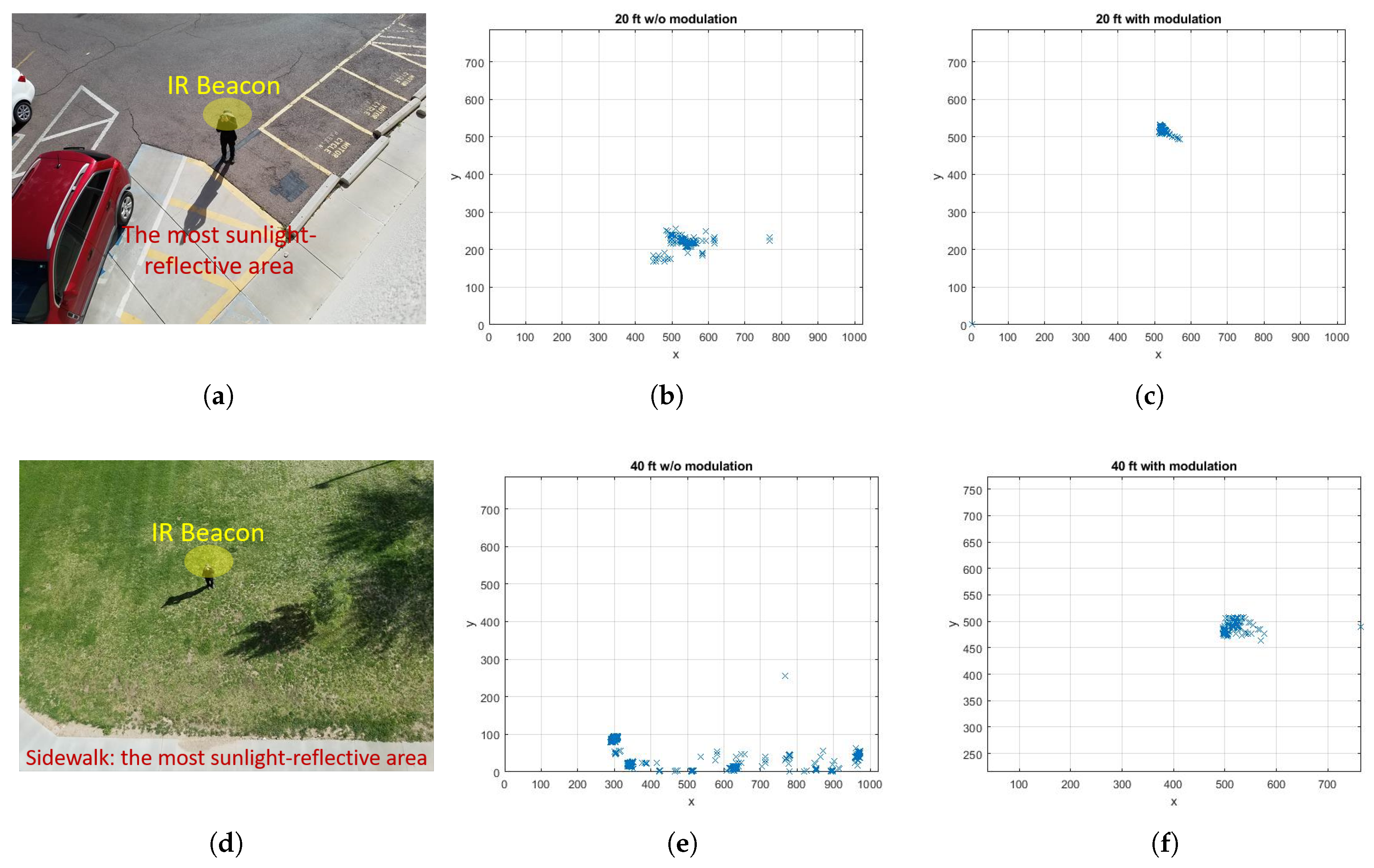
Various experiments are conducted to validate the proposed method as well as to test its practicality. The results for different distances with two different environments are provided in the Experiments section. The result verifies that the Wiimote IR camera can be used to detect the IR light source up to 18.3 m (60 feet) away even under the sunny weather condition.
2. Experimental Setup
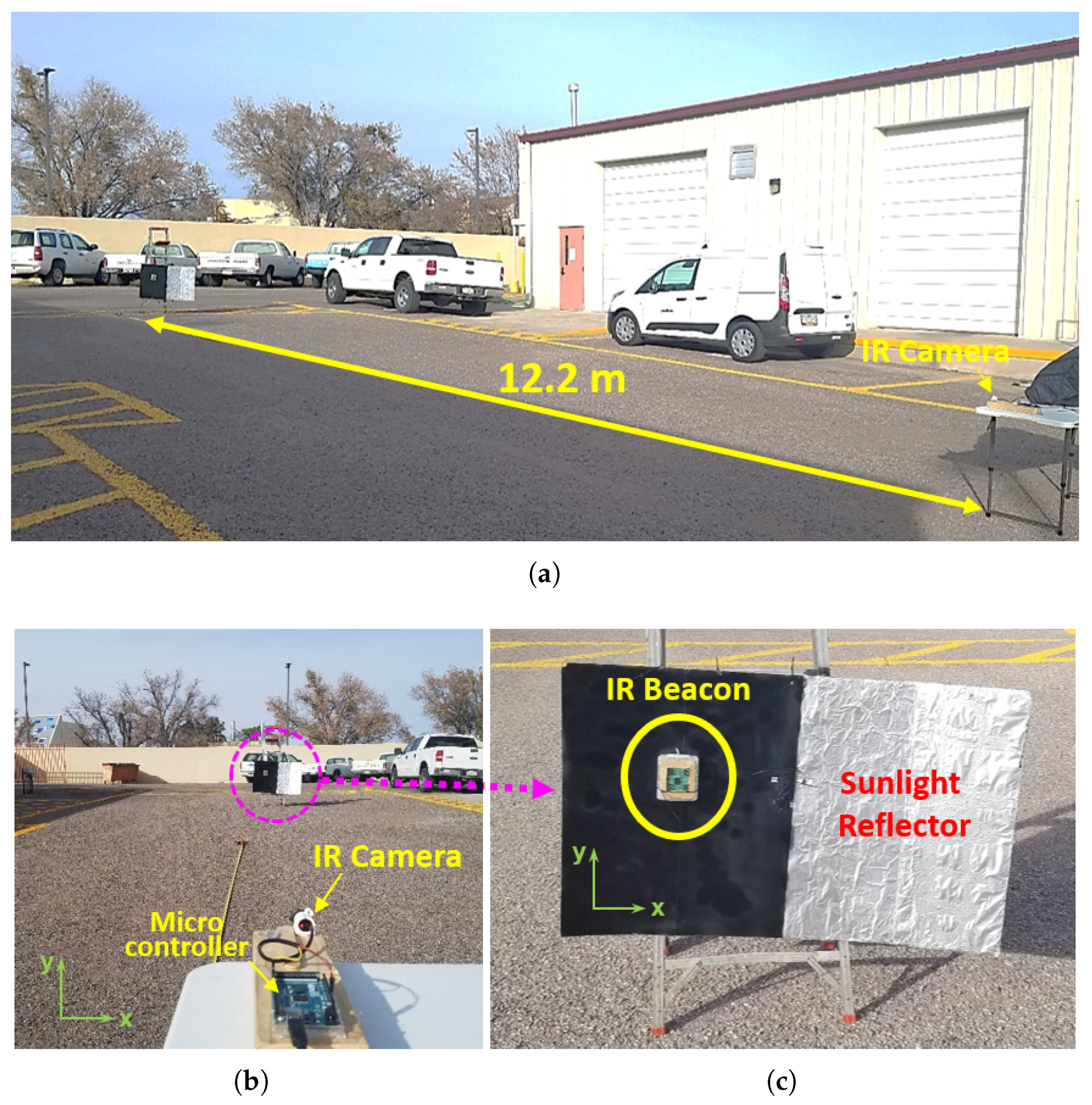
In this section, the experimental setup is introduced for target positioning using the Wiimote IR camera. This section is composed of two subsections—IR camera and IR beacon. Each subsection delivers detailed descriptions and information for each unit.
2.1. IR Camera
The Nintendo Wii Remote has a PixArt IR camera which has a resolution of 1024 × 768. The Wiimote includes a 128 × 96 monochrome camera with a built-in image processing that can track up to four IR light sources (or equivalently blobs). The IR camera has an IC communication interface which can be easily accessed by microcontrollers. The data that can be extracted for these blobs includes the two-dimensional image plane coordinate, the size of each blob, and their intensities. The position data from the camera has the form of a byte (0–255). This needs to be converted to readable data. For locations, blobs are plotted on a two-dimensional plane with a range of 0–1023 for the X-axis and 0–767 for the Y-axis. Although the camera can track any bright object, the Wiimote has a plastic high-low pass filter in front of the camera’s lens enabling the camera to focus on detecting 940 nm of an IR light. With the filter applied and by default, the camera can detect an IR emitting object up to about 6.1 m (20 ft) away theoretically; however, this can change with the size and intensity of the light source. The camera has a viewing angle of 33 degrees horizontally and 23 degrees vertically.
2.1.1. Camera Initialization
According to site WiiBrew.org [
21], a wiki dedicated to homebrew on the Nintendo Wii, the Wiimote camera can be initialized by sending the data to the specified memory address through the I
C communication protocol. The Wiimote camera has three different modes—basic, extended, and full mode. The camera mode can be changed by sending pre-specified value to the memory address. Although each mode provides different types of data, the extended mode is used in this research, which provides
X and
Y locations of each of the four IR light sources as well as a rough size of them.
2.1.2. Camera Sensitivity
The code for changing the camera’s default sensitivity, specifically for detecting 940 nm sources of light, requires initializing more registers. In addition to initializing the Wiimote’s IR camera, a specific value is assigned to different registers for different sensitivity settings. The formal procedure to change the sensitivity setting is provided in the
Supplementary Material.
The effect of changing the camera’s sensitivity values is similar to holding a dark lens in front of the camera. The darker the lens, the less sensitive it is to other wavelengths of IR light and interference. A setting that lessens the sensitivity will improve the camera’s ability to detect 940 nm sources of light, and increase the distance the camera can see. The tradeoff is that a lower sensitivity will make the camera more prone to IR interference.
2.1.3. ND (Neutral-Density) Filter
If reflections from the sun are too strong, the camera will be exposed to too much sunlight, causing the overload of image sensors. This is mainly due to the effect of overloading the IR camera’s photo-receptors. This issue cannot be resolved even with the least sensitivity setting provided above. Differently from the generic cameras as in most smartphones, the Wiimote IR camera does not include the auto-brightness feature and hence, it cannot adjust the brightness automatically. This implies that the IR camera does not detect any infrared sources if the environment is extremely bright. To avoid this issue, several tests were conducted with a grayed out piece of plastic placed in front of the IR camera. It is observed that more consistent data is collected even with extremely hot spots from sunlight reflections. With a scientific endeavor to accurately test the dimmer effect, an ND filter, a filter that reduces or modifies the intensity of all wavelengths, or colors, of light equally, is adopted. The fractional transmittance, which is the fraction of the optical power transmitted through the filter, is then computed as follows.
where
and
I are the original and filtered intensity, respectively and
d is an optical density determined by the ND filter ratings. For the experiments, an ND
that has the optical density
was used. This corresponds to a
of the fractional transmittance when a single layer is used.
2.2. IR Beacon
The IR beacon consists of several clusters of IR LEDs, an electric current amplifier, and a microcontroller to control the LEDs’ blinking behavior. Not only the configuration of the IR beacon but also the required number of LEDs in the cluster is introduced based on the sunlight intensity analysis.
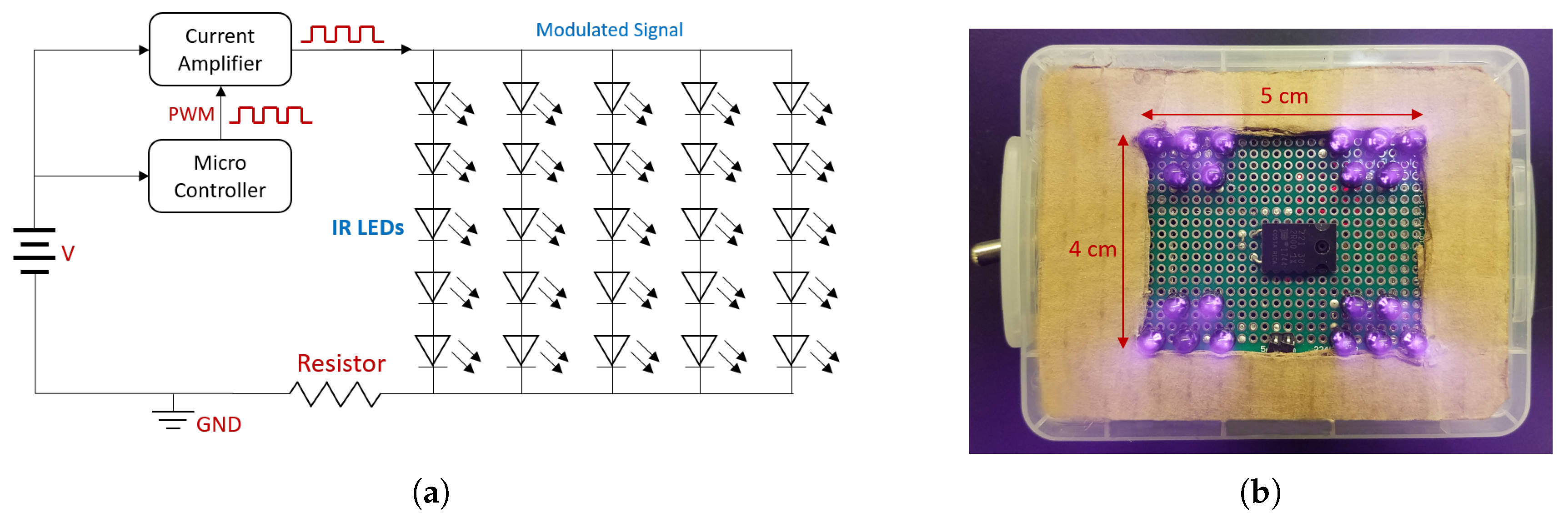
2.2.1. IR LED and Electric Circuit
As the Wiimote’s IR camera tracks 940 nm light better than the other wavelengths of IR lights, the IR beacon is constructed with a large bundle of 940 nm IR LEDs. The beacon needs to be bright enough so that it can overcome the sunlight reflections’ intensity and can be detected by the IR camera. Four clusters of five LEDs are attached to a solder board as shown in
Figure 3. The LEDs are positioned such that all LEDs are parallel to one another to ensure that the path of the light intersects with one another. The LEDs are controlled by the microcontroller—Arduino nano version with an electric current amplifier. Although the prototype is small enough with the size of an adult’s palm, this electric circuit can be further improved and miniaturized with electric components such as a crystal oscillator and a low-power op-amp for practicality in the future.
For reference, the specification of the LED used in this research is provided in
Table 1.
2.2.2. IR Beacon’s Intensity Analysis
As the Wiimote IR camera can detect up to four IR light sources, the IR beacon cannot be picked up by the IR camera, if the intensity of the IR beacon is not strong enough during outdoor experiments. Thus, it is necessary to analyze the required intensity of the IR beacon to overcome that of sunlight reflections. If the IR beacon can be seen by the Wiimote IR camera even in the worst-case scenario (i.e., when the weather is extremely sunny), then the IR camera can detect the IR beacon in any weather conditions and at any time. In what follows, the required intensity of the IR beacon is analyzed.
In everyday life, our visual reception is based on the effect produced by the light source at the surface of the surrounding objects. This means that we are interested in the amount of radiated energy, which reaches the observed surface element in a unit time. The irradiance
E expresses radiation power
(flux) received by a unit area
A of the illuminated surface with the unit of
W/m
as follows:
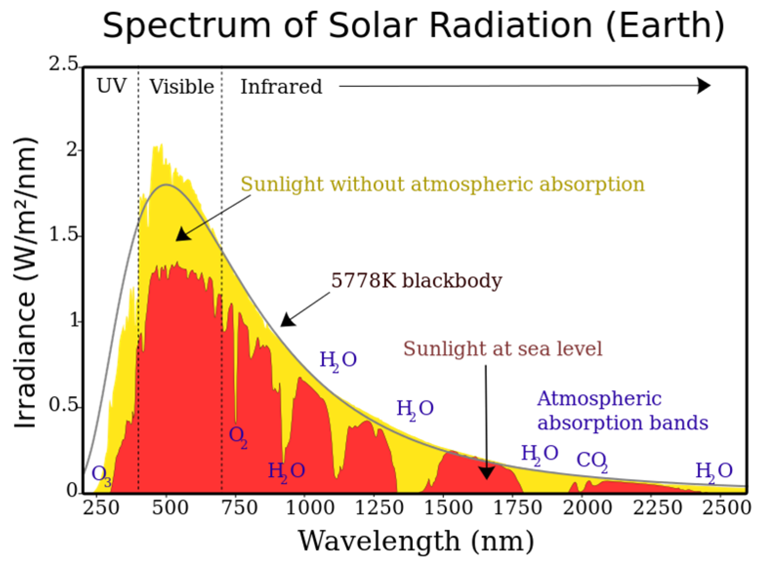
The spectrum of solar radiation shown in
Figure 4 indicates that the sunlight irradiance for the IR wavelength of 940 nm is approximately 750
W/m
at sea level. Some portions are absorbed by the Earth’s surface while the rest is reflected. Although various factors affect the reflectance of sunlight from the Earth’s surface, terrestrial
albedo that describes the percentage of diffusely reflected sunlight out of the total solar radiation can be adopted to estimate the irradiance of the sunlight from the Earth’s surface. The albedo ranges between
and
in most land areas according to [
22]. In the worst case that is an albedo of
, the irradiance of sunlight reflection from surfaces is computed by
/m
.
From
Table 1, each IR LED used here has the radiant flux of
= 75 m
W, resulting in the total radiant flux of
= 75 m
ea
with 20 LEDs. Based on the beacon area
= 0.05 m × 0.04 m = 0.002 m
from
Figure 3b, the irradiance of the beacon is computed by
=
= 750
W/m
, which is
times greater than that of the sunlight reflection from surfaces. Based on this analysis, it is guaranteed that the IR camera can at least detect the IR beacon even under the extremely bright weather condition.
3. Signal Modulation
The IR beacon’s intensity can be bolstered by using high-powered LEDs. However, this does not necessarily imply that the IR beacon is uniquely separated from surfaces reflecting the sunlight. A remedy proposed here is to apply a signal modulation to the IR beacon, where the signal modulation is a process of varying one or more properties of a waveform.
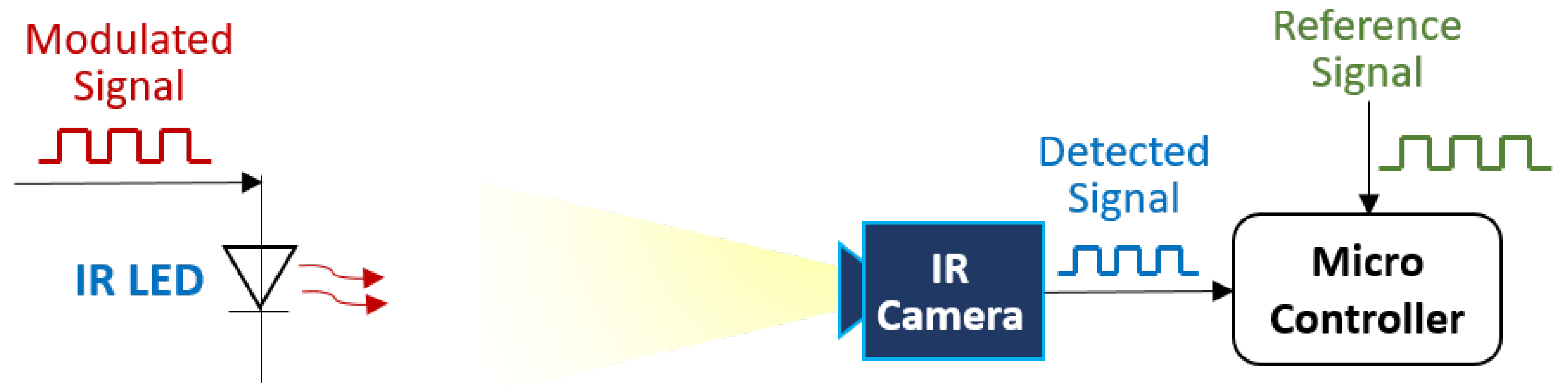
3.1. Signal Modulation
By controlling the IR LEDs’ on/off behavior in the transmitter signal, a specific pattern is encoded. Then, the waveform can be read by the IR camera and decoded by a microcontroller as a serial bitstream. A schematic of the signal modulation is presented in
Figure 5 to illustrate the process.
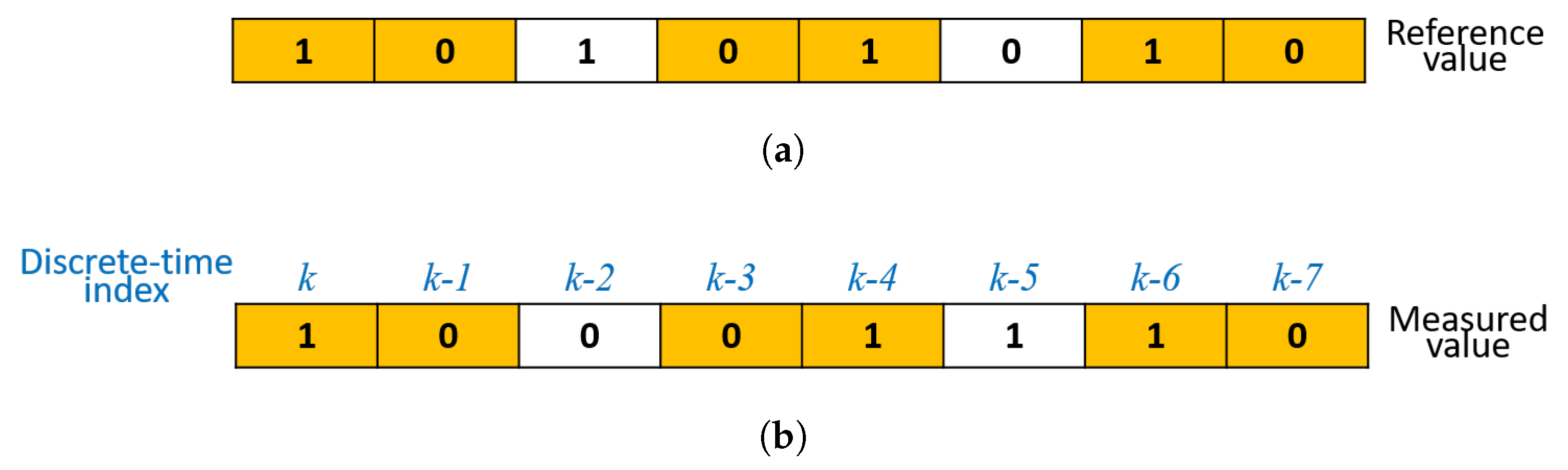
The IR camera detects modulated signals from the IR beacon—1 being HIGH and 0 being LOW for the IR beacon’s state, followed by a comparison between the measured (or detected) and the reference signal by a microcontroller. The example below shows the binary signal array that can be used to compare the reference and measured values
Figure 6.
In each loop counted by a discrete-time step of the microcontroller, the previous values are shifted to the right by one and the previous right-most bit is dropped. Then, the measured signal at the current discrete-time step is saved in the left-most bit of the measured binary signal array.
Notice that the reason for shifting the previously recorded values, instead of waiting for the whole signal array to be filled with the measured value, is to maximize the comparison rate. In this case, the frequency f is computed by , where T is the period, calculated from the loop time or the time taken between k and . On the other hand, the frequency f becomes, in the case of an n-bit signal array, when waiting for the measured signal array being filled with n numbers of measurements, which will seriously slow down the frequency. Thus, the comparison can be carried out in each loop time by the proposed method.
3.2. Jaccard Index—A Metric to Measure Signal Matching Bits
To compare the similarity between the measured and reference array, the Jaccard index, a statistic to gauge the similarity and diversity of sample sets, is employed. The Jaccard index
for two sets
A and
B is defined by
which always satisfies
. In the signal matching application, the Jaccard index can be computed as follows:
where
M and
R in
stand for the measured and reference signal set, respectively.
One needs to set up a threshold value, , for a distinction between the IR beacon and reflections. If the current Jaccard coefficient is greater than or equal to , then the measured data can be regarded as the IR beacon. Increasing may lead to less detectability of the beacon while decreasing can make the IR camera more prone to interference from sunlight reflections.
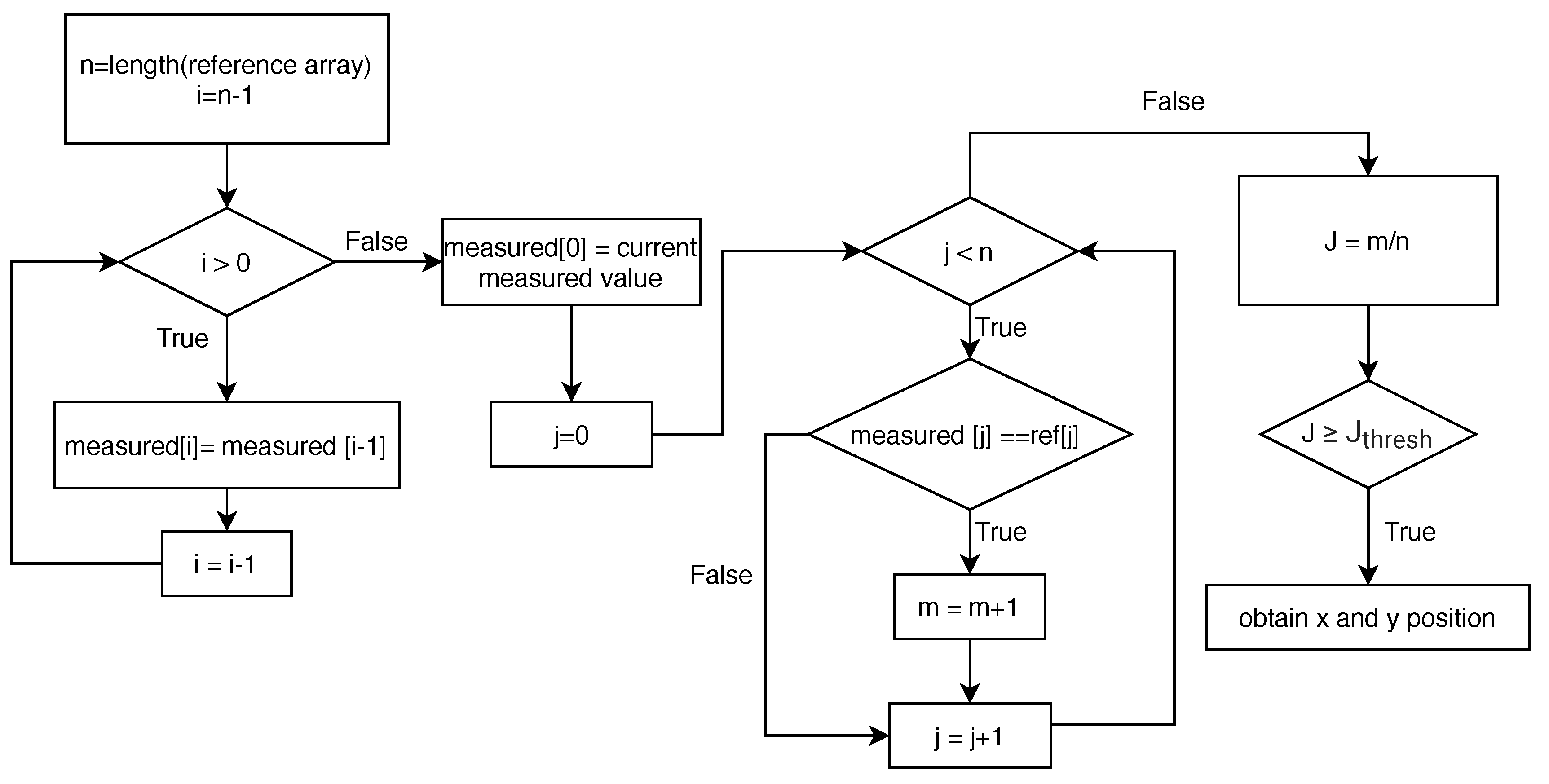
3.3. Algorithm
A Pseudocode is provided in Algorithm 1 with the case that the reference array is given by ref = {0, 1, 0, 1, …}, i.e., alternating zero and one with each other. The most general case for an arbitrary reference array can be induced in a similar manner.
| Algorithm 1 Pseudocode for Signal Modulation | |
| 1: initialize n, ref[n], measured[n], , J, | |
| 2: | |
| 3: while do | |
| 4: measured[i] ← measured[] |
▹ Shift the data array to the right by one |
| 5: | |
| 6: measured[0] ← current measured value (i.e., 0 or 1) | |
| 7: | |
| 8: while do | |
| 9: if measured[j] == ref[j] then | ▹ Compare the bit |
| 10: | |
| 11: | |
| 12: | |
| 13: if then | ▹ Signal matching case |
| 14: retrieve x and y position | ▹ Obtain x and y position information | |
Several parameters are set including a total number of bits for the signal modulation array, n, the reference array, ref[n], and the measured array, measured[n]. Furthermore, the symbols for the Jaccard index, J, and the threshold value, , are assigned by the user. The integer m is defined for the comparison of J and .
The lines from 3 to 6 in Algorithm 1 is given for the update of the measured array, a size of n, by shifting the previous values by one and save the current measured value to measured [0]. Once again, it is unnecessary to completely fill out the measured array, which takes a total of n steps, leading to a waste of time and hence, a slow frequency. The proposed algorithm for the signal modulation can be used to compare the difference between the measured and reference array based on the Jaccard index at each time step with faster implementation. The bit-by-bit comparison is provided in the lines from 8 to 11 in Algorithm 1. If the Jaccard index is greater than or equal to the predefined threshold value, , then retrieve the position information because it indicates that the detected signal is the IR beacon, not the sunlight interference.
Alternatively, a diagram showing the process of the proposed method is provided in
Figure 7, to clearly describe the flow of the signal modulation algorithm.
5. Conclusions
In this paper, we investigated the use of the Wiimote IR camera for outdoor target positioning. To avoid interference from sunlight reflections, the signal modulation technique is proposed. This enables the IR camera to filter out the interference, leading to the successful detection of the IR beacon. The irradiance of the sunlight reflection was also analyzed for the IR beacon to overcome it. Furthermore, an ND filter was introduced for the camera sensor overload issue. To validate the proposed method, several test results are provided. From the experimental results, it is proven that the proposed method can be used to detect an outdoor target up to 18.3 m (60 ft) away from the IR camera even in sunny weather conditions. The frequency of the target detection is achieved more than 30 Hz for both 6.1 m (20 ft) and 12.2 m (40 ft) cases. Thus, it is shown that the proposed methods are practical in terms of low-cost, fast, and computationally efficient outdoor target positioning. This leaves open the possibility of the proposed signal modulation algorithm being implementable to broad applications, where accurate positioning of an outdoor target is necessarily required such as drone precision landing.


