Abstract
More accurate navigation systems are always required for autonomous unmanned underwater vehicles (AUUV)s under various circumstances. In this paper, a measuring complex of a heavy unmanned underwater vehicle (UUV) was investigated. The measuring complex consists of an inertial navigation platform system, a Doppler lag (DL) and an estimation algorithm. During a relatively long-term voyage of an UUV without surfacing and correction from buoys and stationary stations, errors of the measuring complex will increase over time. The increase in errors is caused by an increase in the deviation angles of the gyro platform relative to the accompanying trihedron of the selected coordinate system. To reduce these angles, correction is used in the structure of the inertial navigation system (INS) using a linear regulator. To increase accuracy, it is proposed to take into account the nonlinear features of INS errors; an adaptive nonlinear Kalman filter and a nonlinear controller were used in the correction scheme. Considering that, a modified nonlinear Kalman filter and a regulator in the measuring complex are proposed to improve the accuracy of the measurement information, and modification of the nonlinear Kalman filter was performed through a genetic algorithm, in which the regulator was developed by the State Dependent Coefficient (SDC) method of the formulated model. Modeling combined with a semi-natural experiment with a real inertial navigation system for the UUV demonstrated the efficiency and effectiveness of the proposed algorithms.
1. Introduction
For performing underwater work as scientific research and practical implementation, unmanned underwater vehicles (UUV)s are widely used. The most famous UUV series are as follows: “Remus” (Hydroid, USA), “Autosub 6000” (UK), and “GAVIA” (Russia) [,]. With the help of UUVs, search operations and the inspection of sunk objects and pipelines are carried out, information warfare by creating false targets and interference is conducted, and UUVs are implemented for environmental monitoring, etc. Normally, UUVs can be classified according to the mass of the vehicle: micro, small, medium and heavy classes [,]. For the study of ice conditions, the performance of hydrographic work in the Arctic, as well as the fulfillment of special tasks in the interests of defense agencies, heavy autonomous unmanned underwater vehicles (AUUV)s (not towed UUVs) are applied. During the operation of UUVs, their exact orientation in space and knowledge of navigation parameters are very important. For this purpose, inertial navigation systems (INS), sonars, Doppler lags, etc., are installed on AUUVs [,,]. For example, the UUV GAVIA is equipped with a strapdown INS and the WN-300 Doppler lag, which are combined into a measuring complex (MC). The INS and lag signals are processed together using the Kalman filter [,,,].
When the UUV is working under ice fields in the Arctic, there is no possibility of periodic ascent to the surface of the sea; thus, INS correction from a gyro-stabilized platform (GSP) is not provided. In the case of long-term autonomous navigation with the use of a strapdown INS, errors increase over time due to the instability of sensitive elements. Moreover, when UUVs perform maneuvers to complete tasks with long-term autonomous navigation, even for platform INS, errors will reach large values. This is due to an increase in the deviation angles of the gyro-stabilized platform (GSP) relative to the accompanying coordinate system (SC). Even with the correction of INS from a lag and information processing by the Kalman filter, errors of the navigation information increase as the model of INS errors in the Kalman filter becomes inadequate for the real process.
Considering the prospective applications, scientists have been interested in AUUVs and all the particular constraints in different media have been formulated into mathematical problems. Wu et al. [] generated the optimal paths based on the Particle Swarm Optimization (PSO) algorithm and the Kalman filter to finish an underwater target strike mission; Batista et al. [] proposed a filtering method with applications to estimate the linear motion of underwater vehicles, taking into considertion both environmental disturbances and realistic measurement noise; Jens et al. proposed a sensor-based method with hybrid dynamical systems for underwater navigation; further, the observer performance should be evaluated in closed-loop with a feedback controller, an attitude observer, and a guidance scheme []. In order to improve the accuracy of navigation definitions of heavy UUVs for long-term autonomous operation, it is advisable to use more accurate nonlinear error models of INS in the algorithmic support. Accordingly, the nonlinear Kalman filter (NKF) can be applied in the MC [,].
In this work, the novelty lies in the application of algorithmic correction in the structure of the INS. Correction algorithms are proposed: an adaptive nonlinear Kalman filter and a nonlinear state regulator. The reduced regulator for INS correction in a nonlinear statement of the problem has been developed, and the Dependent Coefficient (SDC) method of transformation of the nonlinear INS error model is considered for the synthesis of the regulator; a correction in the structure of INS is proposed and used with the help of a regulator [,]. A reduced regulator and an adaptive regulator for the INS correction using linear models of INS errors were formulated, and the linear models of INS errors quite roughly describe the process of real INS errors. Moreover, the efficiency of the proposed INS correction method was demonstrated by mathematical modeling and simulation according to the semi-natural experiment.
The paper is organized as follows: In Section 2, the nonlinear errors model of INS for UUVs is introduced, as well as the platform of INS. The correction of navigation systems by a nonlinear Kalman filter modification is presented in Section 3, which provides the algorithmic support for the INS correction process of UUVs. Simulation and validation through experiments of the proposed method are performed in Section 4, and the discussion and analysis of results are presented later. Section 6 concludes the paper.
2. Nonlinear Errors Model of INS
The main measurement complex system of the studied UUV is INS; the platform INS consists of accelerometers installed on a GSP [,]. INS has errors which are caused by the drift of gyroscopes, accelerometers and other perturbing factors, and INS errors increase over time and could get large values. The platform coordinate system (CS) differs from the navigation CS in the misalignment angles , and . These angles can be used as indicators of system errors, considering the fact that the physical axes of the platform must coincide with the platform axes. Thus, the transition matrix from the navigation CS to the platform can be represented as [,,,]
where denotes the platform trihedron; LL denotes the geographic trihedron.
The absolute angular velocity in the platform CS can be formulated using the angular velocity in the navigation CS and the derivatives of the mismatched angles.
The errors of INS horizontal accelerometers are obtained from the equations as follows:
where is zero offsets of accelerometers and is errors from scale coefficient.
Then, substituting Equation (1) into Equation (3), the error equations of INS can be obtained [,]:
where ; ;
where , , are velocities of the UUV in navigation CS and their errors; and represent latitude and its error, respectively, U is the angular velocity of the Earth, and here, D is the nonlinear part.
In Equation (4), the matrix Φ determines the relation between the components of the state vector x. W is input noise, including dominant external disturbances. D is a matrix including nonlinear terms of the second order of smallness [,]. The dominant elements that determine the dynamics of x are selected in matrix Φ.
In the algorithmic support of measuring systems, which is implemented on the board of the underwater vehicle, more simple error models of INS are used [,]. For the only horizontal channel, the nonlinear error model of INS has its form as follows:
where is the state vector, is the matrix of the object and is input noise.
where denotes error in determining the velocity, represents angles of horizontal deviation, is drift velocity, is zero offset, and is white noise.
In order to compensate for the INS errors, these errors should first be evaluated. Estimation of errors of INS is carried out using estimation algorithms [], and one of the most common methods is the Kalman filter. Taking nonlinear components into account, the nonlinear Kalman filter (NKF) is used to estimate the INS errors. However, the INS error model in the NKF may not be adequate for the actual process of the changing the INS errors, especially when performing UUV maneuvers. Thus, the identification of the INS error model in the NKF should be considered.
4. Experimental Study and Validation
In order to conduct an experiment with a real INS, the following steps should be considered and performed:
- Install the INS platform on a fixed base, and enable INS. Since the INS is stationary, the output signal is an INS error.
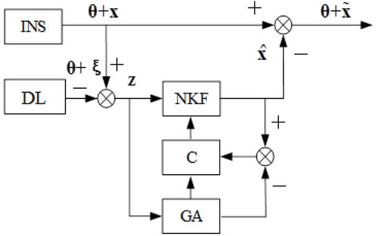
- Generate measurements for the Kalman filter z in accordance with Figure 1, and a Doppler lag error is simulated using a random number sensor. The signal is smoothed at the interval T = 12 s.
- Evaluate the INS errors by means of the algorithm in Figure 1. In the Kalman filter in the matrix F, the following numerical values are used: R = 6,370,000 m, g = 9.8 m/s2, the average frequency of random drift change is µ = 2 × 10⁻⁴/s. In Equation (10), during the formation of the covariance matrix of the Kalman filter measuring noise, errors of the Doppler lag v are assumed to be white noise with an intensity equal to 0.015 m/s, and in Equation (11) in the matrix Q, the zero offset of the accelerometer is assumed to be a constant value B = 5 × 10⁻⁴ m/s2; the dispersion of external perturbation on the gyroscope ηk is assumed to be 10−16.
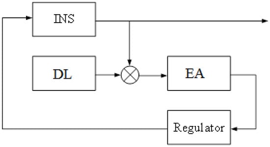
- Form the control u = , and submit a signal u to the input of INS with Figure 2. The control signal is forwarded to the input of first integrator and the input of the torque sensor.
The results of the operation modeling of MC with a control algorithm and MC with a nonlinear control algorithm are presented in Figure 3, Figure 4, Figure 5 and Figure 6.
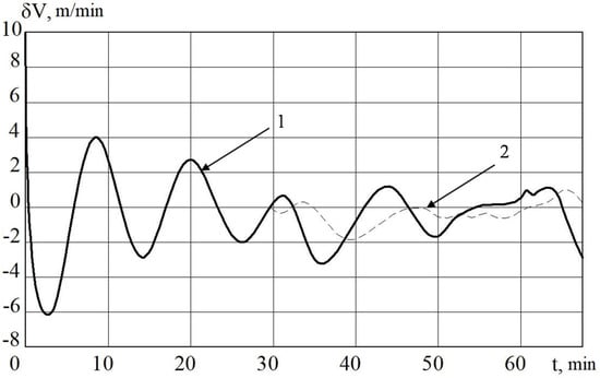
Figure 3.
INS errors in determining the velocity with regulator (1) and non-linear regulator (2).
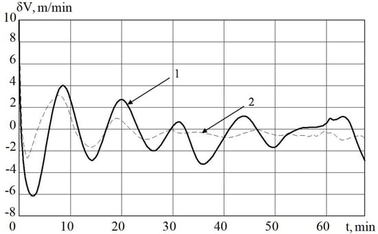
Figure 4.
INS errors in determining the velocity MC with regulator (1) and non-linear SDC regulator (2).
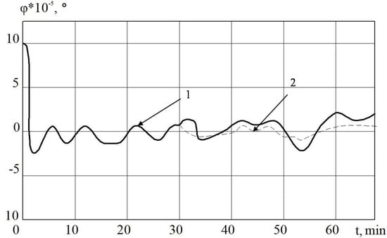
Figure 5.
The deviation angle of the gyro-stabilized platform (GSP) in INS from the horizon plane when using MC with a regulator (1) and a non-linear regulator (2).
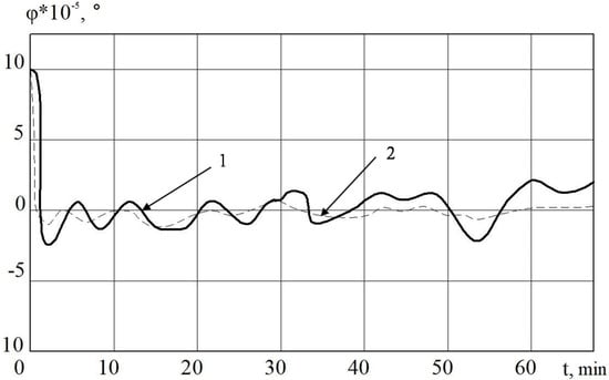
Figure 6.
The deviation angle of the GSP in INS from the horizon plane when using a measuring complex (MC) with a regulator (1) and a non-linear SDC regulator (2).
In Figure 3 and Figure 5, it is shown that the errors of the MC in INS with the linear and nonlinear models that were used in the regulator at the first stage almost coincide. The difference begins to be clearly observed with 30 min of MC operation. Based on the results of mathematical modeling, it can also be seen that it is possible to improve the accuracy of error calculation in determining velocity by 10%, and deviation angles of GSP by 15%.
For comparison and validation, modeling according to a laboratory experiment was carried out using a nonlinear Kalman filter. The simulation results are presented in Figure 7, Figure 8 and Figure 9.
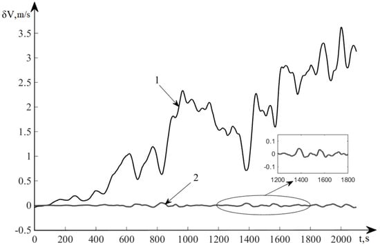
Figure 7.
TS060K Errors for determination of velocity.
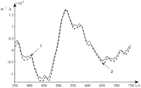
Figure 8.
Estimation results of deviation angles of the GSP.
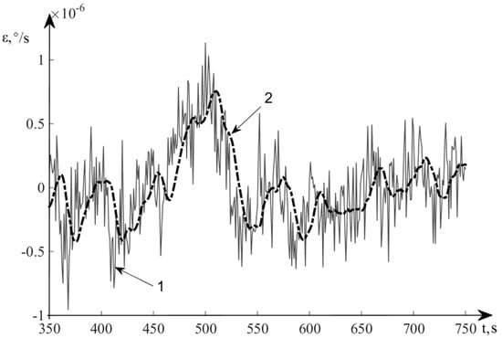
Figure 9.
Estimation results of velocity drift of the GSP.
Figure 6 and Figure 7 show the results of modeling the INS error in autonomous mode and with correction obtained by the control algorithm. Line 1 represents the error of INS in determining the speed in autonomous mode (without correction), and line 2 shows the INS error in determining the velocity after correction using the developed nonlinear control algorithm.
In Figure 8, line 1 denotes the deviation angles of a real system GSP and line 2 represents the estimation of deviation angles of the GSP.
In Figure 9, line 1 denotes the velocity drift of a real system GSP, and line 2 represents the estimation of deviation angles of the GSP.
5. Discussion and Analysis of Simulation Results
Here, a set of algorithms was developed for MC, including a nonlinear control algorithm that was used for error compensation in the structure of INS, and they can work for a long time without correction from stationary navigation stations. In the synthesis of the control algorithm, the method of SDC representation of nonlinear models was used. The efficiency and effectiveness of the developed algorithms were demonstrated by means of mathematical modeling and simulations according to data results of the semi-natural experiment within the TS060K system (Inertial Navigation System Ц060K, Russia).
The proposed MC correction algorithms increase the accuracy of navigational determinations of UUVs during long-term voyages in the underwater state and without correction from stationary stations and buoys. While the proposed algorithms have applied a priori models in the regulator, which may not accurately describe the changing process of INS errors, in general, the SDC method has limitations in its application [,], and not every model can be represented by the SDC method. These aspects limit the application of the developed algorithmic software in other dynamic objects.
6. Conclusions
In this paper, the measurement complex of an autonomous heavy UUV designed for long voyages without surfacing on the sea surface was developed. The MC consists of an INS platform, Doppler lag, NKF of modified GA, and a nonlinear controller for correction in the structure of INS. Synthesis of the reduced regulator was carried out using the SDC method.
With the help of a regulator, INS errors were reduced during operation for a long time without correction from stationary navigation stations, GPS and beacons. In comparison with the well-known methods (linear optimal and adaptive regulators in the INS correction scheme), the simulation results confirm the advantages of the proposed method for increasing the accuracy of INS. Therefore, the method proposed in this paper allows an increase of the accuracy of navigational determinations of UUVs during long-term (more than 3 hours) autonomous navigation.
Author Contributions
In this research work, the individual contributions of authors are specified as follows: conceptualization, D.C.; methodology, K.A.N. and M.S.S.; validation, M.S.S.; investigation, K.A.N. and M.S.S.; writing, original draft preparation, D.C.; writing, review and editing, D.C.; funding acquisition, D.C. All authors have read and agreed to the published version of the manuscript.
Funding
This work was supported by the Program of Introducing Talents of Discipline to Universities in China (Program 111, No. B 16025) and NSFC (Natural Science Foundation of China) (No. 51905272).
Acknowledgments
The authors would like to thank the editors and the anonymous reviewers for their valuable comments and constructive suggestions.
Conflicts of Interest
The authors declare that there is no conflict of interest regarding the publication of this paper. The authors also declare that they do not have any commercial or associative interest that represents a conflict of interest in connection with the work submitted.
References
- Whitcomb, L.L. Underwater robotics: Out of the research laboratory and into the field. In Proceedings of the 2000 ICRA. Millennium Conference. IEEE International Conference on Robotics and Automation. Symposia Proceedings IEEE, San Francisco, CA, USA, 24–28 April 2000; Volume 1, pp. 709–716. [Google Scholar]
- Diorio, R.A.; Walter, C.R.; Tintner, R.J. Encapsulated Underwater Vehicle Modules. U.S. Patent 11,465,773, 21 February 2008. [Google Scholar]
- Bocharov, L. Uninhabited underwater vehicles: State and general development trends. Part 2. Electron. Sci. Technol. Bus. 2009, 8, 88–93. [Google Scholar]
- Rhif, A. A review note for position control of an autonomous underwater vehicle. IETE Tech. Rev. 2011, 28, 486–492. [Google Scholar] [CrossRef]
- Chen, D.; Neusypin, K.; Selezneva, M.; Mu, Z. New Algorithms for Autonomous Inertial Navigation Systems Correction with Precession Angle Sensors in Aircrafts. Sensors 2019, 19, 5016. [Google Scholar] [CrossRef] [PubMed]
- Proletarsky, A.V.; Neusypin, K.A.; Selezneva, M.S. Method for Improving Accuracy of INS using Scalar Parametric Identification. In Proceedings of the 2019 International Russian Automation Conference IEEE, Sochi, Russia, 8–14 September 2019; pp. 1–4. [Google Scholar]
- Selezneva, M.S.; Neusypin, K.A.; Proletarsky, A.V. Navigation complex with adaptive non-linear Kalman filter for unmanned flight vehicle. Metrol. Meas. Syst. 2019, 26, 3. [Google Scholar]
- Julier, S.J.; Uhlmann, J.K. New extension of the Kalman filter to nonlinear systems. Signal Process. Sensor Fusion Target Recognit. VI Int. Soc. Opt. Photonics 1997, 3068, 182–193. [Google Scholar]
- Amsters, R.; Demeester, E.; Stevens, N.; Slaets, P. In-Depth Analysis of Unmodulated Visible Light Positioning Using the Iterated Extended Kalman Filter. Sensors 2019, 19, 5198. [Google Scholar] [CrossRef] [PubMed]
- Gao, B.; Hu, G.; Zhu, X.; Zhong, Y. A Robust Cubature Kalman Filter with Abnormal Observations Identification Using the Mahalanobis Distance Criterion for Vehicular INS/GNSS Integration. Sensors 2019, 19, 5149. [Google Scholar] [CrossRef] [PubMed]
- Selezneva, M.; Proletarsky, A.; Neusypin, K.; Lifei, Z. Modification of the Federated Kalman Filter Using the Observability Degree Criterion of State Variables. In Proceedings of the 2019 26th Saint Petersburg International Conference on Integrated Navigation Systems (ICINS) IEEE, Saint Petersburg, Russia, 27–29 May 2019; pp. 1–3. [Google Scholar]
- Wu, Y. Coordinated path planning for an unmanned aerial-aquatic vehicle (UAAV) and an autonomous underwater vehicle (AUV) in an underwater target strike mission. Ocean Eng. 2019, 182, 162–173. [Google Scholar] [CrossRef]
- Batista, P.; Silvestre, C.; Oliveira, P. Optimal position and velocity navigation filters for autonomous vehicles. Automatica 2010, 46, 767–774. [Google Scholar] [CrossRef]
- Bremnes, J.E.; Brodtkorb, A.H.; Sørensen, A.J. Sensor-Based Hybrid Translational Observer for Underwater Navigation. IFAC-Pap. OnLine 2019, 52, 378–383. [Google Scholar] [CrossRef]
- Hostetler, L.; Andreas, R. Nonlinear Kalman filtering techniques for terrain-aided navigation. IEEE Trans. Autom. Control 1983, 28, 315–323. [Google Scholar] [CrossRef]
- Lefebvre, T.; Bruyninckx, H.; Schutter, J. Nonlinear Kalman Filtering for Force-controlled Robot Tasks; Springer: Berlin, Germany, 2005; Volume 19. [Google Scholar]
- Yang, G.; Chen, D.; Selezneva, M.; Neusypin, K. Development of the measuring complex with reduced regulator. J. Phys. Conf. Ser. 2019, 1311, 12–37. [Google Scholar] [CrossRef]
- Proletarsky, A. Nonlinear Information Processing Algorithm for Navigation Complex with Increased Degree of Parametric Identifiability. Recent Res. Control Eng. Decis. Mak. 2019, 199, 37–49. [Google Scholar]
- Tijing, C.; Emeliantsev, G.I. Study on the rate azimuth platform inertial navigation system. J. Southeast Univ. 2005, 21, 29–32. [Google Scholar]
- Goshen-Meskin, D.; Bar-Itzhack, I.Y. Unified approach to inertial navigation system error modeling. J. Guid. Control Dyn. 1992, 15, 648–653. [Google Scholar] [CrossRef]
- Salychev, O.S. Applied Inertial Navigation: Problems and Solutions; BMSTU Press: Moscow, Russia, 2004. [Google Scholar]
- Andreev, V.D. Theory of inertial navigation. In Autonomous Systems; Science: New York, NY, USA, 1966; p. 579. [Google Scholar]
- Andreev, V.D. Theory of inertial navigation. In Corrected Systems; Science: New York, NY, USA, 1967; p. 697. [Google Scholar]
- Kuzovkov, N.T.; Salychev, O.S. Inertial Navigation and Optimal Filtration; Mechanical Engineering: Moscow, Russia, 1982; p. 217. [Google Scholar]
- Shin, S.H.; Park, C.G.; Kim, J.W.; Hong, H.S.; Lee, J.M. Adaptive step length estimation algorithm using low-cost MEMS inertial sensors. In Proceedings of the IEEE Sensors Applications Symposium, San Diego, CA, USA, 6–8 February 2007; pp. 1–5. [Google Scholar]
- Rigatos, G.G. Nonlinear Kalman filters and particle filters for integrated navigation of unmanned aerial vehicles. Robot. Auton. Syst. 2012, 60, 978–995. [Google Scholar] [CrossRef]
- Shakhtarin, B.I.; Shen, K.; Neusypin, K.A. Modification of the nonlinear kalman filter in a correction scheme of aircraft navigation systems. J. Commun. Technol. Electron. 2016, 61, 1252–1258. [Google Scholar] [CrossRef]
- Elsheikh, M.; Abdelfatah, W.; Noureldin, A.; Iqbal, U.; Korenberg, M.; Noureldin, A. Low-Cost Real-Time PPP/INS Integration for Automated Land Vehicles. Sensors 2019, 19, 4896. [Google Scholar] [CrossRef] [PubMed]
- Koza, J.R. Genetic Programming: On the Programming of Computers by Means of Natural Selection; MIT Press: Cambridge, MA, USA, 1992; p. 840. [Google Scholar]
- Afanasyev, V.N.; Neusypin, K.A. RF Patent Navigation Complex. German Patent No. 2,016,383, 15 July 1994. [Google Scholar]
- Afanasyev, V.N. Management of Non-linear Indefinite Dynamic Objects; Librocom URSS: Moscow, Russia, 2015; p. 224. [Google Scholar]
© 2020 by the authors. Licensee MDPI, Basel, Switzerland. This article is an open access article distributed under the terms and conditions of the Creative Commons Attribution (CC BY) license (http://creativecommons.org/licenses/by/4.0/).
