Fiber-Optic Skew Ray Sensors


Abstract
:
1. Introduction
2. Basic Principles
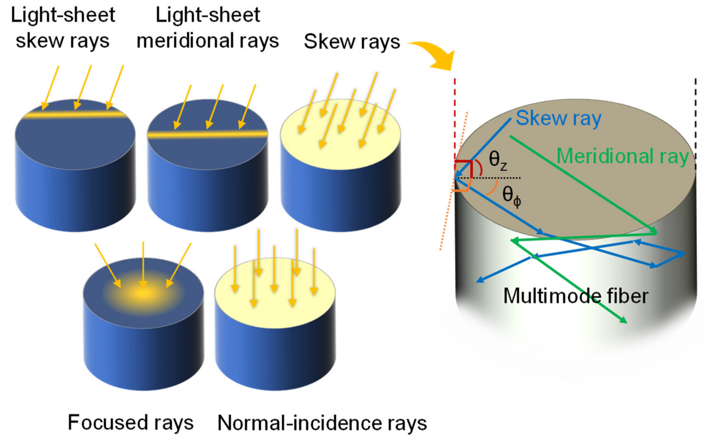
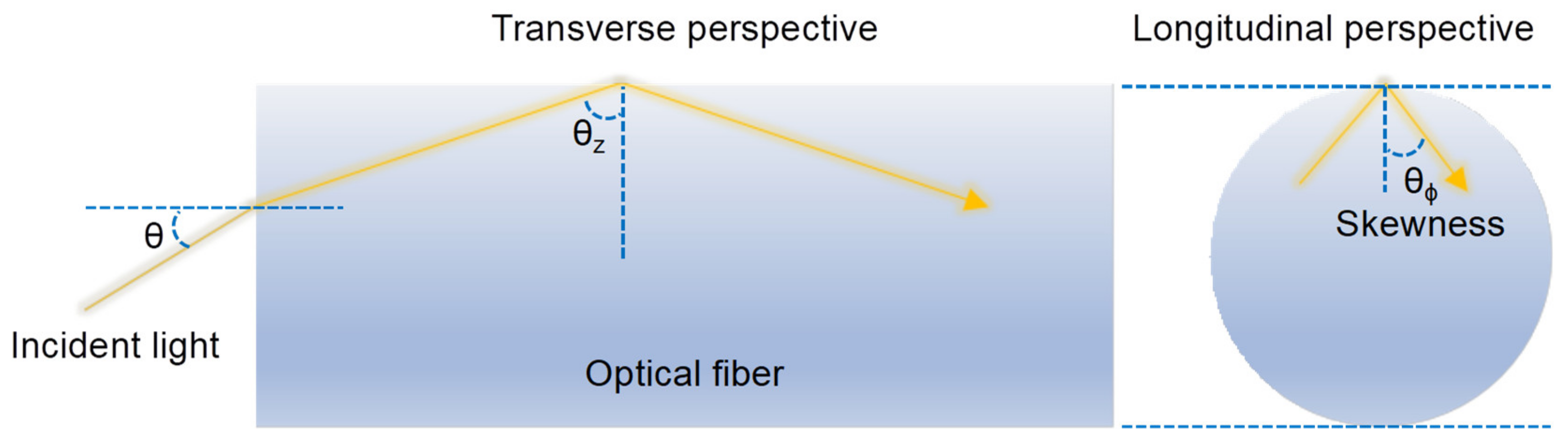
2.1. Definition
2.2. Relation to Modes
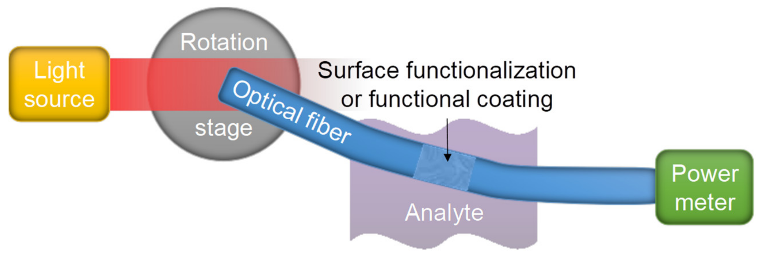
2.3. Practical Issues
2.4. Comparison to Other Sensor Designs
3. Theory
3.1. Angle Optimization
3.2. Ray Modeling
3.3. Ray Attenuation
3.4. Bend Loss
3.5. Mode Conversion Coefficients
3.6. Impulse Response of Fiber
3.7. Angular Momentum
3.8. Caustics
3.9. Speckle Field
3.10. Vortex Lens
4. Sensors Overview
4.1. Measurands
4.2. Sensor Optimization
4.3. Refractometers
4.4. Alkanes
4.5. Antigen
4.6. Relative Humidity
4.7. Aerosol
4.8. pH
4.9. Rhodamine
4.10. Light Source and Coupling
4.11. Fiber Defect
4.12. Weight
5. Discussions
5.1. Key Results
5.2. Challenges
5.3. Benefits
5.4. Future Development
6. Conclusions
Author Contributions
Funding
Acknowledgments
Conflicts of Interest
References
- Fabian, N.S.; Socorro, A.; Del Villar, I.; Diaz, S.; Matias, I.R.; Socorro, A. Multimode-Coreless-Multimode Fiber-Based Sensors: Theoretical and Experimental Study. J. Light. Technol. 2019, 37, 3844–3850. [Google Scholar] [CrossRef]
- Han, F.; Lang, T.; Mao, B.; Zhao, C.-L.; Kang, J.; Shen, C.; Wang, N. Surface plasmon resonance sensor based on coreless fiber for high sensitivity. Opt. Fiber Technol. 2019, 50, 172–176. [Google Scholar] [CrossRef]
- Xiong, Y.; Tan, J.; Wang, C.; Wu, J.; Wang, Q.; Chen, J.; Fang, S.; Duan, M. A miniaturized evanescent-wave free chlorine sensor based on colorimetric determination by integrating on optical fiber surface. Sens. Actuators B Chem. 2017, 245, 674–682. [Google Scholar] [CrossRef]
- Chevalier, P.; Piccardo, M.; De Naurois, G.-M.; Gabay, I.; Katzir, A.; Capasso, F. In-water fiber-optic evanescent wave sensing with quantum cascade lasers. Sens. Actuators B Chem. 2018, 262, 195–199. [Google Scholar] [CrossRef] [Green Version]
- Lou, J.; Wang, Y.; Tong, L. Microfiber Optical Sensors: A Review. Sensors 2014, 14, 5823–5844. [Google Scholar] [CrossRef] [Green Version]
- Prabowo, B.A.; Purwidyantri, A.; Liu, K.-C. Surface Plasmon Resonance Optical Sensor: A Review on Light Source Technology. Biosensors 2018, 8, 80. [Google Scholar] [CrossRef] [Green Version]
- Güemes, A.; Messervey, T.B. Smart textile and polymer fibers for structural health monitoring. Text. Polym. Compos. Build. 2010, 330–350. [Google Scholar] [CrossRef]
- Díaz, C.A.R.; Leal, A., Jr.; Frizera, A.; Pontes, M.J.; Antunes, P.F.C.; André, P.S.B.; Ribeiro, M.R.N. Temperature Cross-sensitivity Compensation in Liquid Level Sensor Using Mach-Zehnder Interferometers. In Proceedings Volume 10914, Optical Components and Materials XVI; SPIE: Bellingham, DC, USA, 2019. [Google Scholar]
- O’Toole, M.; Diamond, D. Absorbance Based Light Emitting Diode Optical Sensors and Sensing Devices. Sensors 2008, 8, 2453–2479. [Google Scholar] [CrossRef] [Green Version]
- Köhring, M.; Böttger, S.; Willer, U.; Schade, W. LED-Absorption-QEPAS Sensor for Biogas Plants. Sensors 2015, 15, 12092–12102. [Google Scholar] [CrossRef]
- Venkataraj, R.; Nampoori, V.P.N.; Radhakrishnan, P.; Kailasnath, M. Chemically Tapered Multimode Optical Fiber Probe for Fluoride Detection Based on Fluorescence Quenching of Curcumin. IEEE Sens. J. 2015, 15, 5584–5591. [Google Scholar] [CrossRef]
- Messica, A.; Greenstein, A.; Katzir, A. Theory of fiber-optic, evanescent-wave spectroscopy and sensors. Appl. Opt. 1996, 35, 2274–2284. [Google Scholar] [CrossRef] [PubMed]
- Wang, R.; Xiang, Y.; Zhou, X.; Liu, L.-H.; Shi, H.-C. A reusable aptamer-based evanescent wave all-fiber biosensor for highly sensitive detection of Ochratoxin A. Biosens. Bioelectron. 2015, 66, 11–18. [Google Scholar] [CrossRef] [PubMed]
- Snyder, A.; Mitchell, D.J. Leaky rays on circular optical fibers. J. Opt. Soc. Am. 1974, 64, 599. [Google Scholar] [CrossRef]
- Chen, G.G.; Shahnia, S.; Monro, T.M.; Lancaster, D. Force Sensors Using the Skew-Ray-Probed Plastic Optical Fibers. IEEE Photon. J. 2018, 10, 1–8. [Google Scholar] [CrossRef]
- Keating, M.P. Geometrical, Physical, and visual optics. Optom. Vis. Sci. 1988, 65, 989–990. [Google Scholar] [CrossRef]
- Torres, J.P.; Torner, L. Twisted Photons: Applications of light with Orbital Angular Momentum; Wiley-VCH: New York, NY, USA.
- Ma, C.; Ren, L.-Y.; Xu, Y.-P.; Wang, Y.-L.; Liang, J.; Qu, E.-S. Design and fabrication of tapered microfiber waveguide with good optical and mechanical performance. J. Mod. Opt. 2014, 61, 683–687. [Google Scholar] [CrossRef]
- Ooms, M.D.; Sieben, V.J.; Pierobon, S.C.; Jung, E.E.; Kalontarov, M.; Erickson, D.; Sinton, D. Evanescent photosynthesis: Exciting cyanobacteria in a surface-confined light field. Phys. Chem. Chem. Phys. 2012, 14, 4817. [Google Scholar] [CrossRef]
- Zhou, J.; Liao, C.; Wang, Y.; Yin, G.; Zhong, X.; Yang, K.; Sun, B.; Wang, G.; Li, Z. Simultaneous measurement of strain and temperature by employing fiber Mach-Zehnder interferometer. Opt. Express 2014, 22, 1680–1686. [Google Scholar] [CrossRef]
- Archenault, M.; Gagnaire, H.; Goure, J.P. A simple intrinsic optical fiber refractometer. Sens. Actuators B Chem. 1991, 5, 173–179. [Google Scholar] [CrossRef]
- Chen, G.G.; Monro, T.M.; Lancaster, D. Detection of microscopic defects in optical fiber coatings using angle-resolved skew rays. Opt. Lett. 2016, 41, 4036. [Google Scholar] [CrossRef]
- Love, J.D.; Midwinter, J.E.; Snyder, A. Report on The International Workshop on Optical Waveguide Theory, 21–23 September 1976, Lannion, France. Opt. Quantum Electron. 1977, 9, 84–86. [Google Scholar] [CrossRef]
- Potter, R.J.; Donati, E.; Tynan, R. Light-Collecting Properties of a Perfect Circular Optical Fiber. J. Opt. Soc. Am. 1963, 53, 256. [Google Scholar] [CrossRef]
- Potter, R.J. Transmission Properties of Optical Fibers. J. Opt. Soc. Am. 1961, 51, 1079. [Google Scholar] [CrossRef]
- Feuermann, D.; Gordon, J.M.; Huleihil, M. Light leakage in optical fibers: Experimental results, modeling and the consequences for solar concentrators. Sol. Energy 2002, 72, 195–204. [Google Scholar] [CrossRef]
- Chen, G.G.; Codemard, C.; Gorman, P.M.; Chan, J.S.; Zervas, M.N. Angle-Resolved Characterization and Ray-Optics Modeling of Fiber-Optic Sensors. J. Light. Technol. 2015, 33, 5210–5217. [Google Scholar] [CrossRef]
- Pike, J.N. Singly reflected skew rays inside a hollow tube: An exact cardiold solution for incident rim rays. Appl. Opt. 1991, 30, 3246. [Google Scholar] [CrossRef]
- Su, D.; Boechat, A.A.P.; Jones, J.D.C. Beam delivery by large-core fibers: Effect of launching conditions on near-field output profile. Appl. Opt. 1992, 31, 5816. [Google Scholar] [CrossRef]
- Zubia, J.; Aldabaldetreku, G.; Durana, G.; Arrue, J.; Jimenez, F. Light propagation in multi-step index optical fibers. Laser Photonics Rev. 2008, 2, 182–202. [Google Scholar] [CrossRef]
- Allington-Smith, J.; Dunlop, C.; Lemke, U.; Murray, G. End effects in optical fibers. Mon. Not. R. Astron. Soc. 2013, 436, 3492–3499. [Google Scholar] [CrossRef] [Green Version]
- Weiss, J.D. Trapping efficiency of fluorescent optical fibers. Opt. Eng. 2015, 54, 27101. [Google Scholar] [CrossRef] [Green Version]
- Chen, G.G.; Codemard, C.; Zervas, M.N.; Monro, T.M.; Lancaster, D. Enhanced pump absorption of active fiber components with skew rays. J. Light. Technol. 2016, 34, 1. [Google Scholar] [CrossRef]
- Pask, C.; Snyder, A.W. Multimode optical fibers: Interplay of absorption and radiation losses. Appl. Opt. 1976, 15, 1295. [Google Scholar] [CrossRef] [PubMed]
- Di Vita, P.; Vannucci, R. Loss mechanisms of leaky skew rays in optical fibers. Opt. Quantum Electron. 1977, 9, 177–188. [Google Scholar] [CrossRef]
- Dugas, J.; Sotom, M.; Martin, L.; Cariou, J.-M. Accurate characterization of the transmittivity of large-diameter multimode optical fibers. Appl. Opt. 1987, 26, 4198. [Google Scholar] [CrossRef] [PubMed]
- Kovačević, M.; Nikezic, D. Influence of bending on power distribution in step-index plastic optical fibers and the calculation of bending loss. Appl. Opt. 2006, 45, 6675–6681. [Google Scholar] [CrossRef]
- Åslund, M.; Jackson, S.D.; Canning, J.; Teixeira, A.; Lyytikäinen-Digweed, K. The influence of skew rays on angular losses in air-clad fibers. Opt. Commun. 2006, 262, 77–81. [Google Scholar] [CrossRef]
- Achenbach, C.P.; Cobb, J.H. Computational studies of light acceptance and propagation in straight and curved multimodal active fibers. J. Opt. A Pure Appl. Opt. 2003, 5, 239–249. [Google Scholar] [CrossRef] [Green Version]
- Ang, A.; Sugon, Q.M.; McNamara, D. Skew ray tracing in a step-index optical fiber using geometric algebra. Appl. Opt. 2015, 54, 3764. [Google Scholar] [CrossRef] [Green Version]
- Gambling, W.A.; Payne, D.N.; Matsumura, H. Mode conversion coefficients in optical fibers. Appl. Opt. 1975, 14, 1538–1542. [Google Scholar] [CrossRef]
- Cozannet, A.; Tréheux, M. Skew rays in optical fibers. Appl. Opt. 1975, 14, 1345. [Google Scholar] [CrossRef]
- Barrell, K.F.; Pask, C. Optical Fiber Excitation by Lenses. Opt. Acta. 1979, 26, 91–108. [Google Scholar] [CrossRef]
- Hashimoto, M. Circularly polarized modal skew rays in graded-index optical fibers. J. Opt. Soc. Am. 1982, 72, 1147–1151. [Google Scholar] [CrossRef]
- Herskowitz, G.; Kobrinski, H.; Levy, U. Optical power distribution in multimode fibers with angular-dependent mode coupling. J. Light. Technol. 1983, 1, 548–554. [Google Scholar] [CrossRef]
- Adler, C.L.; Lock, J.A.; Stone, B.R.; Garcia, C.J. High-order interior caustics produced in scattering of a diagonally incident plane wave by a circular cylinder. J. Opt. Soc. Am. A 1997, 14, 1305. [Google Scholar] [CrossRef] [Green Version]
- Bolshtyansky, M.A.; Savchenko, A.Y.; Zel’Dovich, B.Y. Use of skew rays in multimode fibers to generate speckle field with nonzero vorticity. Opt. Lett. 1999, 24, 433–435. [Google Scholar] [CrossRef] [PubMed]
- Johnson, E.; Stack, J.; Koehler, C. Light coupling by a vortex lens into graded index fiber. J. Light. Technol. 2001, 19, 753–758. [Google Scholar] [CrossRef]
- Benoit, V.; Yappert, M.C. Effect of Capillary Properties on the Sensitivity Enhancement in Capillary/Fiber Optical Sensors. Anal. Chem. 1996, 68, 183–188. [Google Scholar] [CrossRef]
- Gong, M.; Yuan, Y.; Li, C.; Yan, P.; Zhang, H.; Liao, S. Numerical modeling of transverse mode competition in strongly pumped multimode fiber lasers and amplifiers. Opt. Express 2007, 15, 3236–3246. [Google Scholar] [CrossRef]
- Ronot-Trioli, C.; Trouillet, A.; Veillas, C.; El-Shaikh, A.; Gagnaire, H. Fiber optic chemical sensor based on surface plasmon monochromatic excitation. Anal. Chim. Acta 1996, 319, 121–127. [Google Scholar] [CrossRef]
- Bin Lin, W.; Lacroix, M.; Chovelon, J.M.; Jaffrezic-Renault, N.; Gagnaire, H. Development of a fiber-optic sensor based on surface plasmon resonance on silver film for monitoring aqueous media. Sens. Actuators B Chem. 2001, 75, 203–209. [Google Scholar] [CrossRef]
- Dwivedi, Y.S.; Sharma, A.K.; Gupta, B.D. Influence of skew rays on the sensitivity and signal-to-noise ratio of a fiber-optic surface-plasmon-resonance sensor: A theoretical study. Appl. Opt. 2007, 46, 4563–4569. [Google Scholar] [CrossRef] [PubMed]
- Singh, S.; Verma, R.K.; Gupta, B.D. LED based fiber optic surface plasmon resonance sensor. Opt. Quantum Electron. 2010, 42, 15–28. [Google Scholar] [CrossRef]
- Cennamo, N.; Zeni, L.; Catalano, E.; Arcadio, F.; Minardo, A. Refractive Index Sensing through Surface Plasmon Resonance in Light-Diffusing Fibers. Appl. Sci. 2018, 8, 1172. [Google Scholar] [CrossRef] [Green Version]
- Chen, G.G.; Codemard, C.; Lewis, R.; Jankowski, Ł.; Chan, J.S.; Gorman, P.M.; Zervas, M.N. Enhanced responsivity with skew ray excitation of reflection- and transmission-type refractometric sensors. Opt. Lett. 2014, 39, 3822–3825. [Google Scholar] [CrossRef] [PubMed]
- Abdelghani, A.; Chovelon, J.M.; Jaffrezic-Renault, N.; Lacroix, M.; Gagnaire, H.; Veillas, C.; Berkova, B.; Chomat, M.; Matejec, V. Optical fiber sensor coated with porous silica layers for gas and chemical vapour detection. Sens. Actuators B Chem. 1997, 44, 495–498. [Google Scholar] [CrossRef]
- Bin Lin, W.; Jaffrezic-Renault, N.; Chovelon, J.M.; Lacroix, M. Optical fiber as a whole surface probe for chemical and biological applications. Sens. Actuators B Chem. 2001, 74, 207–211. [Google Scholar] [CrossRef]
- Srinivasan, K.L.; Khijwania, S.K.; Singh, J.P. Performance optimized optical fiber sensor for humidity measurement. Opt. Eng. 2005, 44, 034401. [Google Scholar] [CrossRef]
- Chen, G.G.; Wu, X.; Codemard, C.A.; Yu, L.; Liu, X.; Xu, H.; Monro, T.M.; Lancaster, D. Optical hygrometer using light-sheet skew-ray probed multimode fiber with polyelectrolyte coating. Sens. Actuators B Chem. 2019, 296, 126685. [Google Scholar] [CrossRef]
- Steinberg, I.; Kaplan, E.; Ben-David, M.; Gannot, I. The Role of Skew Rays in Biomedical Sensing. IEEE J. Sel. Top. Quantum Electron. 2009, 16, 961–966. [Google Scholar] [CrossRef]
- Hammarling, K.; Hilborn, J.; Nilsson, H.-E.; Manuilskiy, A. Blood pH optrode based on evanescent waves and refractive index change. In Proceedings of the SPIE Optical Fibers and Sensors for Medical Diagnostics and Treatment Applications XIV, San Francisco, CA, USA, 1–2 February 2014; p. 89381F-7. [Google Scholar]
- Chen, G.G.; Francois, A.; Wu, X.; Zhang, W.Q.; Codemard, C.; Xu, H.; Monro, T.M.; Lancaster, D. Light-Sheet Skew-Ray Enhanced Pump-Absorption for Sensing. J. Light. Technol. 2019, 37, 2140–2146. [Google Scholar] [CrossRef]
- Wang, J.; Chen, G.Y.; Wu, X.; Xu, H.; Monro, T.M.; Liu, T.; Lancaster, D.G. Light-Sheet Skew Ray-Enhanced Localized Surface Plasmon Resonance-Based Chemical Sensing. ACS Sens. 2019, 5, 127–132. [Google Scholar] [CrossRef] [PubMed]
- Klein, K.-F.; Gonschior, C.; Dahal, P.; Eckhardt, H.S.; Belz, M.; Hillrichs, G. Evanescent-field sensor using selectively excited modes in step-index fibers. In Proceedings of the Optical Fibers, Sensors, and Devices for Biomedical Diagnostics and Treatment XI, San Francisco, CA, USA, 22–27 January 2011. [Google Scholar] [CrossRef]
- Chen, G.G.; Otten, D.; Kang, Y.Q.; Monro, T.M.; Lancaster, D. Measuring the Radial Position of Defects within Optical Fibers Using Skew Rays. J. Sens. 2017, 2017, 1–5. [Google Scholar] [CrossRef]
- Ismaeel, R.; Lee, T.; Ding, M.; Belal, M.; Brambilla, G. Optical microfiber passive components. Laser Photon. Rev. 2012, 7, 350–384. [Google Scholar] [CrossRef] [Green Version]


| Excitation Type | Measured Attenuation (dB) | Repeatability (%) |
|---|---|---|
| Light-sheet skew rays (collimated) | 34.9 (20.0°, 12.5 µm) | ~5 |
| 32.0 (17.0°, 112.5 µm) | ||
| Meridional rays (collimated) | 30.2 (21.5°, 0 µm) | ~5 |
| Skew rays (collimated) | 21.2 (20.0°) | ~13 |
| 17.2 (15.5°) | ||
| Focused rays (tilted, centered) | ~19 higher than normal-incidence (1.7°) | N/A |
| Focused rays (centered) | 8.5 (1.7°) | ~3 |
| Normal-incidence rays | 0.9 (0°) | ~13 |
© 2020 by the authors. Licensee MDPI, Basel, Switzerland. This article is an open access article distributed under the terms and conditions of the Creative Commons Attribution (CC BY) license (http://creativecommons.org/licenses/by/4.0/).
Share and Cite
Chen, G.Y.; Wang, J.; Lancaster, D.G. Fiber-Optic Skew Ray Sensors. Sensors 2020, 20, 2499. https://doi.org/10.3390/s20092499
Chen GY, Wang J, Lancaster DG. Fiber-Optic Skew Ray Sensors. Sensors. 2020; 20(9):2499. https://doi.org/10.3390/s20092499
Chicago/Turabian StyleChen, George Y., Jinyu Wang, and David G. Lancaster. 2020. "Fiber-Optic Skew Ray Sensors" Sensors 20, no. 9: 2499. https://doi.org/10.3390/s20092499