1. Introduction
For tactical missiles, seeker (or detector) measurement and precision guidance are two key technologies, which would influence homing performance significantly. In practice, due to the seeker and filter dynamics, the complex information processing method and the target detection algorithm, significant seeker lags and delays always exist in the missile system. Consequently, the lags and delays may lead to the degradation of the guidance precision or even missing targets, as studied in [
1].
This problem motivates researchers to develop data compensation methods for the time-delay seeker. The general goal of these methods is to estimate the ideal measurement utilizing the undesirable output. Some researchers assumed the seeker dynamics model as a first-order lag system [
2,
3,
4,
5], and achieved adequate outcomes for many purposes. However, in many real situations, there exists both dynamics lags and pure time delays in the seeker system [
6,
7]. In the literatures considering this problem, the compensation or estimation approaches can be broadly divided into two directions:
Approaches based on a Kalman filter [
8,
9,
10,
11,
12];
Approaches based on a predictor observer [
13].
The former type of approach aims to obtain the estimation of time delays by fusing the system state variable and the measurement variable. Reference [
8] developed a Kalman filter insensitive to modeling errors to compensate one-sample delay in arrival of line-of-sight angle measurements. Additionally, [
9,
10], also based on Kalman filters, proposed feedback structures to model and estimate the delayed and lost measurements in the guidance systems, employing command to line-of-sight strategy. In [
11], a seeker time-delay model and a filter for obtaining the look angle rate in the feedback signal loop, based on the concept of the model matching technique, were introduced. Similarly, [
12] suggested a novel Kalman filter dynamic for time-delayed and noisy measurements of optical sensors, and analyzed the robustness of the delayed pointing error measurements. In general, these approaches build simple feedback loops and utilize filters to estimate the delayed state variables. However, these methods require an accurate delayed seeker model or target engagement model, which are always inaccurate in practice. Consequently, these approaches might have poor effectiveness and robustness under the uncertain situations.
For the second strategy, in [
13], a classical predictor observer was introduced, which had considerable engineering significance for linear time-delayed seeker systems. The proposed predictor observer consists of two components: a classical predictor feedback and a Luenberger observer. Though the proposed observer can also be implemented as a Kalman filter result from the identical structure, this approach was the first step in studying the application of predictor feedback to a time-delay missile guidance system. However, there is also much room for improvement. The predictor observer still has a strong requirement for accurate system models, including exact seeker delays. Additionally, the structure of the predictor leads to a conflict between increasing tracking speed and improving disturbances rejection.
In the engineering domain, there are other advanced approaches addressing the time-delay problem. In [
14,
15], cascade observers were employed for output-feedback control under parametric uncertainties, disturbances, and arbitrary sensor delays. On the basis of a predictor and sliding mode control, [
16] proposed a sliding mode predictive control for linear uncertain systems with time delays. Reference [
17] utilized disturbance observers to design a prediction-based control for multi-area interconnected power systems with input time delays. In addition, many time-delay compensation control strategies implementing active disturbance rejection control (ADRC) have been studied [
18,
19,
20,
21,
22,
23]. References [
19,
20] proposed modified ADRC structures by adding a time-delay loop and reconstructing a Smith predictor, respectively. Combined with a Smith predictor, [
21] proposed a fast self-learning ADRC algorithm, while [
22] transferred the system into a two-degree-freedom feedback control structure and used an internal model control for the delayed processes. Moreover, [
23] developed a novel higher-order ADRC method with a selectable response smoothing degree based on integrator-plus-dead-time models, which give better results in time-delayed compensation than simpler solutions [
19,
20]. Overall, the predictive ADRC method has adequate performances and properties in addressing time-delay system and rejecting disturbances, and it shows strong robustness under uncertain system modelling. However, this approach has not been applied in the problem of tactical missile guidance with time-delay seeker.
As for the development of guidance laws, sliding mode control (SMC) theory has been regarded as a powerful tool to design guidance laws with constraints. By constructing the sliding manifold with the first-order states (LOS angle) and second-order states (LOS angular rate), SMC method can reach global stabilization, where the sliding mode surface converges to zero [
24,
25]. In [
26], a nonsingular terminal sliding mode guidance law was implemented, which considered the impact angle constraint. Reference [
27] proposed an adaptive guidance law for obtaining a specified impact angle, and applied into a hypersonic vehicle. Adding a second-order sliding mode observer, [
28] proposed a robust guidance law with autopilot lag consideration. Reference [
29] presented an integral sliding mode guidance law which could resolve the steady-state error problem of the traditional SMC. An optimization design with the neural network was designed to improve the fuzzy variable structure of sliding mode in [
30]. However, the discontinuity of sliding mode controllers may cause an undesirable chattering of the system with fast actuators. Furthermore, the SMC guidance laws require certain target maneuvers, which are always unavailable in practice.
Thus, the adaptive super-twisting algorithm (STA) [
31] controller became popular due to its excellent property of eliminating chattering and disturbances. The main goal of adaptive controller design is to ensure a dynamical adaption of the control gains in order to be as small as possible while still sufficient to counteract the disturbances and ensure a sliding mode [
32,
33,
34]. In [
35], an adaptive STA guidance law which could converge in finite time was designed based on the increasing STA gains, as proposed in [
32]. There is a distinct disadvantage in that the gain will not decrease; as a consequence, the controller will not follow the disturbance when it is decreasing. To address this problem, reference [
36] utilized an equivalent control strategy, as proposed in [
33], and designed a STA-like guidance law with actuator faults constraint. Considering the target maneuvering as system disturbance, the guidance laws based on STA control have a smooth output without obtaining target maneuvering. However, due to the linear error form between the adaptive gain and the disturbance [
33,
36], the convergence speed of the error is slow and results in slow, even false, adaptive gains.
Inspired by above works, this study proposes a measurement compensation method based on predictive ADRC for time-delay seeker and a three-dimensional adaptive guidance law based on SMC and adaptive STA control. The main contributions of this paper can be concluded as follows:
A predictive ADRC method is first introduced into the tactical missile system to compensate the seeker lags and delays, which can achieve satisfied results under the approximate delay assumption and noisy measurement;
In order to design the sliding mode guidance law, a modified adaptive STA controller is applied to the tactical system to obtain adaptive gains with a faster convergence error form, and the stability of the control system is also analyzed.
The rest of the paper is organized as follows:
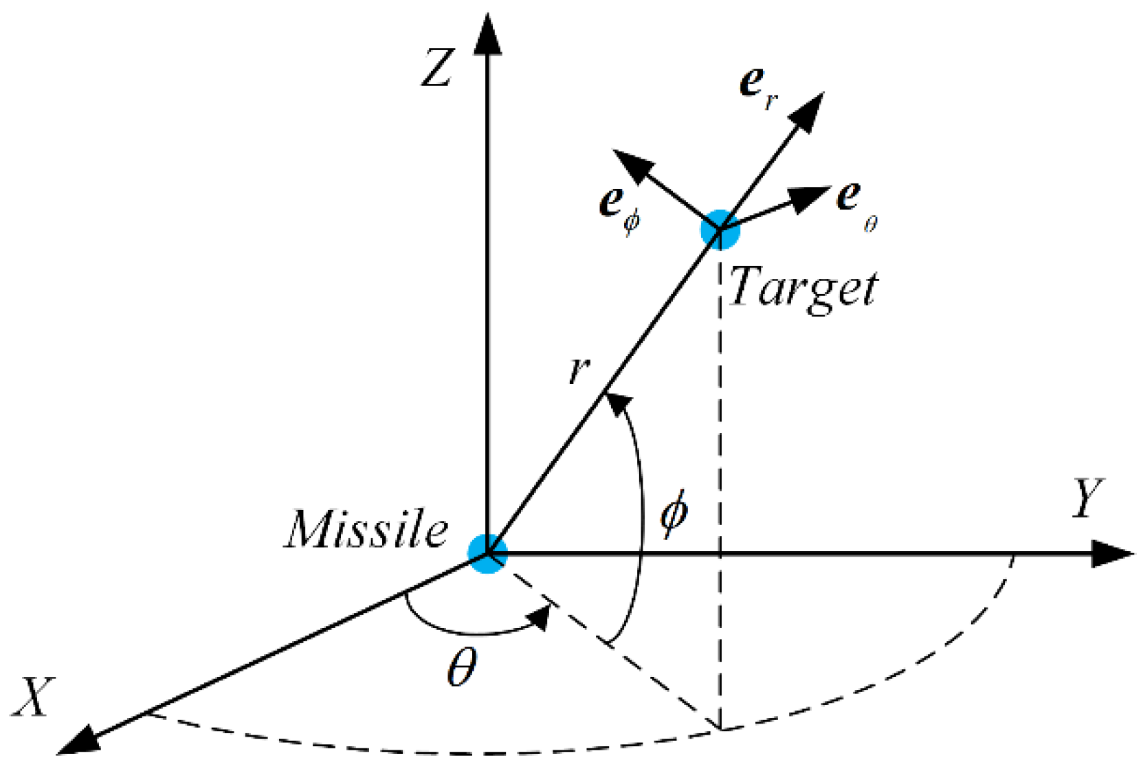
Section 2 states the missile-target engagement kinematics and preliminaries;
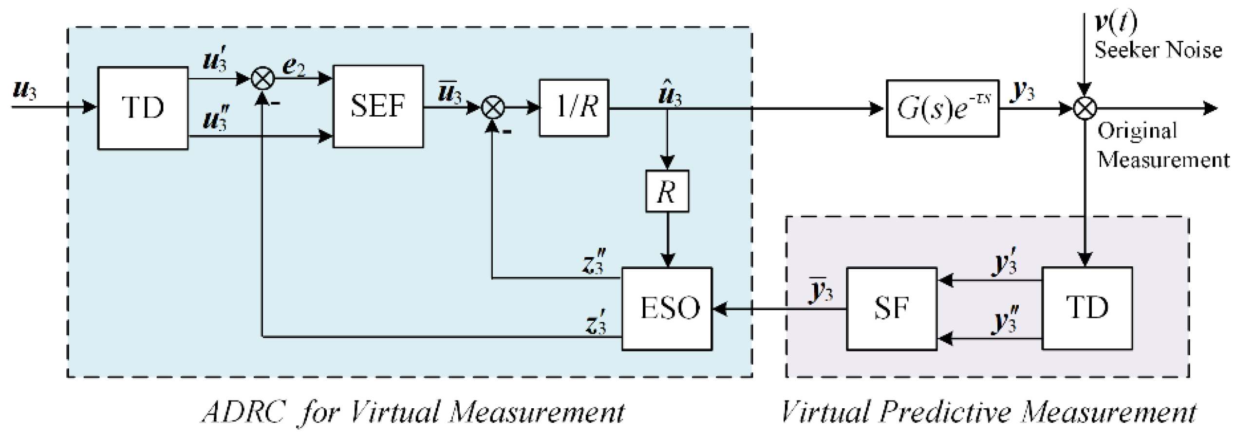
Section 3 builds a time-delay seeker measurement compensation system based on predictive ADRC;
Section 4 designs a sliding mode guidance law based on the compensation measurement and adaptive STA control;
Section 5 discusses the effectiveness of the proposed methods, utilizing several simulation examples.
5. Simulation
In this section, several simulation situations are designed to study the effectiveness of the proposed measurement compensation system and guidance law. First, the effectiveness of the compensation system based on predictive ADRC is discussed; next, variable desired terminal angles are taken in consideration to test the performance of the proposed guidance law with the compensation system. Finally, compared with other guidance laws, the property of the proposed guidance law with measurement compensation system is demonstrated further. All the simulations are supported by MATLAB platform due to its adequate libraries and powerful matrix calculation ability. Throughout the simulations, a fourth-order Runge-Kutta solver with a fixed step size is used.
5.1. Simulation of The Predicrive ADRC Compensation System
A simulation example of missile-target engagement guidance is investigated to verify the effectiveness of the proposed predictive ADRC compensation system (Equations (15)–(23)). In addition, this example is simulated on the basis of the proposed guidance law (Equation (32)).
Since the capacity of actuator dynamics is limited in real practice, the maximum lateral acceleration
is limited as follows
This paper selects throughout the simulations.
To address the discontinuity problem of the sign function
sign(
x), a sigmoid function is utilized to replace it during the simulation, which is formulated as
The simulation example is set up as follows: (1) the initial missile-target engagement condition:
,
,
,
,
,
and
; (2) the target maneuver condition:
, and
; (3) the seeker parameters:
,
, output noise is zero-mean Gaussian white noise with power spectral density
, and its variance is 0.0001 °/s considering narrow band; (4) the parameters of measurement compensation system are given in
Table 1; (5) the parameters of sliding mode manifold and adaptive STA are given in
Table 2; and (6) the fixed step size of the fourth-order Runge-Kutta solver is 0.001 s.
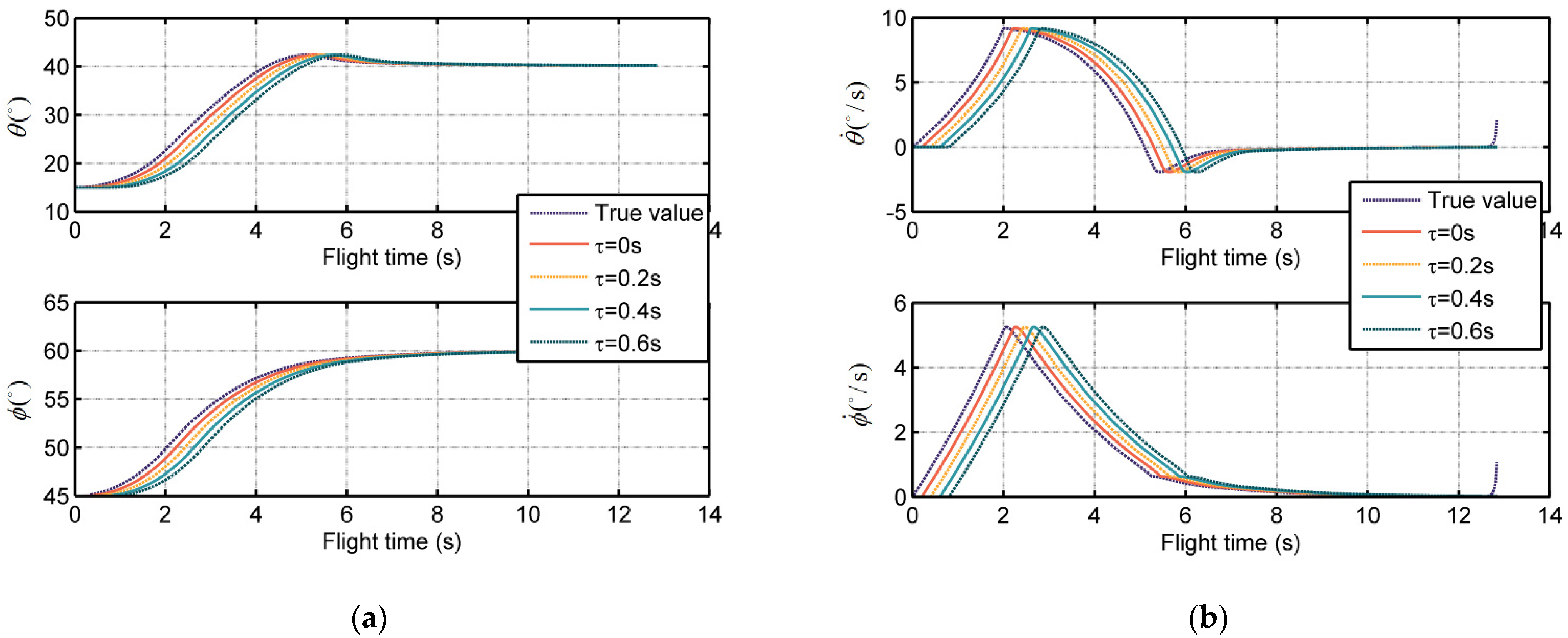
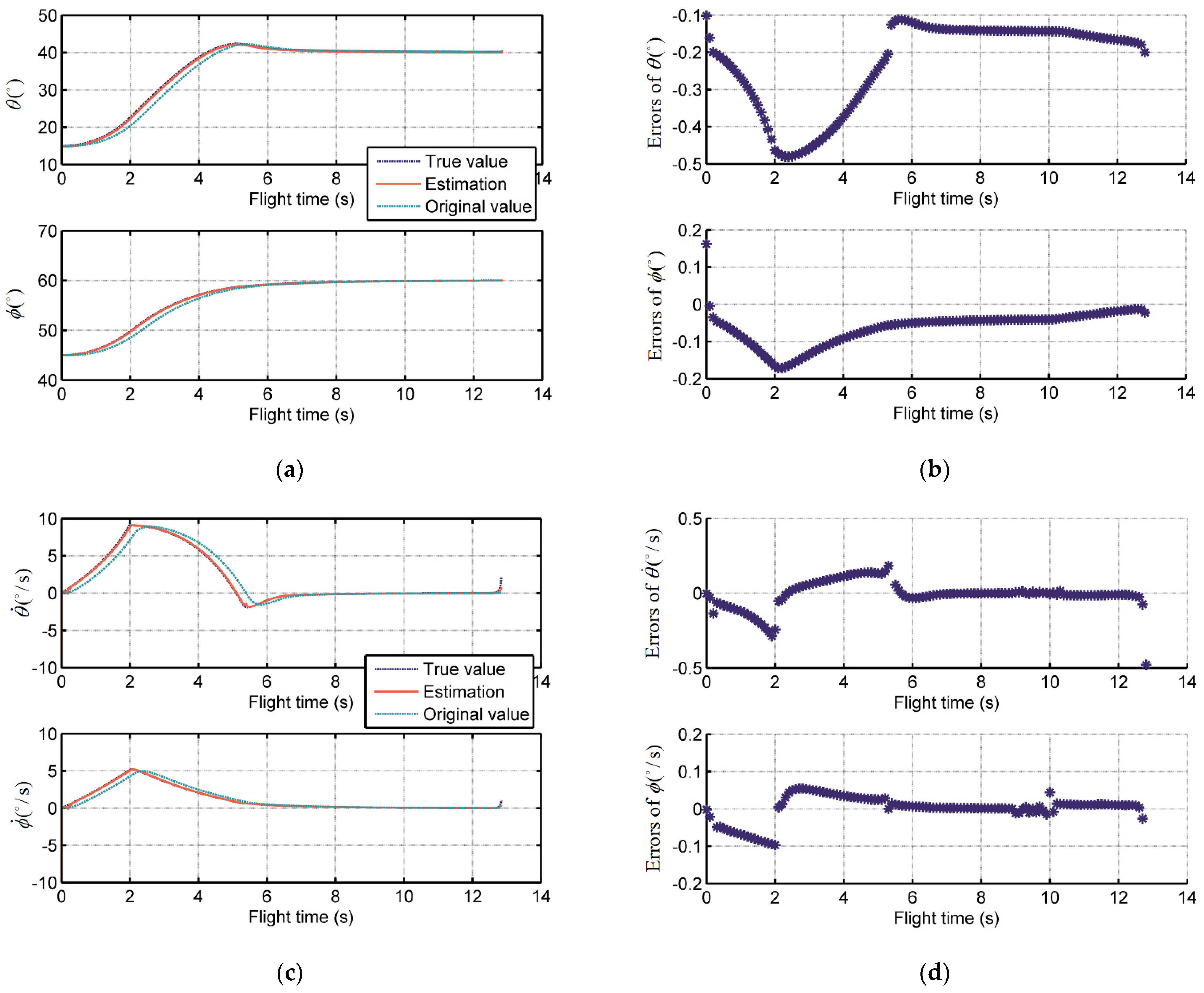
The simulation results are illustrated in
Figure 4.
Figure 4a,c show the LOS angle and LOS angular rate estimations of predictive ADRC compensation system, respectively. The estimation could track the true value calculated by the missile-target engagement dynamics in the overall guidance process. The original value detected by the time-delay seeker is also given as a comparison. Moreover, the errors between them are shown in
Figure 4b,d, which illustrates the good performance of the predictive ADRC compensation system quantitively. The error ranges of LOS angles
and
are (−0.5° to −0.1°) and (−0.2° to −0.2°), respectively, and that of LOS angular rates
and
are (−0.4 °/s to 0.2 °/s) and (−0.1 °/s to −0.1 °/s), respectively.
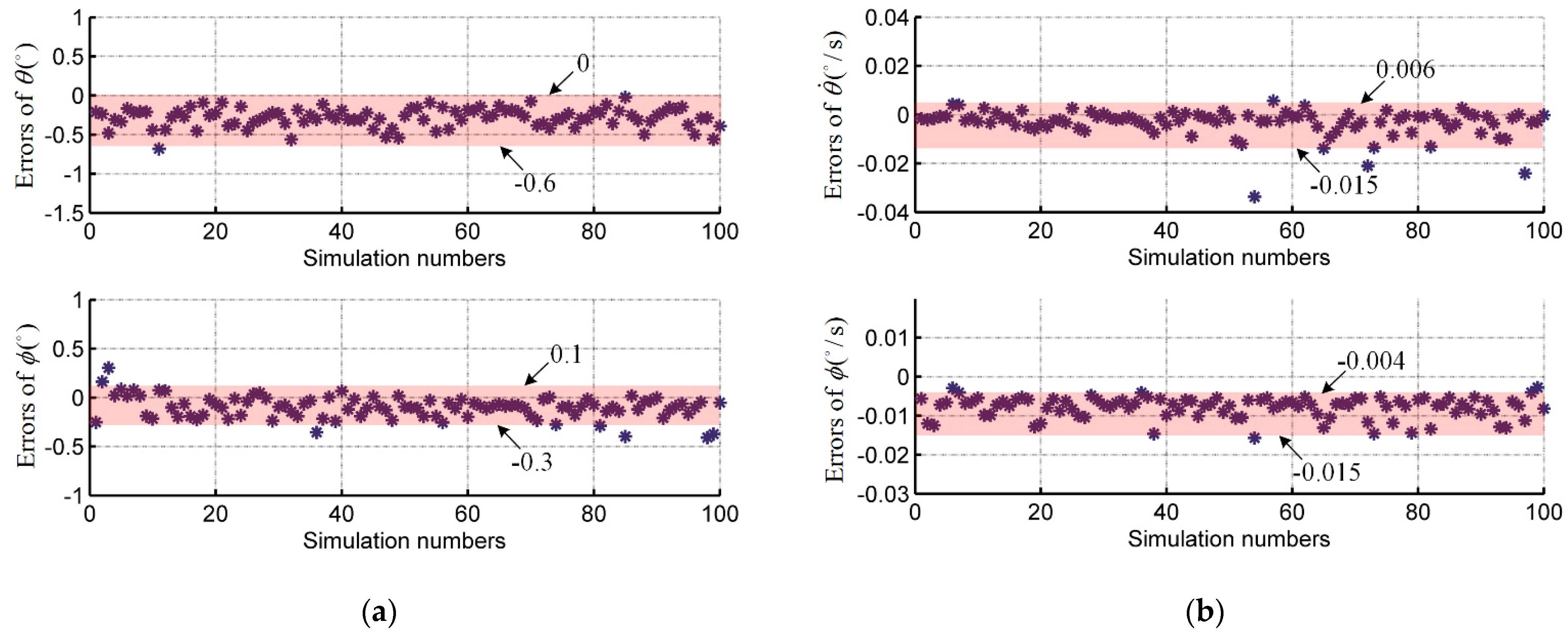
Figure 5 shows the Monte Carlo simulation result, where the single scatter point represents the average value of the errors between estimation values and true values during the entire flight time in one Monte Carlo run. Excluding a few large error scatters, the range of the error mean value can be governed. The mean value error ranges of LOS angles
and
are (−0.6° to 0°) and (−0.3° to 0.1°), respectively, and that of LOS angular rates
and
are (−0.015 °/s to 0.006 °/s) and (−0.015 °/s to −0.004 °/s), respectively. Those small errors demonstrate the strong property of robustness of the proposed predictive ADRC compensation system.
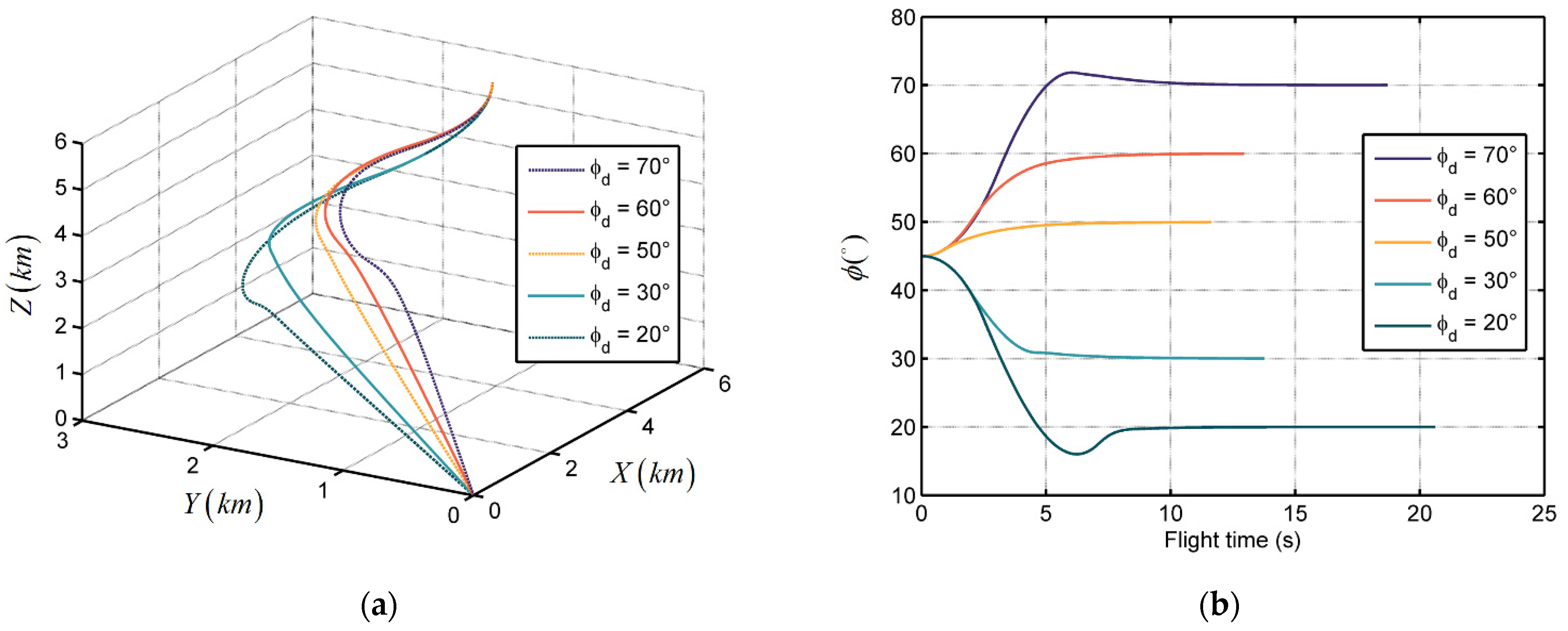
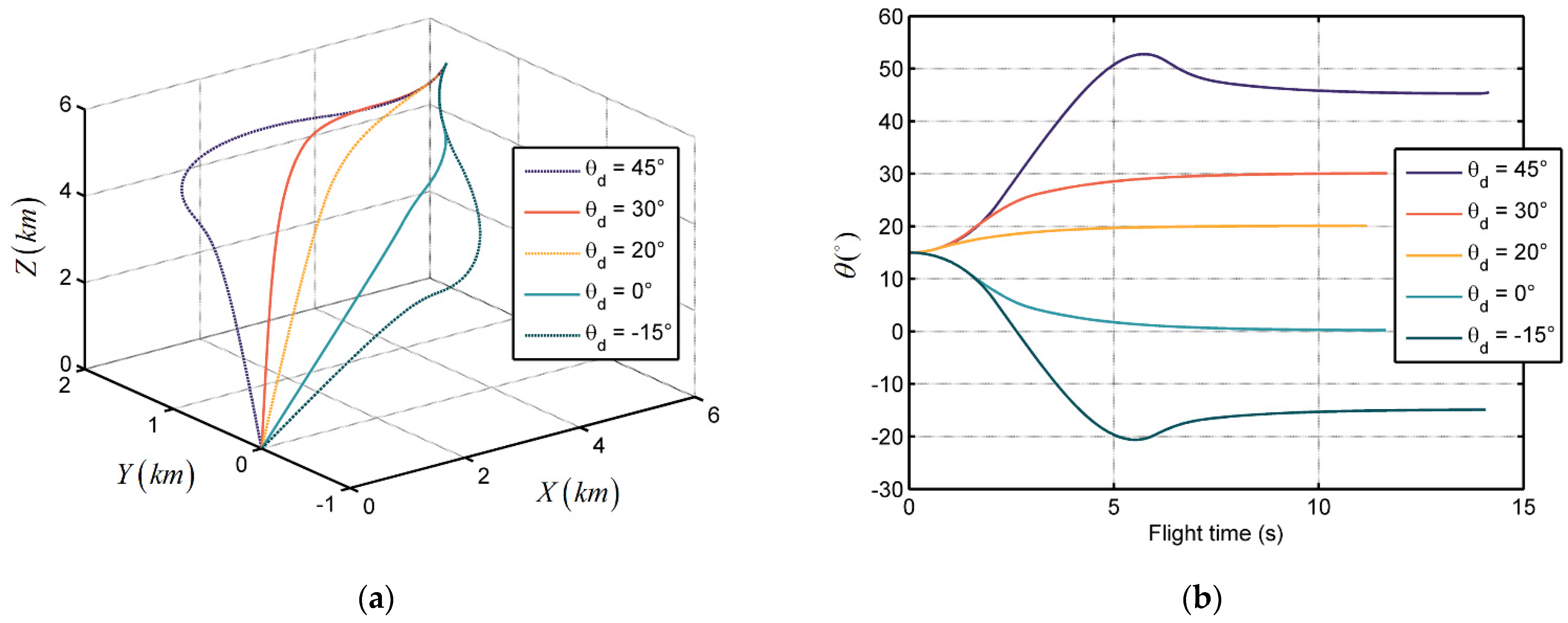
5.2. Simulation of Different Terminal Angle Constraints
In order to test the terminal angle constraint properties of the proposed guidance law with the ADRC predictor observer, a simulation example of missile-target engagement guidance is investigated. The missile is expected to hit the target in the desired terminal angles:
= 70°, 60°, 50°, 30°, and 20°, when
= 45°;
= 45°, 30°, 20°, 0°, and −15°, when
= 15°. Other initial conditions and system parameters are the same as in
Section 5.1.
The simulation results are illustrated in
Figure 6 and
Figure 7.
Figure 6a and
Figure 7a show the trajectories of missile target relative distances in the inertial coordinate system when
= 45° and
= 15°. We see that all the trajectories converge to zero, which implies that the missile can catch up with the target in finite time without obtaining target acceleration information.
Figure 6b and
Figure 7b show the trend of LOS angle over flight time in the two conditions. In this sample, the LOS angles
and
can reach the desired terminal angle within 7 s and 10 s, respectively, and then maintain it. This phenomenon verifies the terminal angle and seeker delay constraint properties of the proposed guidance law. Moreover, the convergence time and flight time are subject to the difference between the initial LOS angle and desired terminal angle. Larger gaps could lead to longer trajectories and longer convergence time.
5.3. Compared with Other Guidance Laws
The fixed-gain STA-based sliding mode control (STASMC) guidance law and fast convergent terminal sliding mode (TSM) guidance law are introduced for comparison. The fixed-gain STASMC guidance law is formulated as [
35]
This paper selects the parameters of (62) as , , , and .
The TSM guidance law is given by [
28]
This paper selects the parameters of (62) as , , and , and assumes the target acceleration is known for ease.
To further verify the applicability and robustness of the proposed guidance law and the proposed predictive ADRC compensation system, three kinds of scenarios with various measurement and target maneuvers are taken into account:
The seeker measurement is ideal, which has no delays or noises. The target accelerations in LOS coordinate is given by ;
The seeker measurement is ideal, which has no delays or noises. The target accelerations in LOS coordinate is given by ;
The seeker measurement has delays and noises, which are given by , , . The target accelerations in LOS coordinate is given by .
Besides the above, the initial conditions and parameters of these three scenarios are as same as that in
Section 5.1.
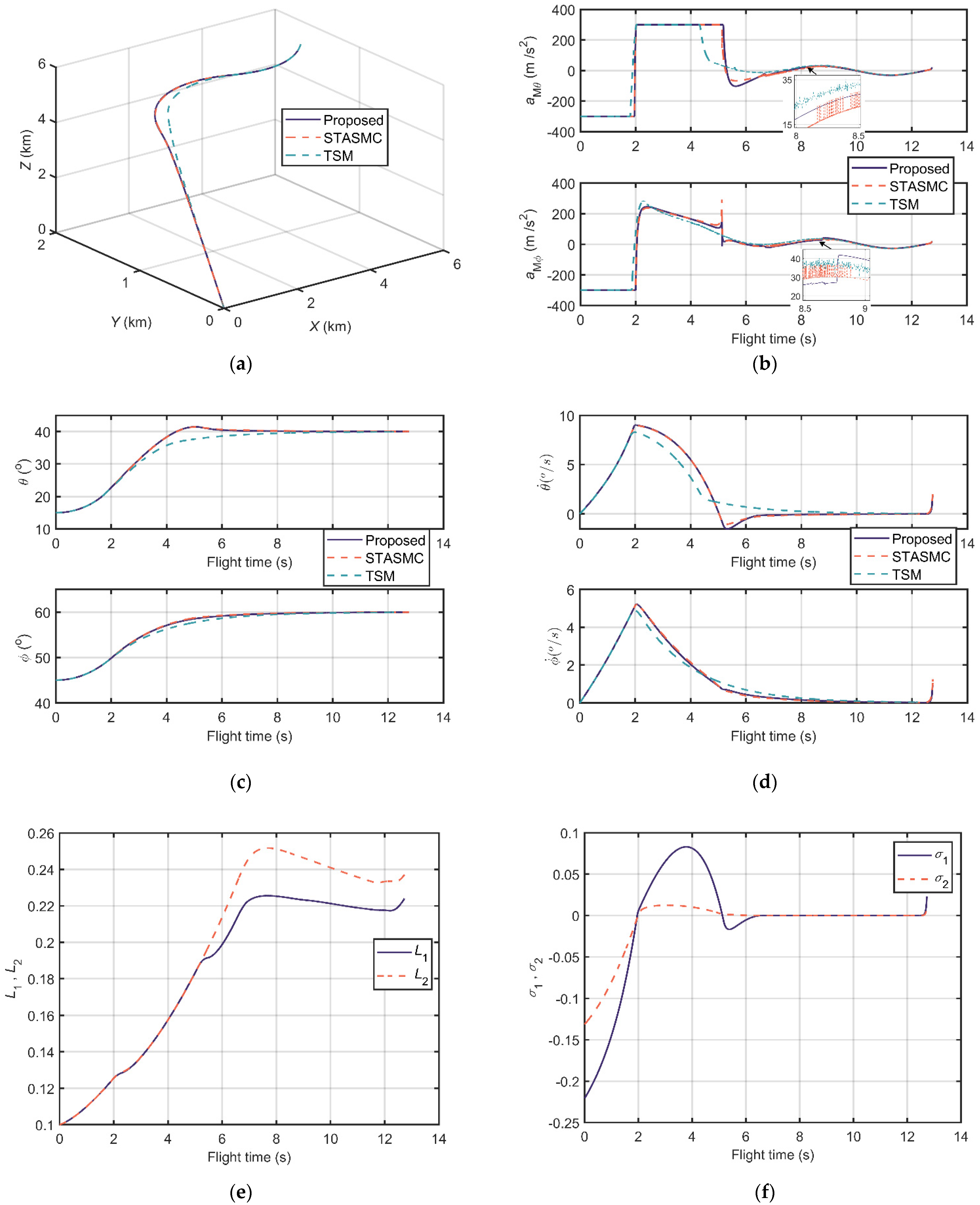
The comparison results of scenarios 1 and 2 are shown in
Figure 8 and
Figure 9, respectively.
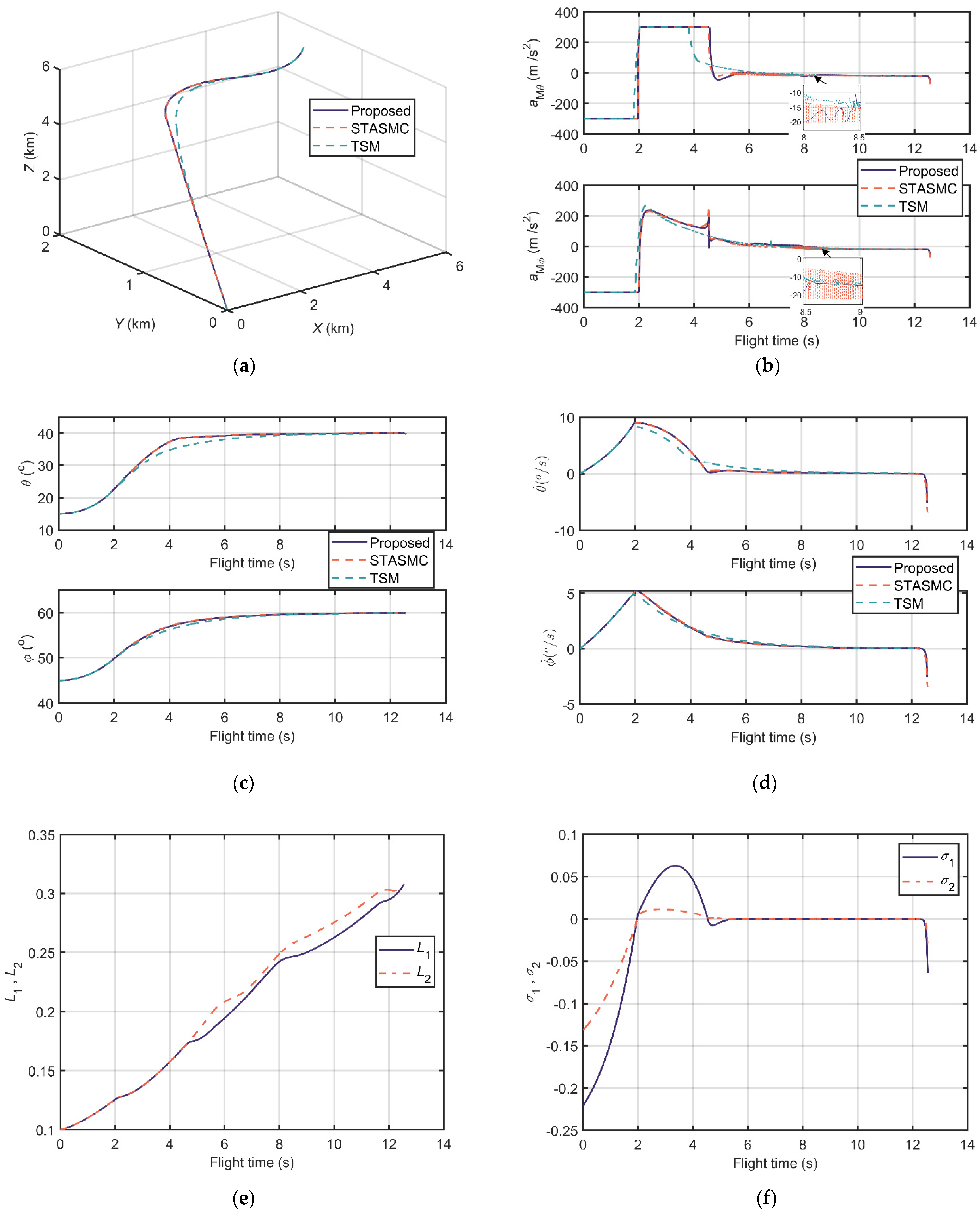
Figure 8a and
Figure 9a illustrate the relative distance trajectories, and all the three guidance laws converge to zero. In
Figure 8b and
Figure 9b, one can observe that the acceleration output of the proposed guidance law is continuous and smooth. Contrarily, the accelerations of STASMC and TSM chatter significantly. The LOS angle curves in
Figure 8c and
Figure 9c and the LOS angular rate curves in
Figure 8d and
Figure 9d depict the terminal angle constrained property of the guidance laws. The LOS angles of these three conditions can reach the desired terminal angle and the LOS angle rates can converge to zero.
Figure 8e and
Figure 9e show the trend of the adaptive STA gains of the proposed guidance law, which are bounded during flight time. The sliding variables of the proposed scenarios reach zero at approximately 6 s and 5 s, respectively, as shown in
Figure 8f and
Figure 9f.
Moreover, other information including flight time, miss distance, settling time (±0.5°), and error of LOS angles is listed in
Table 3 and
Table 4. Miss distance states the distance between missile and target at the end. Settling time (±0.5°) indicates the time that LOS angles reach the ±0.5° neighborhood of the desired terminal angles and then maintain it. Error of
θ and error of
ϕ are errors between simulation terminal angles and desired terminal angles. From
Table 3 and
Table 4, one can conclude that the proposed guidance law has a superior performance in miss distance, settling time (±0.5°), and terminal LOS angle errors in these two designed scenarios.
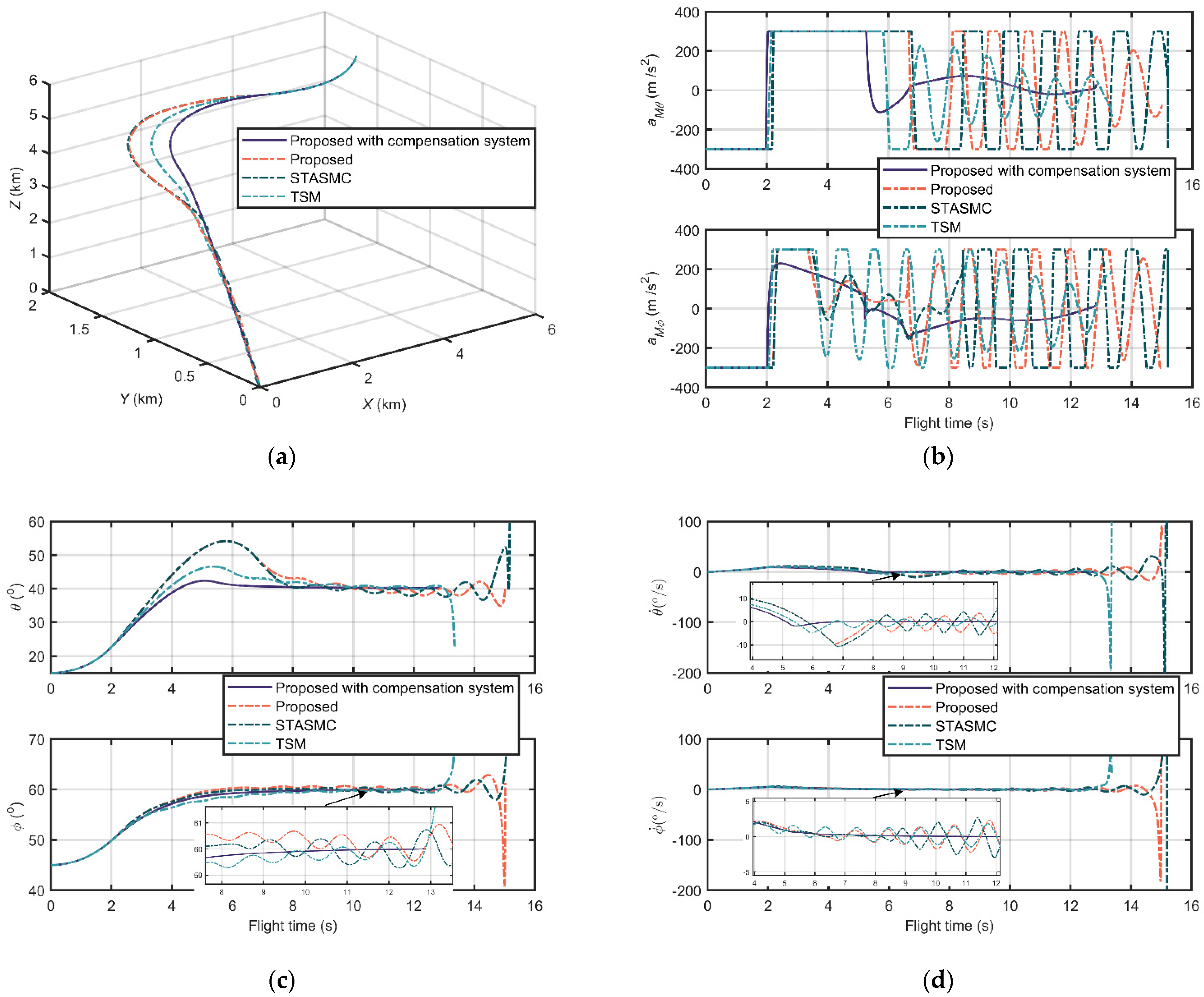
Unlike
Figure 8 and
Figure 9, the comparison results of scenario 3 in
Figure 10 take the proposed compensation system in account as well.
Figure 10a is the relative distance trajectories of the proposed guidance law with the proposed compensation system and the three guidance laws without measurement compensation structures. It is obvious that the trajectories of those without compensation have distinct chattering, and are longer than those proposed with a compensation system. The chattering also occurs in the aspects of output accelerations, LOS angles, and LOS angular rates, as shown in
Figure 10b,
Figure 10c and
Figure 10d, respectively. The chattering phenomenon is caused by the additional seeker lag, measurement delay, and noise. Due to this reason, the LOS angle and LOS angular rate curves of these three guidance laws do not converge. On the other hand, due to the compensation property of the proposed compensation system for lags, delays, and noises, the curves of the proposed guidance law with compensation system are smooth and stable in
Figure 10b–d.
Similarly, the information about flight time, miss distance, settling time (±0.5°), and LOS angle error is listed in
Table 5. We can observe that the proposed guidance law with compensation has the best performance in all aspects in this scenario. It should be noted that the settling time and LOS angle error of the proposed guidance law, STASMC, and TSM are not available due to their divergent LOS angles. Moreover, compared with the property of the proposed of scenario 1 listed in
Table 3, the proposed with compensation maintains broadly stable flight times and miss distances, but have a slightly decreasing performance in settling time and LOS angle error.
As a result, compared with STASMC and TSM, the proposed guidance law has no output chattering, less terminal LOS angle settling time, and error. In addition, the system which consists of the proposed guidance law and the proposed ADRC compensation structure has excellent seeker lag, delay, and noise constraint property and robustness.


