
Optical Wireless Link Operated at the Wavelength of 4.0 µm with Commercially Available Interband Cascade Laser


Abstract
1. Introduction
2. Materials and Methods
2.1. Calculations
2.2. Experiment
3. Results
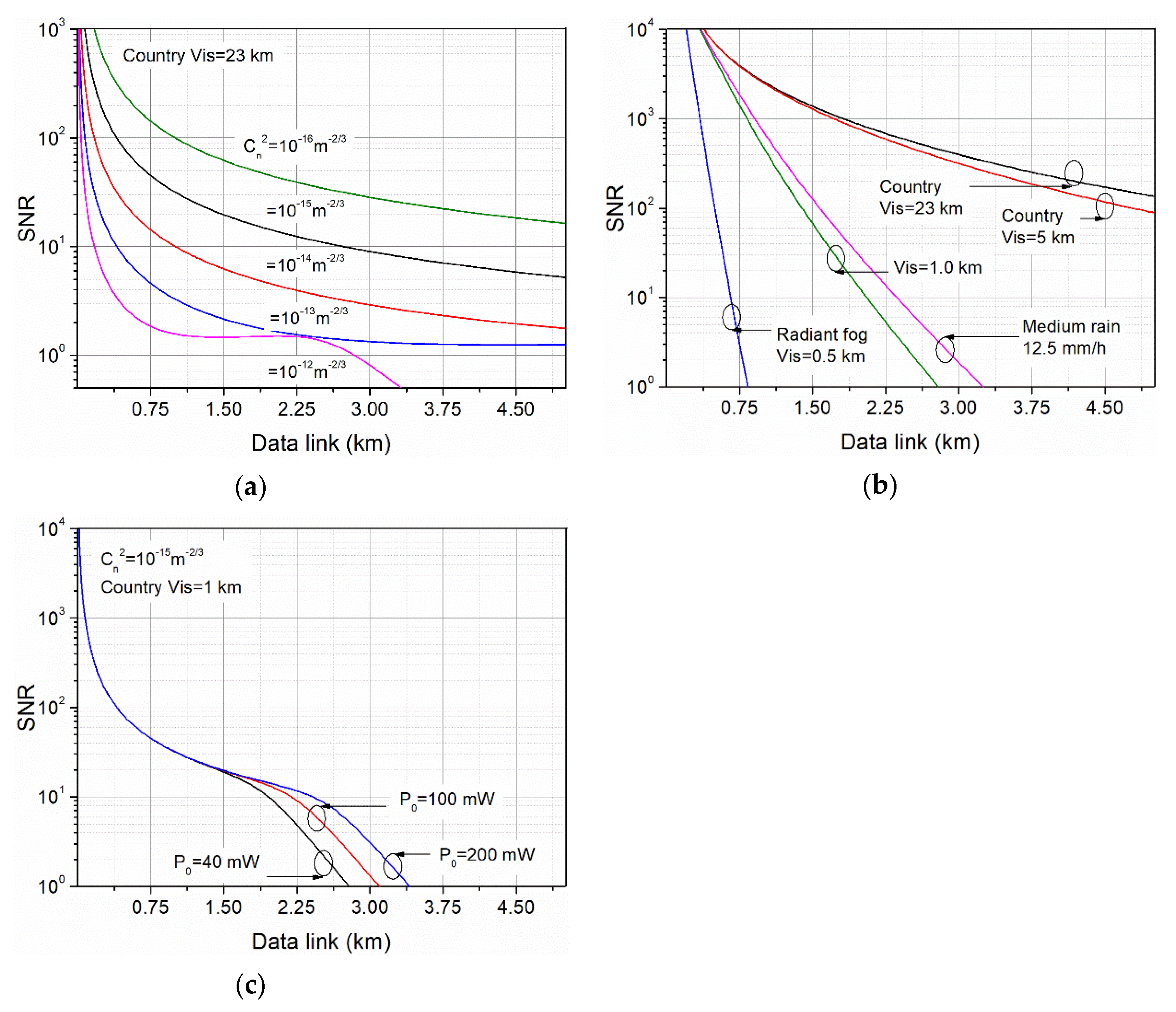
3.1. Calculations
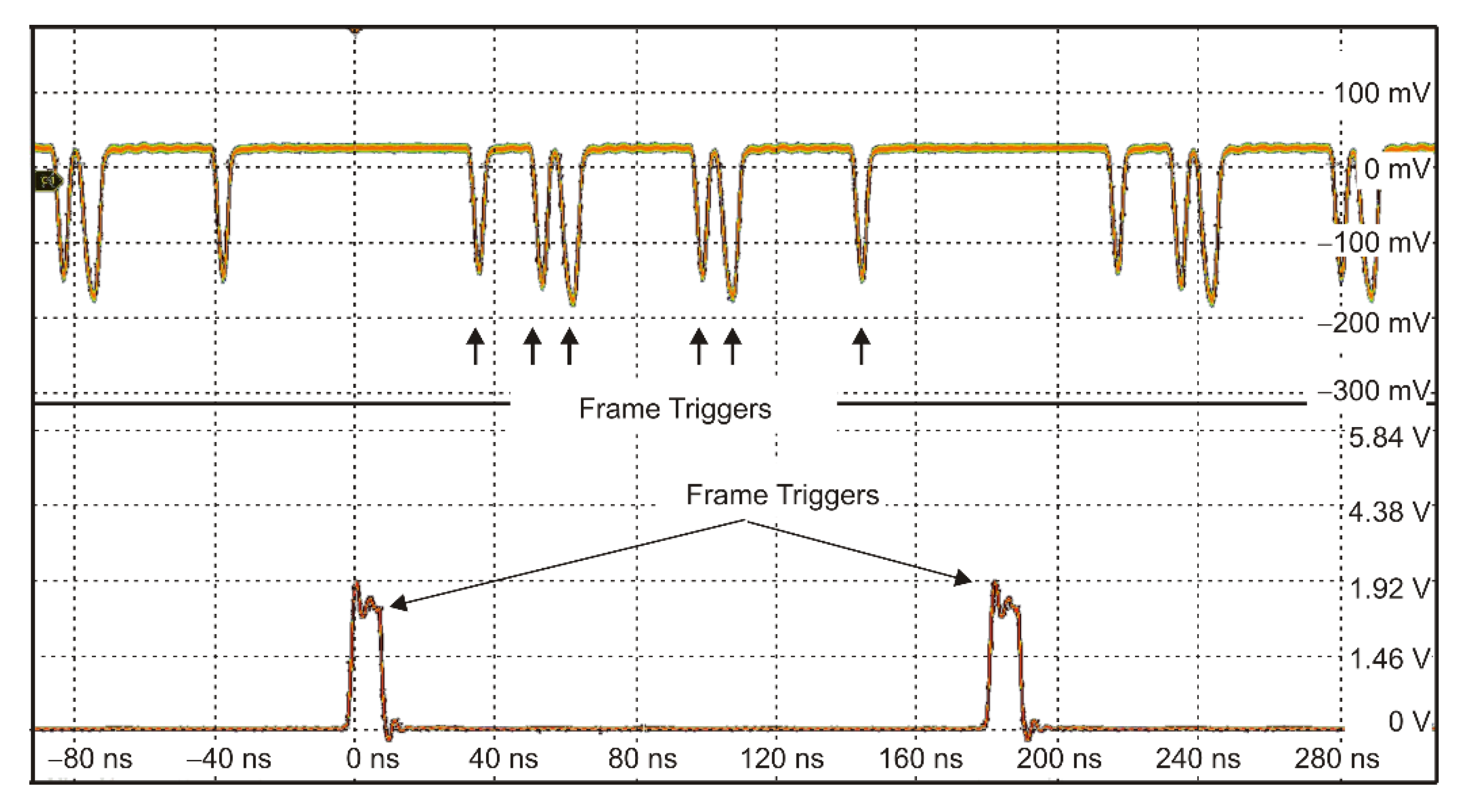
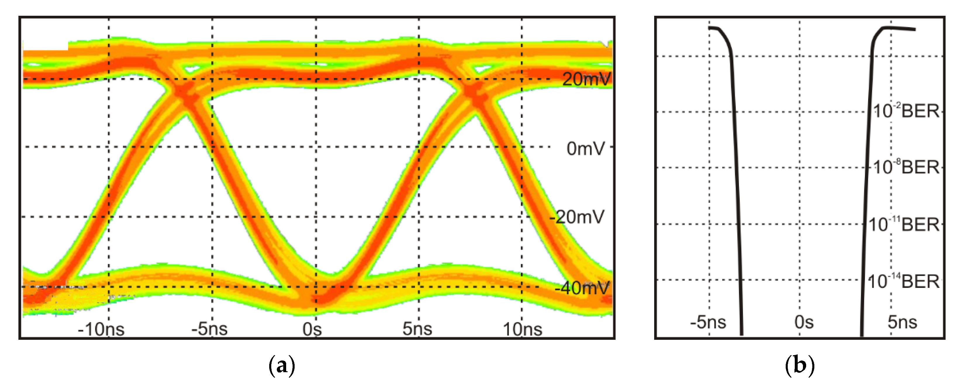
3.2. Experiment
4. Conclusions
Author Contributions
Funding
Institutional Review Board Statement
Informed Consent Statement
Data Availability Statement
Acknowledgments
Conflicts of Interest
References
- Schowengerdt, R.A. Remote Sensing: Models and Methods for Image Processing, 2nd ed.; Elsevier Science: Saint Louis, MO, USA, 2012; ISBN 978-008-051-610-3. [Google Scholar]
- Corrigan, P.; Martini, R.; Whittaker, E.A.; Bethea, C. Quantum cascade lasers and the Kruse model in free space optical communication. Opt. Express 2009, 17, 4355. [Google Scholar] [CrossRef] [PubMed]
- Zeller, J.; Manzur, T. Effect of atmosphere on free-space optical communication networks for border patrol. In Sensors, and Command, Control, Communications, and Intelligence (C3I) Technologies for Homeland Security and Homeland Defense IX; Carapezza, E.M., Ed.; International Society for Optics and Photonics: Bellingham, WA, USA, 2010; p. 766609. [Google Scholar]
- Soibel, A.; Wright, M.W.; Farr, W.H.; Keo, S.A.; Hill, C.J.; Yang, R.Q.; Liu, H.C. Midinfrared Interband Cascade Laser for Free Space Optical Communication. IEEE Photonics Technol. Lett. 2010, 22, 121–123. [Google Scholar] [CrossRef]
- Liu, C.; Zhai, S.; Zhang, J.; Zhou, Y.; Jia, Z.; Liu, F.; Wang, Z. Free-space communication based on quantum cascade laser. J. Semicond. 2015, 36, 94009. [Google Scholar] [CrossRef]
- Pang, X.; Ozolins, O.; Schatz, R.; Storck, J.; Udalcovs, A.; Navarro, J.R.; Kakkar, A.; Maisons, G.; Carras, M.; Jacobsen, G.; et al. Gigabit free-space multi-level signal transmission with a mid-infrared quantum cascade laser operating at room temperature. Opt. Lett. 2017, 42, 3646–3649. [Google Scholar] [CrossRef]
- Johnson, S.M.; Dial, E.; Razeghi, M. High-speed free space optical communications based on quantum cascade lasers and type-II superlattice detectors. Proc. SPIE 2020, 11288, 1128814. [Google Scholar] [CrossRef]
- Hao, Q.; Zhu, G.; Yang, S.; Yang, K.; Duan, T.; Xie, X.; Huang, K.; Zeng, H. Mid-infrared transmitter and receiver modules for free-space optical communication. Appl. Opt. 2017, 56, 2260–2264. [Google Scholar] [CrossRef] [PubMed]
- Soibel, A.; Wright, M.; Farr, W.; Keo, S.; Hill, C.; Yang, R.Q.; Liu, H.C. Free space optical communication utilizing mid-infrared interband cascade laser. Proc. SPIE 2010, 7587, 75870S. [Google Scholar] [CrossRef]
- Pang, X.; Ozolins, O.; Zhang, L.; Schatz, R.; Udalcovs, A.; Yu, X.; Jacobsen, G.; Popov, S.; Chen, J.; Lourdudoss, S. Free-Space Communications Enabled by Quantum Cascade Lasers. Phys. Status Solidi A 2021, 218, 20000407. [Google Scholar] [CrossRef]
- Vurgaftman, I.; Bewley, W.W.; Canedy, C.L.; Kim, C.S.; Kim, M.; Merritt, C.D.; Abell, J.; Lindle, J.R.; Meyer, J.R. Rebalancing of internally generated carriers for mid-infrared interband cascade lasers with very low power consumption. Nat. Commun. 2011, 2, 585. [Google Scholar] [CrossRef] [PubMed]
- Vurgaftman, I.; Weih, R.; Kamp, M.; Meyer, J.R.; Canedy, C.L.; Kim, C.S.; Kim, M.; Bewley, W.W.; Merritt, C.D.; Abell, J.; et al. Interband cascade lasers. J. Phys. D Appl. Phys. 2015, 48, 123001. [Google Scholar] [CrossRef]
- Bauer, A.; Langer, F.; Dallner, M.; Kamp, M.; Motyka, M.; Sęk, G.; Ryczko, K.; Misiewicz, J.; Höfling, S.; Forchel, A. Emission wavelength tuning of interband cascade lasers in the 3–4 μm spectral range. Appl. Phys. Lett. 2009, 95, 251103. [Google Scholar] [CrossRef]
- Jiang, Y.; Li, L.; Tian, Z.; Ye, H.; Zhao, L.; Yang, R.Q.; Mishima, T.D.; Santos, M.B.; Johnson, M.B.; Mansour, K. Electrically widely tunable interband cascade lasers. J. Appl. Phys. 2014, 115, 113101. [Google Scholar] [CrossRef]
- Risby, T.H.; Tittel, F.K. Current status of midinfrared quantum and interband cascade lasers for clinical breath analysis. Opt. Eng. 2010, 49, 1–14. [Google Scholar] [CrossRef]
- Lundqvist, S.; Kluczynski, P.; Weih, R.; von Edlinger, M.; Nähle, L.; Fischer, M.; Bauer, A.; Höfling, S.; Koeth, J. Sensing of formaldehyde using a distributed feedback interband cascade laser emitting around 3493 nm. Appl. Opt. 2012, 51, 6009. [Google Scholar] [CrossRef]
- Stassinakis, A.N.; Papavgeris, G.A.; Nistazakis, H.E.; Tsigopoulos, A.D.; Androutsos, N.A.; Tombras, G.S. Experimental Model Development for the Attenuation Coefficient Estimation of Terrestrial Optical Wireless Links over the Sea. Telecom 2021, 2, 7. [Google Scholar] [CrossRef]
- Plank, T.; Leitgeb, E.; Pezzei, P.; Ghassemlooy, Z. Wavelength-selection for high data rate Free Space Optics (FSO) in next generation wireless communications. In Proceedings of the 2012 17th European Conference on Networks and Optical Communications, Vilanova i la Geltru, Spain, 20–22 June 2012; pp. 1–5. [Google Scholar]
- Chauhan, S.; Miglani, R.; Kansal, L.; Gaba, G.S.; Masud, M. Performance Analysis and Enhancement of Free Space Optical Links for Developing State-of-the-Art Smart City Framework. Photonics 2020, 7, 132. [Google Scholar] [CrossRef]
- Willebrand, H.; Ghuman, B. Free Space Optics: Enabling Optical Connectivity in Today’s Networks; Sams: Washington, DC, USA, 2001; ISBN 067232248X. [Google Scholar]
- ITUR. P.1817 Propagation Data Required for the Design of Terrestrial Free-Space Optical Links; ITU-Recommendation: Geneva, Switzerland, 2012. [Google Scholar]
- Kim, I.I.; McArthur, B.; Korevaar, E.J. Comparison of laser beam propagation at 785 nm and 1550 nm in fog and haze for optical wireless communications. Proc. SPIE 2001, 4214, 26–37. [Google Scholar] [CrossRef]
- Anthonisamy, A.B.R.; James, A.V.S. Formulation of atmospheric optical attenuation model in terms of weather data. J. Opt. 2016, 45, 120–135. [Google Scholar] [CrossRef]
- Nadeem, F.; Flecker, B.; Leitgeb, E.; Khan, M.S.; Awan, M.S.; Javornik, T. Comparing the fog effects on hybrid network using Optical Wireless and GHz links. In Proceedings of the 6th International Symposium Communication Systems, Networks and Digital Signal Processing, Graz, Austria, 25 July 2008; pp. 278–282. [Google Scholar] [CrossRef]
- Singh, H.; Chechi, D.P. Performance Evaluation of Free Space Optical (FSO) Communication Link: Effects of Rain, Snow and Fog. In Proceedings of the 6th International Conference on Signal Processing and Integrated Networks (SPIN), Noida, India, 7–8 March 2019; IEEE: Graz, Austria, 2019; pp. 387–390. [Google Scholar] [CrossRef]
- Zabidi, S.A.; Islam, M.R.; Khateeb, W.A.; Naji, A.W. Investigating of rain attenuation impact on Free Space Optics propagation in tropical region. In Proceedings of the 4th International Conference on Mechatronics: Integrated Engineering for Industrial and Societal Development, ICOM’11—Conference Proceedings, Kuala Lumpur, Malaysia, 17–19 May 2011; pp. 1–6. [Google Scholar] [CrossRef]
- Kaur, A.; Singh, M.L. Comparing the Effect of Fog and Snow Induced Attenuation on Free Space Optics (FSO) and RF Links. Int. J. Comput. Sci. Technol. 2012, 8491, 554–556. [Google Scholar]
- Esmail, M.A.; Fathallah, H.; Alouini, M.S. An Experimental Study of FSO Link Performance in Desert Environment. IEEE Commun. Lett. 2016, 20, 1888–1891. [Google Scholar] [CrossRef]
- Garlinska, M.; Pregowska, A.; Masztalerz, K.; Osial, M. From Mirrors to Free-Space Optical Communication—Historical Aspects in Data Transmission. Futur. Internet 2020, 12, 179. [Google Scholar] [CrossRef]
- Zhang, S.; Hu, Y.; Hao, Q. Advances of Sensitive Infrared Detectors with HgTe Colloidal Quantum Dots. Coatings 2020, 10, 760. [Google Scholar] [CrossRef]
- Downs, C.; Vandervelde, T. Progress in Infrared Photodetectors Since 2000. Sensors 2013, 13, 5054–5098. [Google Scholar] [CrossRef]
- Kalinowski, P.; Mikołajczyk, J.; Piotrowski, A.; Piotrowski, J. Recent advances in manufacturing of miniaturized uncooled IR detection modules. Semicond. Sci. Technol. 2019, 34, 033002. [Google Scholar] [CrossRef]
- Vitasek, J.; Latal, J.; Hejduk, S.; Bocheza, J.; Koudelka, P.; Skapa, J.; Siska, P.; Vasinek, V. Atmospheric turbulences in Free Space Optics channel. In Proceedings of the 2011 34th International Conference on Telecommunications and Signal Processing (TSP), Budapest, Hungary, 18–20 August 2011; pp. 104–107. [Google Scholar]
- Bai, F.; Su, Y.; Sato, T. Performance Analysis of Polarization Modulated Direct Detection Optical CDMA Systems over Turbulent FSO Links Modeled by the Gamma-Gamma Distribution. Photonics 2015, 2, 139–155. [Google Scholar] [CrossRef]
- Sahota, J.K.; Dhawan, D. Reducing the effect of scintillation in FSO system using coherent based homodyne detection. Optik 2018, 171, 20–26. [Google Scholar] [CrossRef]
- Prokes, A. Atmospheric effects on availability of free space optics systems. Opt. Eng. 2009, 48, 066001. [Google Scholar] [CrossRef]
- Wolfe, A.; Zissis, W.L. The Infrared Handbook; The Office: Washington, DC, USA, 1978; Volume PM02, ISBN 096035901X/9780960359011. [Google Scholar]
- Andrews, L.C. Field Guide to Atmospheric Optics, 2nd ed.; SPIE PRESS: Bellingham, WA, USA, 2009; Volume FG41, ISBN 978-151-0619-371. [Google Scholar]
- Lee, I.E.; Ghassemlooy, Z.; Ng, W.P.; Uysal, M. Performance analysis of free space optical links over turbulence and misalignment induced fading channels. In Proceedings of the 2012 8th International Symposium on Communication Systems, Networks & Digital Signal Processing (CSNDSP), Poznan, Poland, 18–20 July 2011; pp. 1–6. [Google Scholar] [CrossRef]


| Wavelength | Laser | Data Rate | Modulation * | Distance | Temperature | Year |
|---|---|---|---|---|---|---|
| 3.0 μm | ICL | 70 Mb/s | NRZ-OOK | 1 m | 77 K | 2009 [4] |
| 4.7 μm | QCL | 40 MHz | Analog | 2.5 m | 293 K | 2015 [5] |
| 4.65 μm | QCL | 3 Gb/s | NRZ-OOK, PAM-4, PAM-8 | 5 cm | 293 K | 2017 [6] |
| 4.65 μm | QCL | 4 Gb/s | PAM-4, DMT | cm | 293 K | 2017 [9] |
| 4.8 μm | QCL | 10 MHz | Analog | m | 293 K | 2020 [7] |
| 3.0 μm | ICL | 70 Mb/s | OOK | cm | 77 K | 2010 [8] |
| 4.0 μm | ICL | 70 Mb/s 155 Mb/s | NRZ-OOK RZ-OOK | 2 m | 298 K | This work |
| λ | Aerosol Model *, Vis [km] | ||||||||
|---|---|---|---|---|---|---|---|---|---|
| A | C 23 km | C 5 km | T 5 km | M 23 km | D 23 km | F 0.5 km | R 12.5 mm/h | H 2 mm/h | |
| 1.5 μm | 0.20 | 0.24 | 0.40 | 0.43 | 0.31 | 0.22 | 8.92 | 2.08 | 0.86 |
| 4.0 μm | 0.05 | 0.06 | 0.13 | 0.15 | 0.12 | 0.07 | 10.58 | 1.88 | 0.65 |
| Parameter | Value | Spectral Characteristics |
|---|---|---|
| Active area | 1 × 1 mm2 |  |
| Detector resistance | 60 kΩ | |
| Current noise density | 2.4 pA/√Hz | |
| Responsivity | 2.25 A/W |
Publisher’s Note: MDPI stays neutral with regard to jurisdictional claims in published maps and institutional affiliations. |
© 2021 by the authors. Licensee MDPI, Basel, Switzerland. This article is an open access article distributed under the terms and conditions of the Creative Commons Attribution (CC BY) license (https://creativecommons.org/licenses/by/4.0/).
Share and Cite
Mikołajczyk, J.; Weih, R.; Motyka, M. Optical Wireless Link Operated at the Wavelength of 4.0 µm with Commercially Available Interband Cascade Laser. Sensors 2021, 21, 4102. https://doi.org/10.3390/s21124102
Mikołajczyk J, Weih R, Motyka M. Optical Wireless Link Operated at the Wavelength of 4.0 µm with Commercially Available Interband Cascade Laser. Sensors. 2021; 21(12):4102. https://doi.org/10.3390/s21124102
Chicago/Turabian StyleMikołajczyk, Janusz, Robert Weih, and Marcin Motyka. 2021. "Optical Wireless Link Operated at the Wavelength of 4.0 µm with Commercially Available Interband Cascade Laser" Sensors 21, no. 12: 4102. https://doi.org/10.3390/s21124102
APA StyleMikołajczyk, J., Weih, R., & Motyka, M. (2021). Optical Wireless Link Operated at the Wavelength of 4.0 µm with Commercially Available Interband Cascade Laser. Sensors, 21(12), 4102. https://doi.org/10.3390/s21124102