
Low-Light Image Enhancement Based on Multi-Path Interaction


Abstract
:1. Introduction
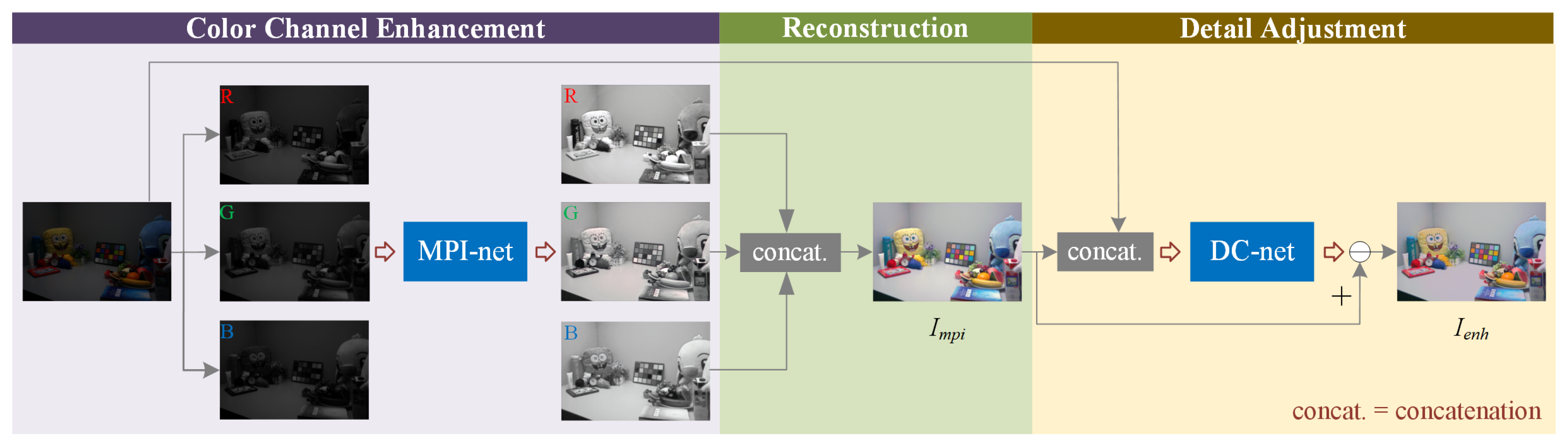
2. Proposed Method
2.1. Multi-Path Interaction Network
2.1.1. Network
2.1.2. Loss Function
2.2. Detail Correction Network
2.2.1. Network
2.2.2. Loss Function
3. Experiments
3.1. Training Details and Dataset
3.2. Comparison with State-of-the-Art Methods
3.2.1. Visual Quality Comparison
3.2.2. Evaluation
3.3. Ablation Study
3.4. Application
4. Conclusions
Author Contributions
Funding
Conflicts of Interest
References
- Zhao, X.; Sun, P.; Xu, Z.; Min, H.; Yu, H. Fusion of 3D LIDAR and camera data for object detection in autonomous vehicle applications. IEEE Sens. J. 2020, 20, 4901–4913. [Google Scholar] [CrossRef] [Green Version]
- Li, J.; Tang, Y.; Zou, X.; Lin, G.; Wang, H. Detection of fruit-bearing branches and localization of litchi clusters for vision-based harvesting robots. IEEE Access 2020, 8, 117746–117758. [Google Scholar] [CrossRef]
- Tang, Y.; Li, L.; Wang, C.; Chen, M.; Feng, W.; Zou, X.; Huang, K. Real-time detection of surface deformation and strain in recycled aggregate concrete-filled steel tubular columns via four-ocular vision. Robot. Comput. Integr. Manuf. 2019, 59, 36–46. [Google Scholar] [CrossRef]
- Tang, Y.; Chen, M.; Lin, Y.; Huang, X.; Huang, K.; He, Y.; Li, L. Vision-based three-dimensional reconstruction and monitoring of large-scale steel tubular structures. Adv. Civ. Eng. 2020, 2020, 1236021. [Google Scholar] [CrossRef]
- Zhang, T.; Chowdhery, A.; Bahl, P.; Jamieson, K.; Banerjee, S. The design and implementation of a wireless video surveillance system. In Proceedings of the Annual International Conference on Mobile Computing and Networking, Paris, France, 7–11 September 2015; pp. 426–438. [Google Scholar]
- Chen, M.; Tang, Y.; Zou, X.; Huang, Z.; Zhou, H.; Chen, S. 3D global mapping of large-scale unstructured orchard integrating eye-in-hand stereo vision and SLAM. Comput. Electron. Agric. 2021, 187, 106237. [Google Scholar] [CrossRef]
- Rashed, H.; Ramzy, M.; Vaquero, V.; El Sallab, A.; Sistu, G.; Yogamani, S. FuseMODNet: Real-Time Camera and LiDAR Based Moving Object Detection for Robust Low-Light Autonomous Driving. In Proceedings of the IEEE International Conference on Computer Vision Workshop, Seoul, Korea, 27–28 October 2019; pp. 2393–2402. [Google Scholar]
- Wang, R.; Zhang, Q.; Fu, C.W.; Shen, X.; Zheng, W.S.; Jia, J. Underexposed photo enhancement using deep illumination estimation. In Proceedings of the IEEE Conference on Computer Vision and Pattern Recognition, Long Beach, CA, USA, 15–20 June 2019; pp. 6842–6850. [Google Scholar]
- Ai, S.; Kwon, J. Extreme low-light image enhancement for surveillance cameras using attention U-Net. Sensors 2020, 20, 495. [Google Scholar] [CrossRef] [PubMed] [Green Version]
- Xu, X.; Wang, S.; Wang, Z.; Zhang, X.; Hu, R. Exploring Image Enhancement for Salient Object Detection in Low Light Images. ACM Trans. Multimed. Comput. Commun. Appl. 2021, 17, 1–19. [Google Scholar]
- Ma, S.; Ma, H.; Xu, Y.; Li, S.; Lv, C.; Zhu, M. A low-light sensor image enhancement algorithm based on HSI color model. Sensors 2018, 18, 3583. [Google Scholar] [CrossRef] [Green Version]
- Stark, J.A. Adaptive image contrast enhancement using generalizations of histogram equalization. IEEE Trans. Image Process. 2000, 9, 889–896. [Google Scholar] [CrossRef] [Green Version]
- Abdullah-Al-Wadud, M.; Kabir, M.H.; Dewan, M.A.A.; Chae, O. A dynamic histogram equalization for image contrast enhancement. IEEE Trans. Consum. Electron. 2007, 53, 593–600. [Google Scholar] [CrossRef]
- Ibrahim, H.; Kong, N.S.P. Brightness preserving dynamic histogram equalization for image contrast enhancement. IEEE Trans. Consum. Electron. 2007, 53, 1752–1758. [Google Scholar] [CrossRef]
- Ying, Z.; Li, G.; Gao, W. A bio-inspired multi-exposure fusion framework for low-light image enhancement. arXiv 2017, arXiv:1711.00591. [Google Scholar]
- Ren, Y.; Ying, Z.; Li, T.H.; Li, G. LECARM: Low-light image enhancement using the camera response model. IEEE Trans. Circuits Syst. Video Technol. 2018, 29, 968–981. [Google Scholar] [CrossRef]
- Land, E.H. The retinex theory of color vision. Sci. Am. 1977, 237, 108–129. [Google Scholar] [CrossRef]
- Fu, X.; Zeng, D.; Huang, Y.; Zhang, X.P.; Ding, X. A weighted variational model for simultaneous reflectance and illumination estimation. In Proceedings of the IEEE Conference on Computer Vision and Pattern Recognition, Las Vegas, NV, USA, 27–30 June 2016; pp. 2782–2790. [Google Scholar]
- Guo, X.; Li, Y.; Ling, H. LIME: Low-light image enhancement via illumination map estimation. IEEE Trans. Image Process. 2016, 26, 982–993. [Google Scholar] [CrossRef]
- Jobson, D.J.; Rahman, Z.; Woodell, G.A. A multiscale retinex for bridging the gap between color images and the human observation of scenes. IEEE Trans. Image Process. 1997, 6, 965–976. [Google Scholar] [CrossRef] [Green Version]
- Fu, X.; Zeng, D.; Huang, Y.; Liao, Y.; Ding, X.; Paisley, J. A fusion-based enhancing method for weakly illuminated images. Signal Process. 2016, 129, 82–96. [Google Scholar] [CrossRef]
- Dong, X.; Wang, G.; Pang, Y.; Li, W.; Wen, J.; Meng, W.; Lu, Y. Fast efficient algorithm for enhancement of low lighting video. In Proceedings of the IEEE International Conference on Multimedia and Expo, Barcelona, Spain, 11–15 July 2011; pp. 1–6. [Google Scholar]
- Wei, C.; Wang, W.; Yang, W.; Liu, J. Deep retinex decomposition for low-light enhancement. In Proceedings of the British Machine Vision Conference, Newcastle, UK, 3–6 September 2018; pp. 1–12. [Google Scholar]
- Xu, K.; Yang, X.; Yin, B.; Lau, R.W.H. Learning to restore low-light images via decomposition-and-enhancement. In Proceedings of the IEEE Conference on Computer Vision and Pattern Recognition, Seattle, WA, USA, 13–19 June 2020; pp. 2281–2290. [Google Scholar]
- Chen, Y.; Yu, M.; Jiang, G.; Peng, Z.; Chen, F. End-to-end single image enhancement based on a dual network cascade model. J. Vis. Commun. Image Represent. 2019, 61, 284–295. [Google Scholar] [CrossRef]
- Lv, F.; Lu, F.; Wu, J.; Lim, C. MBLLEN: Low-Light Image/Video Enhancement Using CNNs. In Proceedings of the British Machine Vision Conference, Newcastle, UK, 3–6 September 2018; p. 220. [Google Scholar]
- Wang, L.W.; Liu, Z.S.; Siu, W.C.; Lun, D.P.K. Lightening network for low-light image enhancement. IEEE Trans. Image Process. 2020, 29, 7984–7996. [Google Scholar] [CrossRef]
- Lore, K.G.; Akintayo, A.; Sarkar, S. LLNet: A deep autoencoder approach to natural low-light image enhancement. Pattern Recognit. 2017, 61, 650–662. [Google Scholar] [CrossRef] [Green Version]
- Jiang, Y.; Gong, X.; Liu, D.; Cheng, Y.; Fang, C.; Shen, X.; Yang, J.; Zhou, P.; Wang, Z. Enlightengan: Deep light enhancement without paired supervision. IEEE Trans. Image Process. 2021, 30, 2340–2349. [Google Scholar] [CrossRef]
- Chen, Y.S.; Wang, Y.C.; Kao, M.H.; Chuang, Y.Y. Deep photo enhancer: Unpaired learning for image enhancement from photographs with gans. In Proceedings of the IEEE Conference on Computer Vision and Pattern Recognition, Seattle, WA, USA, 13–19 June 2018; pp. 6306–6314. [Google Scholar]
- Liu, Y.; Wang, Z.; Zeng, Y.; Zeng, H.; Zhao, D. PD-GAN: Perceptual-Details GAN for Extremely Noisy Low Light Image Enhancement. In Proceedings of the IEEE International Conference on Acoustics, Speech and Signal Processing, Toronto, ON, Canada, 13 May 2021; pp. 1840–1844. [Google Scholar]
- Guo, C.; Li, C.; Guo, J.; Loy, C.C.; Hou, J.; Kwong, S.; Cong, R. Zero-reference deep curve estimation for low-light image enhancement. In Proceedings of the IEEE Conference on Computer Vision and Pattern Recognition, Seattle, WA, USA, 13–19 June 2020; pp. 1780–1789. [Google Scholar]
- Lv, F.; Li, Y.; Lu, F. Attention guided low-light image enhancement with a large scale low-light simulation dataset. Int. J. Comput. Vis. 2021, 129, 2175–2193. [Google Scholar] [CrossRef]
- Ronneberger, O.; Fischer, P.; Brox, T. U-net: Convolutional networks for biomedical image segmentation. In Proceedings of the International Conference on Medical Image Computing and Computer Assisted Intervention, Munich, Germany, 5–9 October 2015; pp. 234–241. [Google Scholar]
- Jiang, Z.; Li, H.; Liu, L.; Men, A.; Wang, H. A Switched View of Retinex: Deep Self-Regularized Low-Light Image Enhancement. arXiv 2021, arXiv:2101.00603. [Google Scholar]
- Sun, K.; Xiao, B.; Liu, D.; Wang, J. Deep high-resolution representation learning for human pose estimation. In Proceedings of the IEEE Conference on Computer Vision and Pattern Recognition, Long Beach, CA, USA, 15–20 June 2019; pp. 5693–5703. [Google Scholar]
- Wang, Z.; Bovik, A.C.; Sheikh, H.R.; Simoncelli, E.P. Image quality assessment: From error visibility to structural similarity. IEEE Trans. Image Process. 2004, 13, 600–612. [Google Scholar] [CrossRef] [PubMed] [Green Version]
- Cai, J.; Gu, S.; Zhang, L. Learning a deep single image contrast enhancer from multi-exposure images. IEEE Trans. Image Process. 2018, 27, 2049–2062. [Google Scholar] [CrossRef] [PubMed]
- Wang, W.; Wei, C.; Yang, W.; Liu, J. GLADNet: Low-light enhancement network with global awareness. In Proceedings of the 13th IEEE International Conference on Automatic Face & Gesture Recognition, Xi’an, China, 15–19 May 2018; pp. 751–755. [Google Scholar]
- Mittal, A.; Soundararajan, R.; Bovik, A.C. Making a “completely blind” image quality analyzer. IEEE Signal Process. Lett. 2012, 20, 209–212. [Google Scholar] [CrossRef]


| Methods | BIMEF | LECARM | MSRCR | MF | LIME | Retinex-Net | Ours |
|---|---|---|---|---|---|---|---|
| PSNR | 14.050 | 15.354 | 15.692 | 17.103 | 17.402 | 17.177 | 19.609 |
| SSIM | 0.628 | 0.598 | 0.596 | 0.541 | 0.575 | 0.508 | 0.772 |
| NIQE | 12.0127 | 12.8758 | 13.0186 | 14.0127 | 13.2720 | 15.8324 | 8.6851 |
| Methods | Without | Ours | |
|---|---|---|---|
| PSNR | 19.145 | 19.321 | 19.609 |
| SSIM | 0.768 | 0.770 | 0.772 |
| NIQE | 9.1392 | 8.8136 | 8.6851 |
Publisher’s Note: MDPI stays neutral with regard to jurisdictional claims in published maps and institutional affiliations. |
© 2021 by the authors. Licensee MDPI, Basel, Switzerland. This article is an open access article distributed under the terms and conditions of the Creative Commons Attribution (CC BY) license (https://creativecommons.org/licenses/by/4.0/).
Share and Cite
Zhao, B.; Gong, X.; Wang, J.; Zhao, L. Low-Light Image Enhancement Based on Multi-Path Interaction. Sensors 2021, 21, 4986. https://doi.org/10.3390/s21154986
Zhao B, Gong X, Wang J, Zhao L. Low-Light Image Enhancement Based on Multi-Path Interaction. Sensors. 2021; 21(15):4986. https://doi.org/10.3390/s21154986
Chicago/Turabian StyleZhao, Bai, Xiaolin Gong, Jian Wang, and Lingchao Zhao. 2021. "Low-Light Image Enhancement Based on Multi-Path Interaction" Sensors 21, no. 15: 4986. https://doi.org/10.3390/s21154986