
Phase Error Analysis and Correction for Crossed-Grating Phase-Shifting Profilometry


Abstract
:1. Introduction
2. Principle
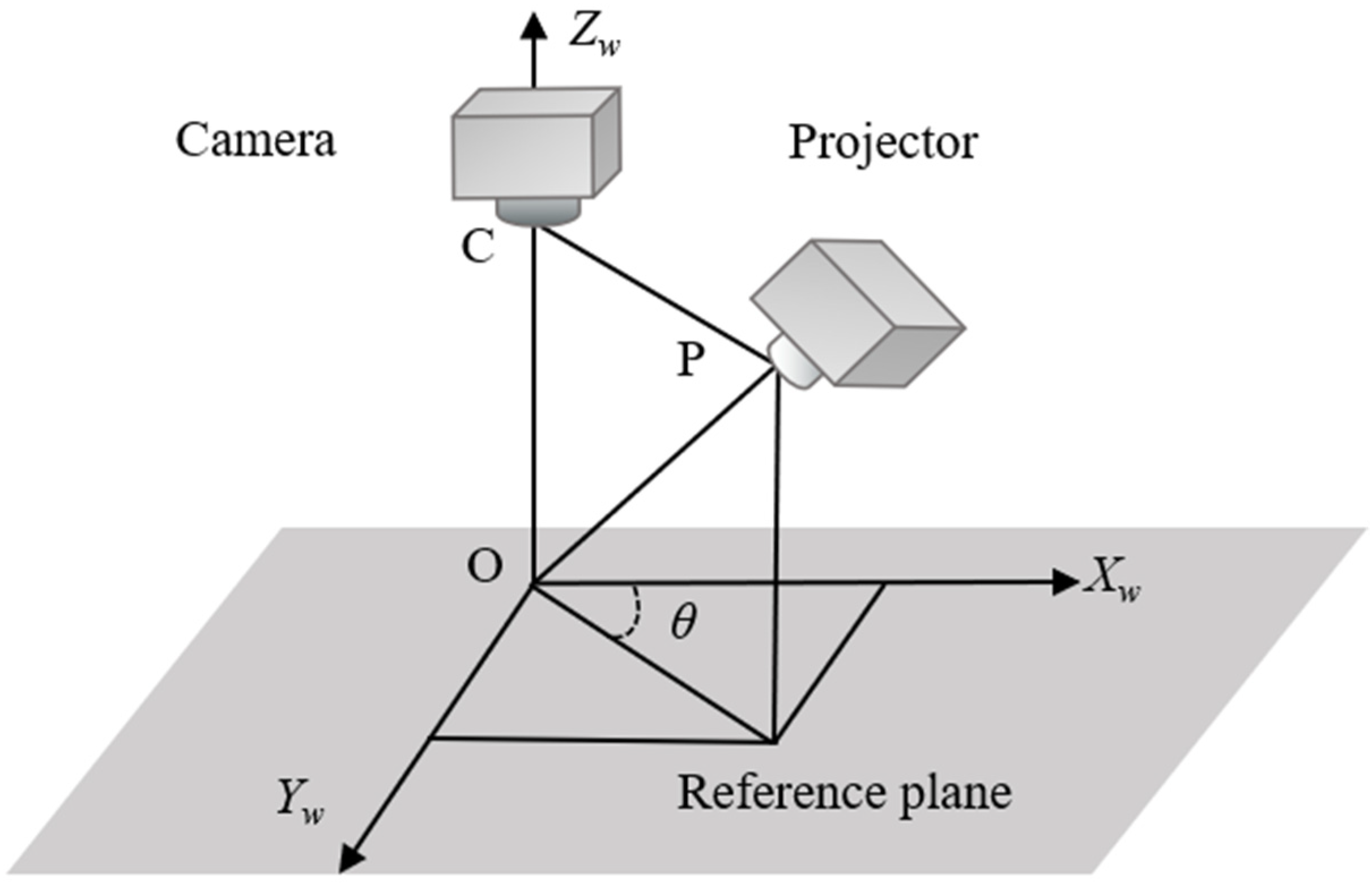
2.1. Principle of Crossed-Grating Phase-Shifting Profilometry
2.2. Principle of Crossed-Grating Phase-Shifting Profilometry
2.3. Phase Error Analysis for Crossed-Grating Phase-Shifting Profilometry
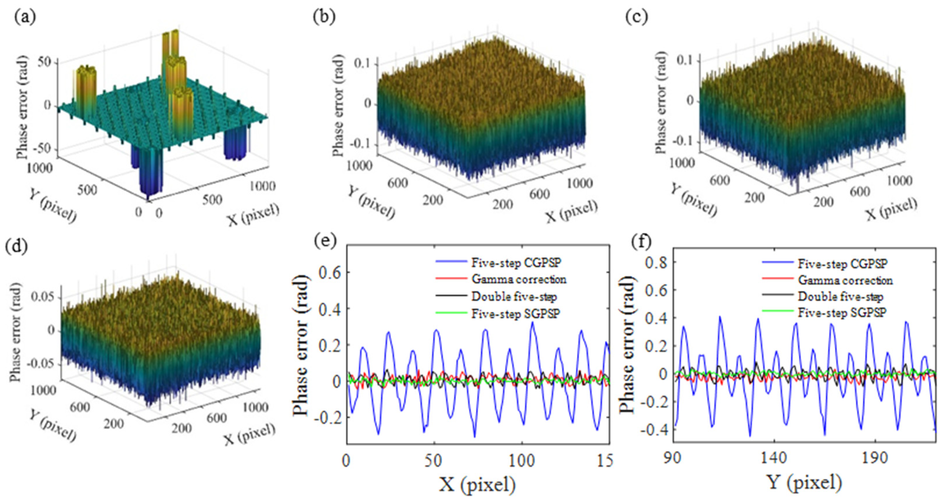
- When N is an odd number, the wrapped phases φxw′ and φyw′ are derived as:where m is a positive integer for describing the harmonic order. The functions F(φx, φy) and G(φx, φy) in Equation (8), and H(φx, φy) and I(φx, φy) in Equation (9) are regarded as the high-order crossed phase error. They are the summation of periodic sinusoidal and cosinusoidal harmonic functions with variables φx and φy, but their mathematical expressions are too complex to be written as explicit functions. Their magnitudes decrease with the increasing of the total number of phase shifts N. Seen from Equations (8) and (9), both φxw′ and φyw′ include periodic phase error caused by the horizontal and vertical high-order harmonics and the crosstalk components. Equation (8) shows that the horizontal phase error is introduced by the mN ± 1th horizontal harmonics, the [(2m − 1)N − 1]/2th vertical harmonics and the crossed phases −[e21sin(φx − φy)]/2 + F(φx, φy) and [e21cos(φx − φy)]/2 + G(φx, φy). Equation (9) shows that the vertical phase error is induced by the 2nd and mN ± 2th horizontal harmonics, the mN ± 1th vertical harmonics and the crossed phases H(φx, φy) and I(φx, φy). For instance, when N = 5 and m = 1, 2, φxw′ includes the horizontal phase error introduced by the horizontal harmonics 4, 6, 9, 11, vertical harmonics 2, 3, 7, 8, and the crossed phases −[e21sin(φx − φy)]/2 + F(φx, φy)|N=5 and [e21cos(φx − φy)]/2 + G(φx, φy)|N=5. φyw′ includes the vertical phase error introduced by the horizontal harmonics 2, 3, 7, 8, 12, the vertical harmonics 4, 6, 9, 11, and the crossed phases H(φx, φy)|N=5 and I(φx, φy)|N=5.
- When N is an even number, φxw′ and φyw′ are derived as:
- There is always the crossed-phase component φx − φy in the horizontal distorted phase;
- There is always the phase error induced by the 2nd horizontal harmonic in the vertical distorted phase;
- The crossed phase component φx − φy and the 2nd horizontal harmonic in Equations (8)–(11) make the large-step phase-shifting method invalid to eliminate the non-linear error in CGPSP.
- When N ≥ 2k + 1, there is always the crossed phase component (k − 1)φx − φy in the horizontal distorted phase;
- When N ≥ 2k + 1, there is always the phase error induced by the kth horizontal harmonic in the vertical distorted phase.
3. Phase Error Correction for Crossed-Grating Phase-Shifting Profilometry
3.1. Double Five-Step Algorithm
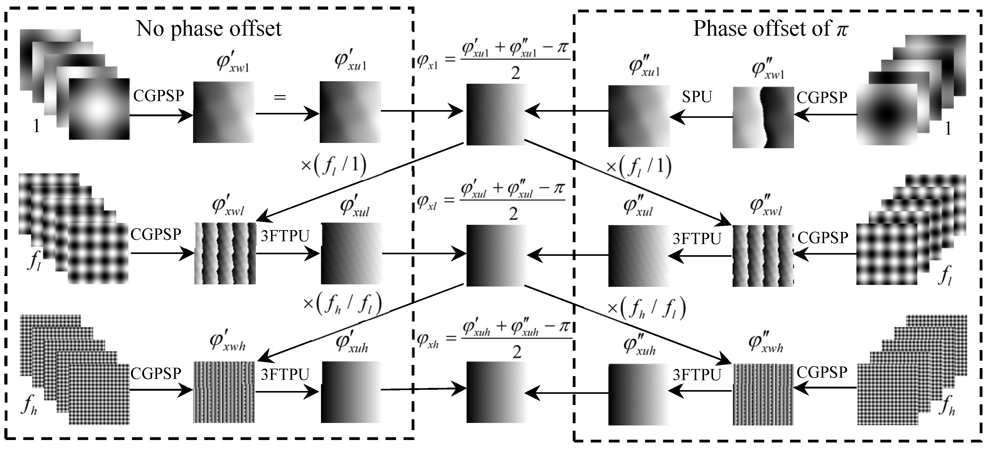
- Step 1: Two unwrapped phases φxw1′ and φxw1″ with non-linearity error are obtained from the single-frequency crossed fringes with and without the initial phase offset of π, respectively. Then, an unwrapped phase φx1 eliminated the second non-linearity error obtained by the double five-step algorithm.
- Step 2: Two wrapped phases φxwl′ and φxwl″ are firstly obtained from the low-frequency (fl) crossed fringes with and without the initial phase offset of π, respectively. Then, combining the unwrapped phase φx1 obtained in Step 1, the two wrapped phases are unwrapped to obtain φxul′ and φxul″, respectively. Finally, an unwrapped phase φxl without the second non-linearity error can be obtained by the double five-step algorithm.
- Step 3: Similarly, two wrapped phases φxwh′ and φxwh″ respectively obtained from high-frequency (fh) crossed fringes with and without the initial phase offset of π are unwrapped to obtain φxuh′ and φxuh″, employing the unwrapped phase φxl obtained in Step 2. The final corrected phase φxh can be obtained by the double five-step algorithm.
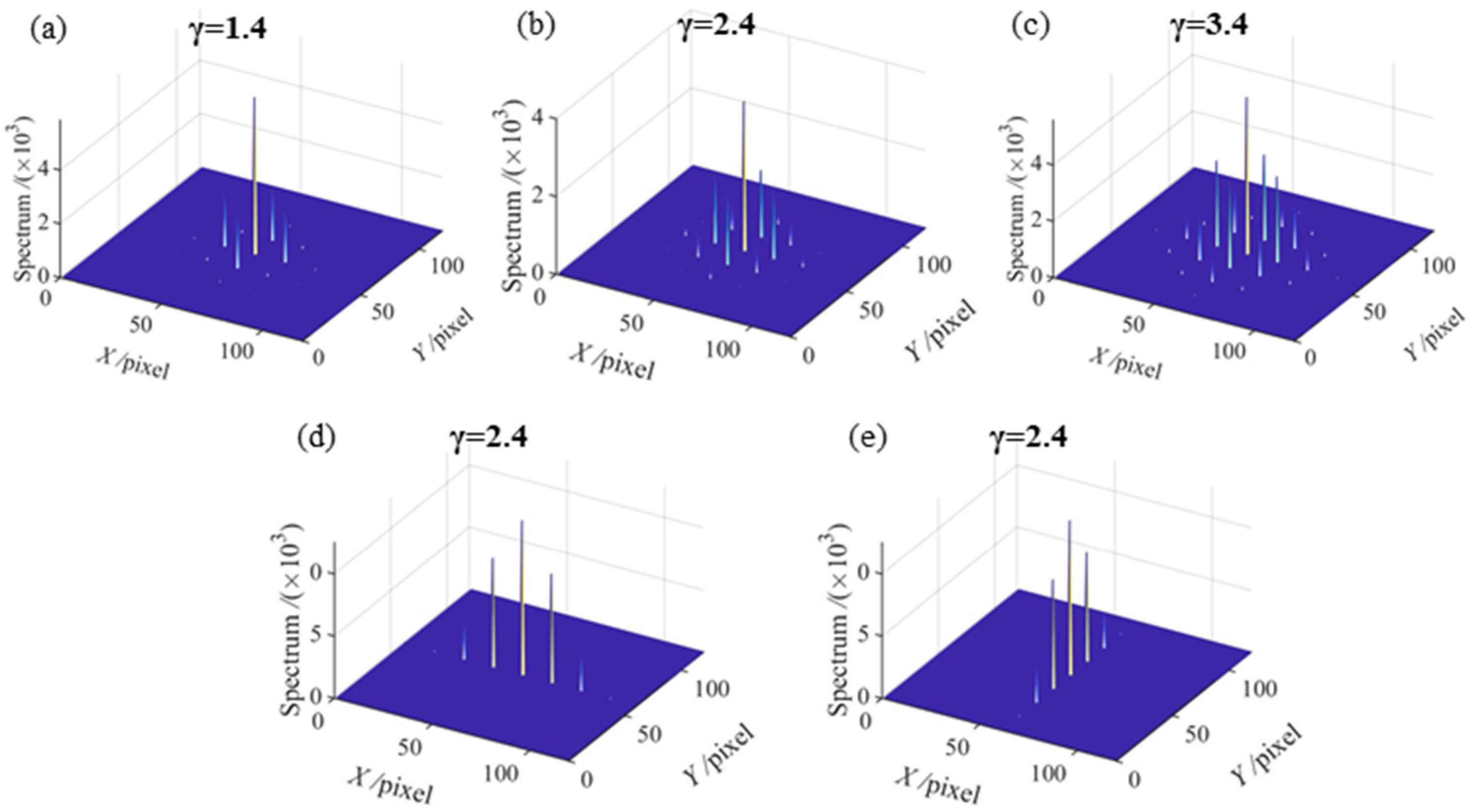
3.2. Gamma Correction Method Based on Probability Distribution Function
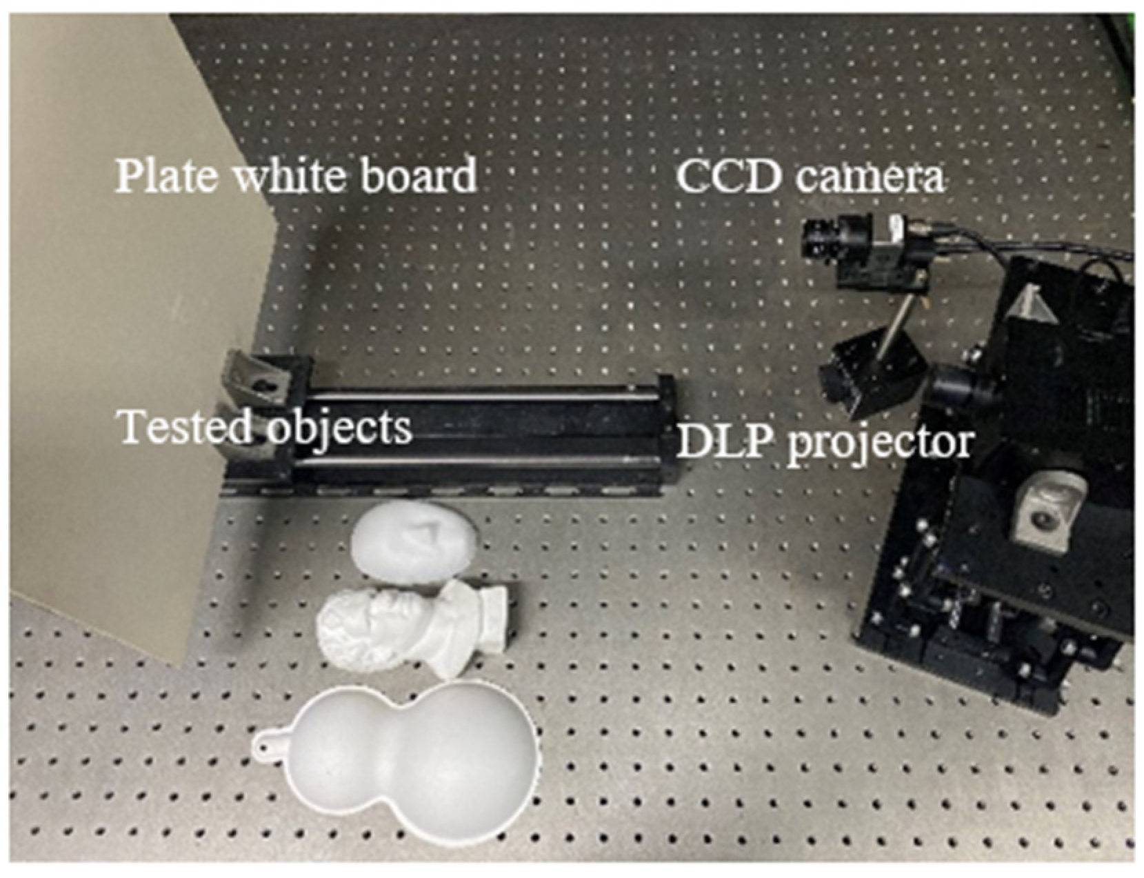
4. Experiments and Discussion
4.1. Phase Calculation of Crossed-Grating Phase-Shifting Profilometry
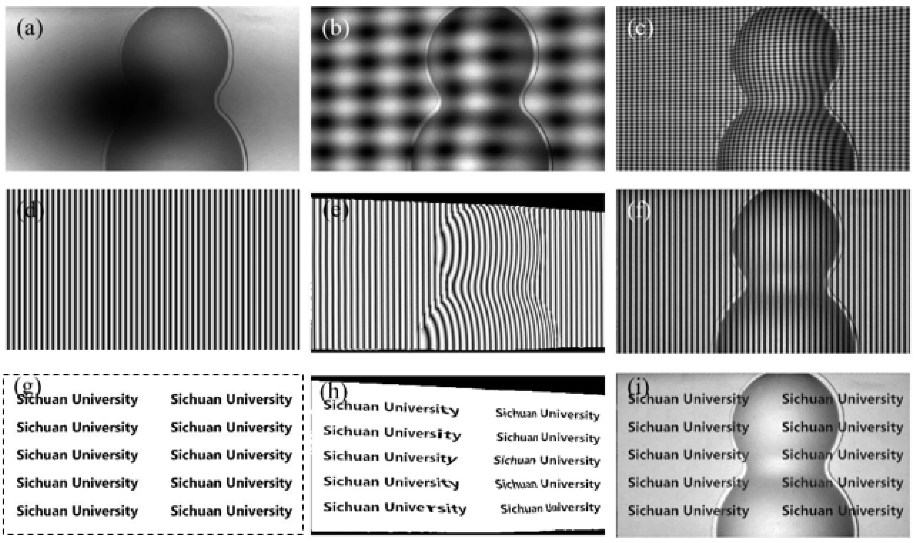
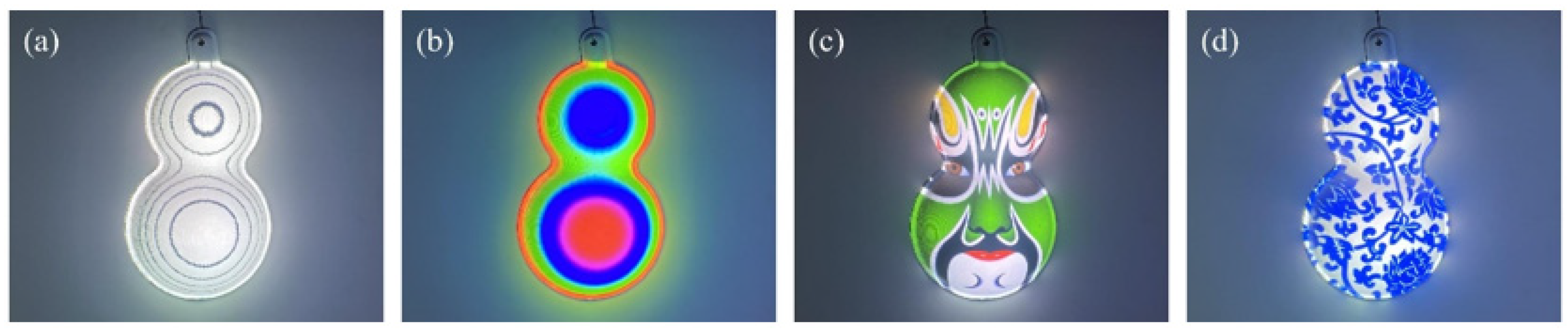
4.2. Inverse Pattern Projection Based on CGPSP
5. Conclusions
Author Contributions
Funding
Institutional Review Board Statement
Informed Consent Statement
Data Availability Statement
Conflicts of Interest
References
- Zuo, C.; Feng, S.; Huang, L.; Tao, T.; Yin, W.; Chen, Q. Phase shifting algorithms for fringe projection profilometry: A review. Opt. Lasers Eng. 2018, 109, 23–59. [Google Scholar] [CrossRef]
- Srinivasan, V.; Liu, H.; Halioua, M. Automated phase-measuring profilometry of 3-D diffuse objects. Appl. Opt. 1984, 23, 3105–3108. [Google Scholar] [CrossRef] [PubMed]
- Gorthi, S.; Rastogi, P. Fringe projection techniques: Whither we are? Opt. Lasers Eng. 2010, 48, 133–140. [Google Scholar] [CrossRef] [Green Version]
- Kang, S.; Ume, I. Dynamic digital fringe projection technique for measuring the warpage of unpainted PBGA packages and boards. Int. J. Adv. Manuf. Technol. 2018, 96, 3235–3249. [Google Scholar] [CrossRef]
- Kim, S.; Choi, Y.; Oh, J. Reverse engineering: High speed digitization of free-form surfaces by phase-shifting grating projection moiré topography. Int. J. Mach. Tools Manuf. 1999, 39, 389–401. [Google Scholar] [CrossRef]
- Ford, K.; Myer, G.; Hewett, T. Reliability of landing 3D motion analysis: Implications for longitudinal analyses. Med. Sci. Sports Exerc. 2007, 39, 2021–2028. [Google Scholar] [CrossRef] [PubMed]
- Zhang, S.; Yau, S. Generic nonsinusoidal phase error correction for tree-dimensional shape measurement using a digital video projector. Appl. Opt. 2007, 46, 36–43. [Google Scholar] [CrossRef]
- Li, S.; Chen, W.; Su, X. Quality-guided phase unwrapping technique: Comparison of quality maps and guiding strategies. Appl. Opt. 2011, 50, 6214–6224. [Google Scholar]
- Zhang, Q.; Han, Y.; Wu, Y. Comparison and combination of three spatial phase unwrapping algorithms. Opt. Rev. 2019, 26, 380–390. [Google Scholar] [CrossRef]
- Flynn, T. Two-dimensional phase unwrapping with minimum weighted discontinuity. J. Opt. Soc. Am. A 1997, 14, 2692–2701. [Google Scholar] [CrossRef]
- Zuo, C.; Huang, L.; Zhang, M.; Chen, Q.; Asundi, A. Temporal phase unwrapping algorithms for fringe projection profilometry: A comparative review. Opt. Lasers Eng. 2016, 85, 84–103. [Google Scholar] [CrossRef]
- Huntley, J.; Saldner, H. Temporal phase-unwrapping algorithm for automated interferogram analysis. Appl. Opt. 1993, 32, 3047–3052. [Google Scholar] [CrossRef]
- Gushov, V.; Solodkin, Y. Automatic processing of fringe patterns in integer interferometers. Opt. Lasers Eng. 1991, 14, 311–324. [Google Scholar] [CrossRef]
- Huang, L.; Idir, M.; Zuo, C.; Asundi, A. Review of phase measurement deflectometry. Opt. Lasers Eng. 2018, 107, 247–257. [Google Scholar] [CrossRef]
- Li, W.; Bothe, T.; Osten, W.; Kalms, M. Object adapted pattern projection—Part I: Generation of inverse patterns. Opt. Lasers Eng. 2004, 41, 31–50. [Google Scholar] [CrossRef]
- Feng, S.; Zuo, C.; Zhang, L.; Tao, T.; Hu, Y.; Yin, W.; Qian, J.; Chen, Q. Calibration of fringe projection profilometry: A comparative review. Opt. Lasers Eng. 2021, 143, 106622. [Google Scholar] [CrossRef]
- Liu, Y.; Olesch, E.; Yang, Z.; Hausler, G.; Su, X. A novel one-dimensional phase-shift technique by using crossed fringe for phase measuring deflectometry. Proc. SPIE 2019, 9302, 93020X. [Google Scholar]
- Kamagara, A.; Wang, X.; Li, S. Nonlinear gamma correction via normed bicoherence minimization in optical fringe projection metrology. Opt. Eng. 2018, 57, 034107. [Google Scholar] [CrossRef]
- Pan, B.; Qian, K.; Huang, L.; Asundi, A. Phase error analysis and compensation for nonsinusoidal waveforms in phase-shifting digital fringe projection profilometry. Opt. Lett. 2009, 34, 416–418. [Google Scholar] [CrossRef]
- Zhang, S. Comparative study on passive and active projector nonlinear gamma calibration. Appl. Opt. 2015, 54, 3834–3841. [Google Scholar] [CrossRef]
- Hoang, T.; Pan, B.; Nguyen, D.; Wang, Z. Generic gamma correction for accuracy enhancement in fringe-projection profilometry. Opt. Lett. 2010, 35, 1992–1994. [Google Scholar] [CrossRef] [PubMed]
- Guo, H.; He, H.; Chen, M. Gamma correction for digital fringe projection profilometry. Appl. Opt. 2004, 43, 2906–2914. [Google Scholar] [CrossRef] [PubMed]
- Yu, X.; Liu, Y.; Liu, N.; Fan, M.; Su, X. Flexible gamma calculation algorithm based on probability distribution function in digital fringe projection system. Opt. Express 2019, 27, 32047–32057. [Google Scholar] [CrossRef] [PubMed]
- Baker, M.; Xi, J.; Chicharo, J. Elimination of gamma non-linear luminance effects for digital video projection phase measuring profilometers. In Proceedings of the 4th IEEE International Symposium on Electronic Design, Test and Applications, Hong Kong, China, 23–25 January 2008; pp. 496–501. [Google Scholar]
- Lei, S.; Zhang, S. Flexible 3-D shape measurement using projector defocusing. Opt. Lett. 2009, 34, 3080–3082. [Google Scholar] [CrossRef] [PubMed]
- Zhang, S.; Huang, P. Phase error compensation for a 3-D shape measurement system based on the phase-shifting method. Opt. Eng. 2007, 46, 063601. [Google Scholar]
- Huang, P.; Hu, Q.; Chiang, F. Double three-step phase-shifting algorithm. Appl. Opt. 2002, 41, 4503–4509. [Google Scholar] [CrossRef]
- Cai, Z.; Liu, X.; Jiang, H.; He, D.; Peng, X.; Huang, S.; Zhang, Z. Flexible phase error compensation based on Hilbert transform in phase shifting profilometry. Opt. Express. 2015, 23, 25171–25181. [Google Scholar] [CrossRef]
- Zheng, D.; Da, F.; Qian, K.; Seah, H. Phase error analysis and compensation for phase shifting profilometry with projector defocusing. Appl. Opt. 2019, 55, 5721–5728. [Google Scholar] [CrossRef]
- Wang, Z.; Nguyen, D.; Barnes, J. Some practical considerations in fringe projection profilometry. Opt. Lasers Eng. 2010, 48, 218–225. [Google Scholar] [CrossRef]
- Li, W.; Bothe, T.; Kalms, M.; Kopylow, C.; Juptner, W. Applications for inverse pattern projection. Proc. SPIE 2003, 5144, 492–503. [Google Scholar]
- Bothe, T.; Gesierich, A.; Li, W.; Kopylow, C.; Kopp, N.; Juptner, W. 3D-camera for scene capturing and augmented reality applications. In Proceedings of the 3DTV Conference, Kos, Greece, 7–9 May 2007; pp. 1–4. [Google Scholar]
- Liu, K.; Wang, Y.; Lau, D.; Hao, Q.; Hassebrook, L. Gamma model and its analysis for phase measuring profilometry. J. Opt. Soc. Am. A 2010, 27, 553–562. [Google Scholar] [CrossRef] [PubMed]
- Huang, P.; Zhang, C.; Chiang, F. High-speed 3-D shape measurement based on digital fringe projection. Opt. Eng. 2002, 4, 163–168. [Google Scholar] [CrossRef]
- Zhao, W.; Su, X.; Chen, W. Discussion on accurate phase-height mapping in fringe projection profilometry. Opt. Eng. 2017, 56, 104109. [Google Scholar] [CrossRef]


| Method | STD of the Horizontal Phase Errors (rad) | STD of the Vertical Phase Errors (rad) |
|---|---|---|
| Five-step CGPSP | 19.557 | 19.557 |
| Double five-step algorithm | 0.046 | 0.046 |
| Five-step SGPSP | 0.002 | 0.002 |
| Case | Pre-Encoded Values γp | |
|---|---|---|
| Horizontal Sinusoidal Fringe | Vertical Sinusoidal Fringe | |
| 1 | 1.701 | 1.698 |
| 2 | 1.697 | 1.689 |
| 3 | 1.680 | 1.673 |
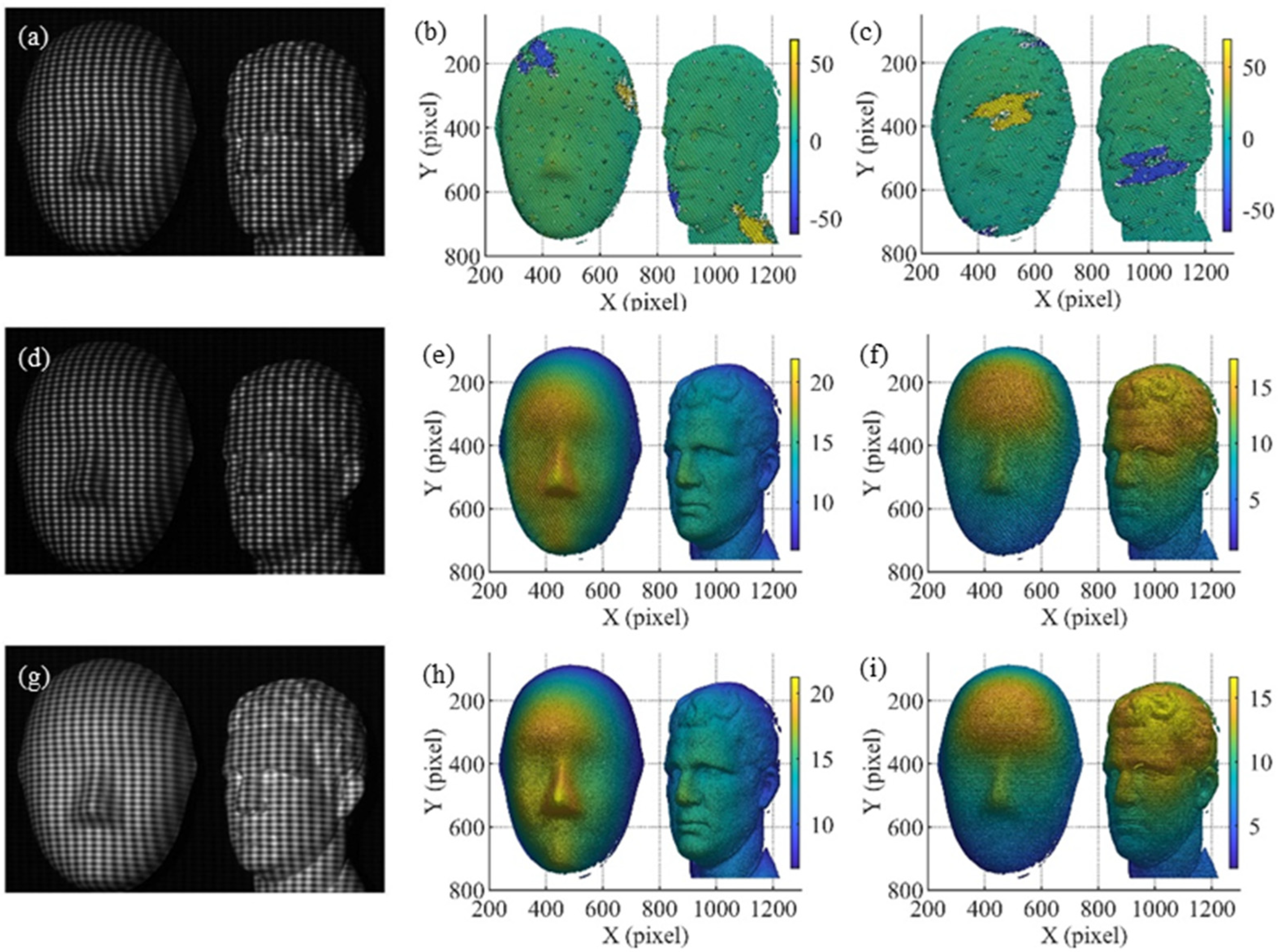
| Method | STD of the Horizontal Phase Errors (rad) | STD of the Vertical Phase Errors (rad) | Number of Fringe Patterns |
|---|---|---|---|
| Five-step CGPSP | 12.974 | 11.711 | 15 |
| Double five-step algorithm | 0.035 | 0.037 | 30 |
| Gamma correction | 0.026 | 0.029 | 15 |
| Five-step SGPSP | 0.012 | 0.015 | 30 |
Publisher’s Note: MDPI stays neutral with regard to jurisdictional claims in published maps and institutional affiliations. |
© 2021 by the authors. Licensee MDPI, Basel, Switzerland. This article is an open access article distributed under the terms and conditions of the Creative Commons Attribution (CC BY) license (https://creativecommons.org/licenses/by/4.0/).
Share and Cite
Li, F.; Chen, W. Phase Error Analysis and Correction for Crossed-Grating Phase-Shifting Profilometry. Sensors 2021, 21, 6475. https://doi.org/10.3390/s21196475
Li F, Chen W. Phase Error Analysis and Correction for Crossed-Grating Phase-Shifting Profilometry. Sensors. 2021; 21(19):6475. https://doi.org/10.3390/s21196475
Chicago/Turabian StyleLi, Fuqian, and Wenjing Chen. 2021. "Phase Error Analysis and Correction for Crossed-Grating Phase-Shifting Profilometry" Sensors 21, no. 19: 6475. https://doi.org/10.3390/s21196475