
Investigation on Wireless Link for Medical Telemetry Including Impedance Matching of Implanted Antennas


Abstract
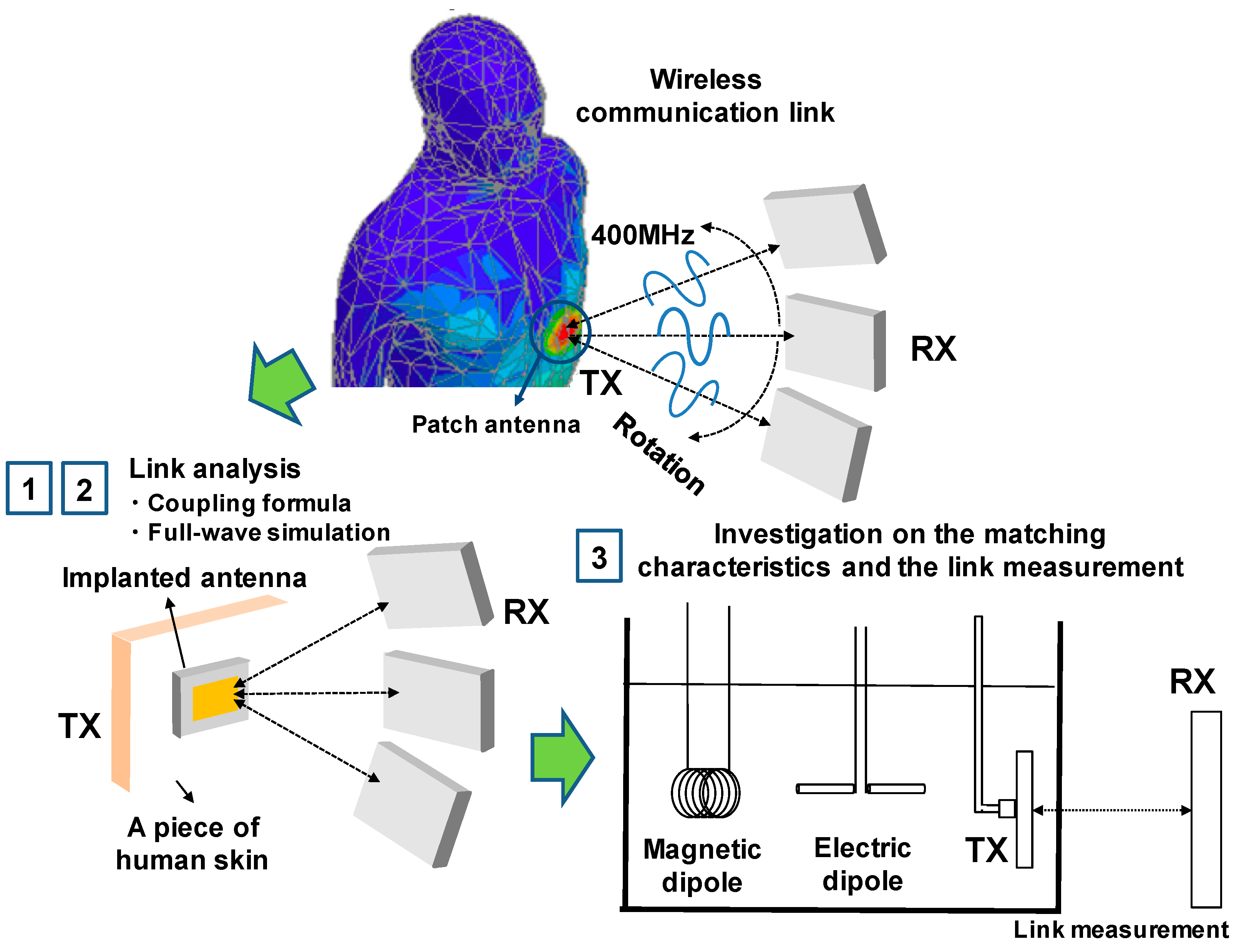
:1. Introduction
2. Computation of the Antenna Coupling in the Near-Field and Far-Field Region
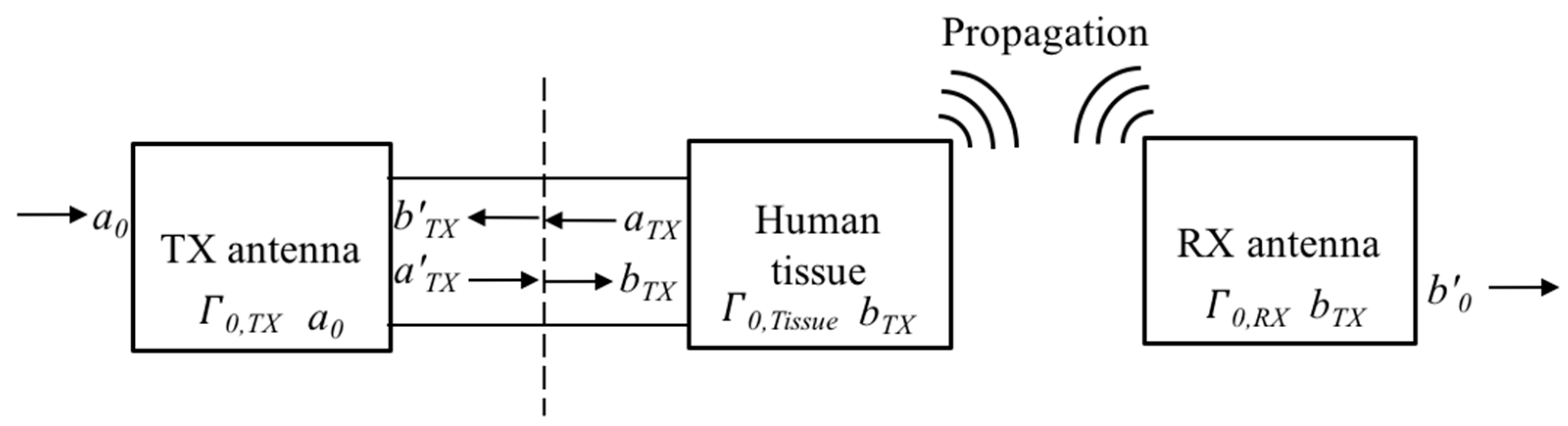
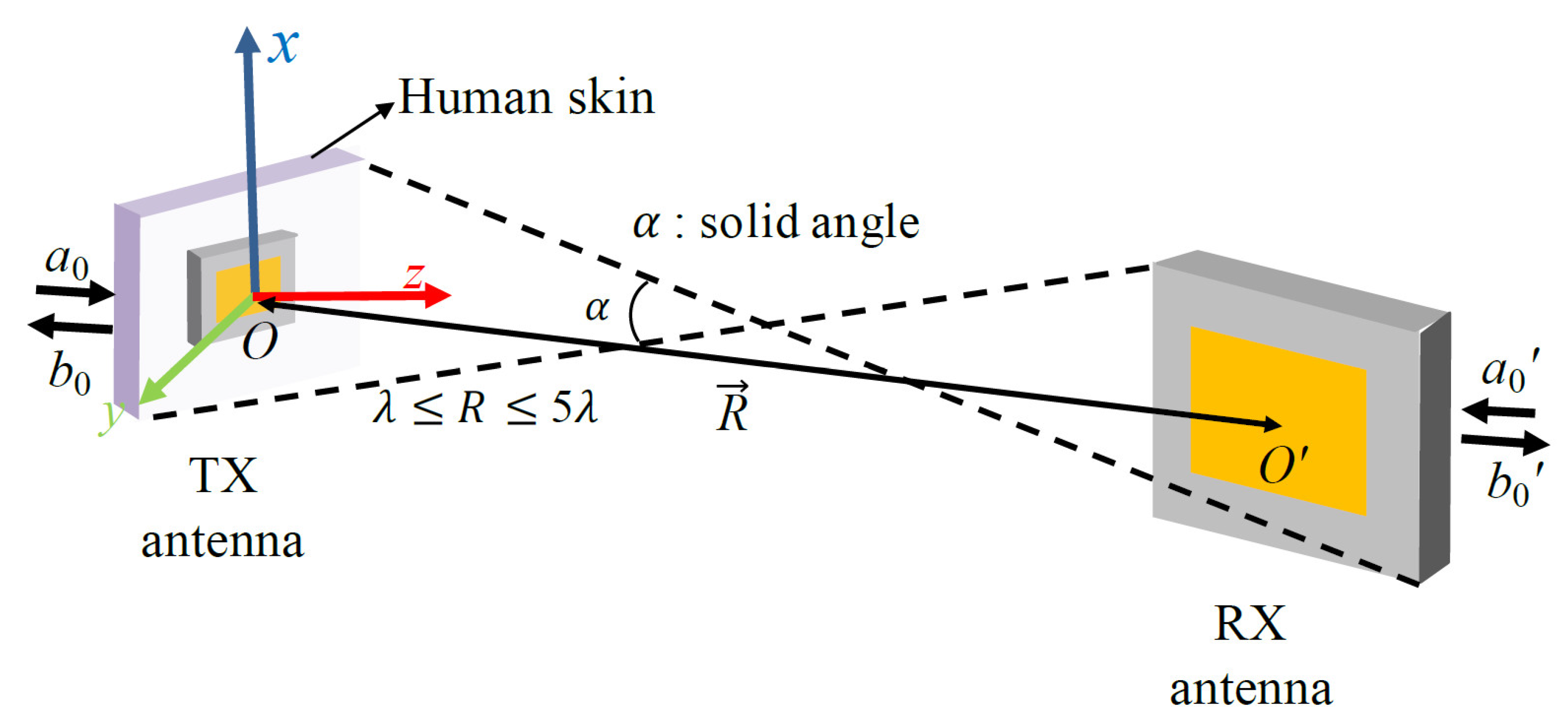
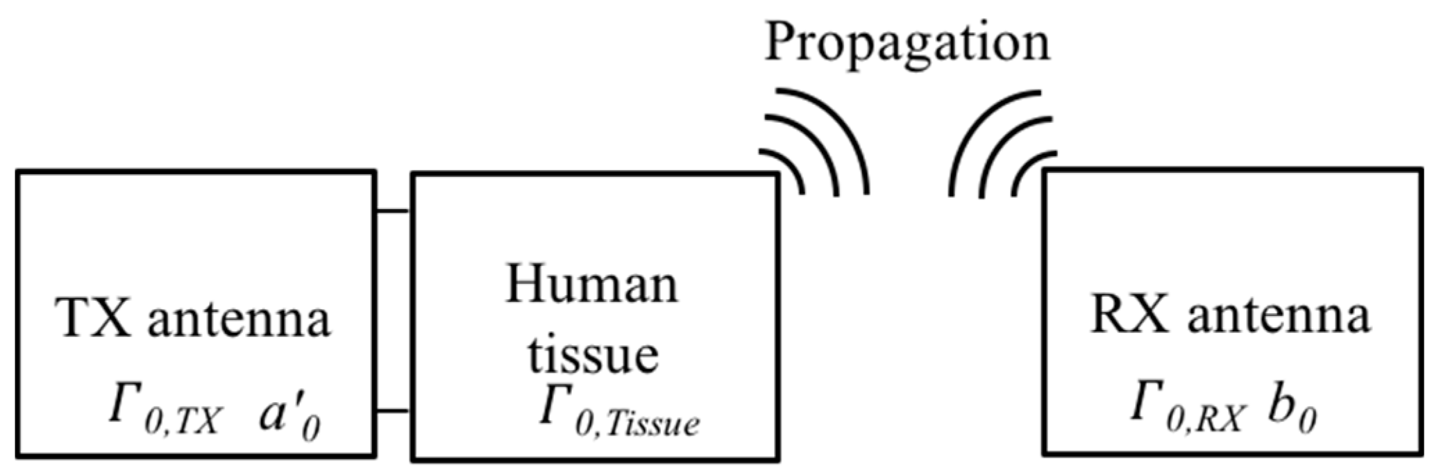
2.1. Revisiting the Integral Coupling Formula
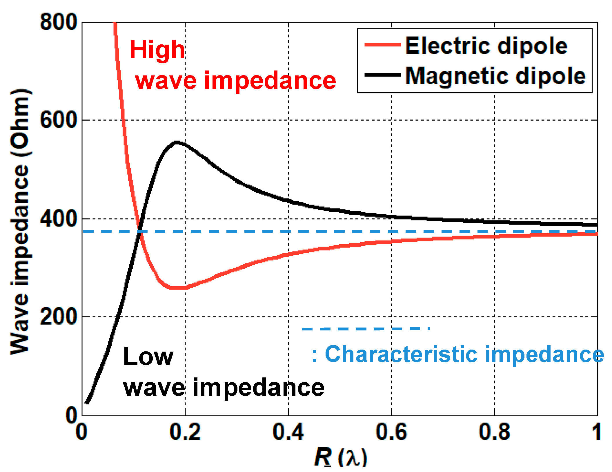
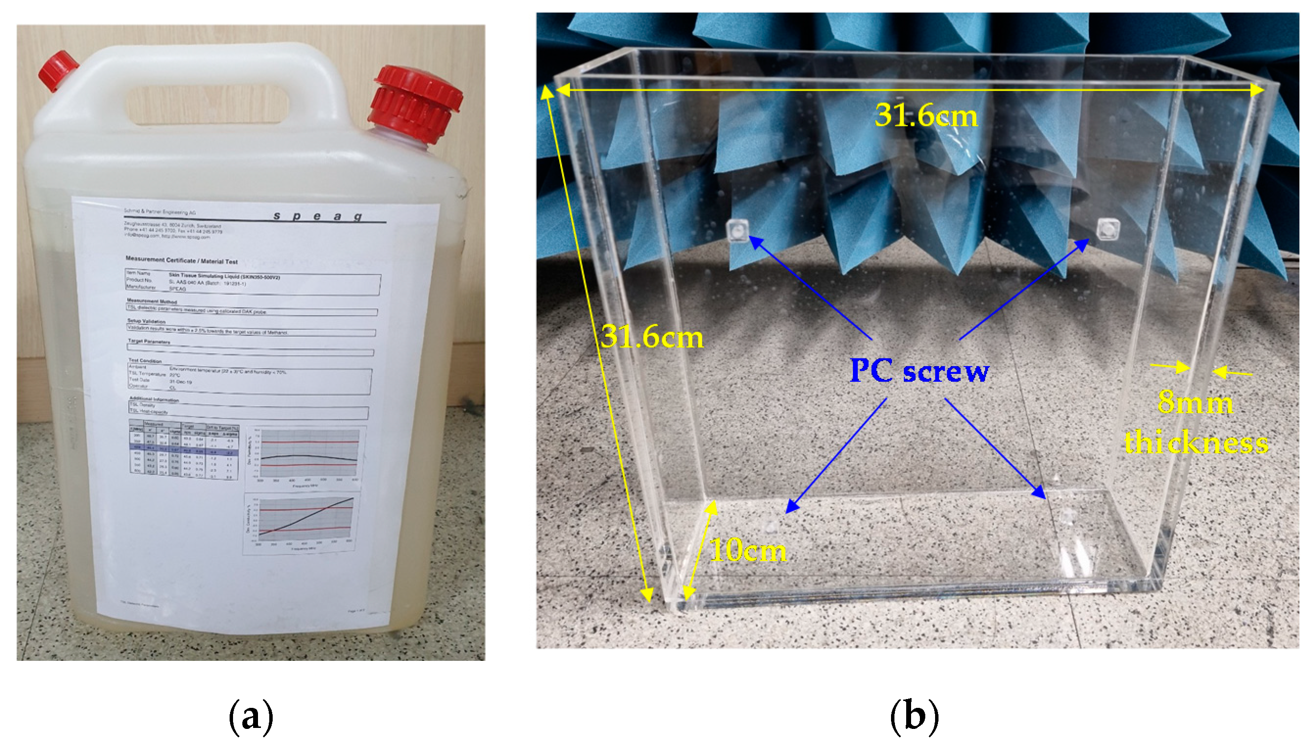
2.2. Electromagnetic Characterization of Implanted Antennas
3. Results
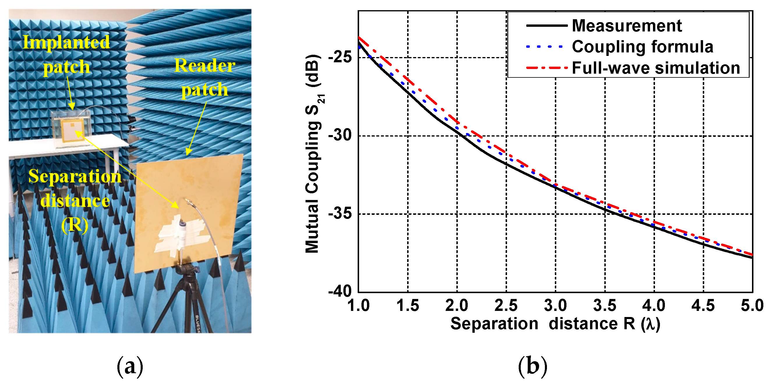
3.1. Calculation of the Link between Two Antennas
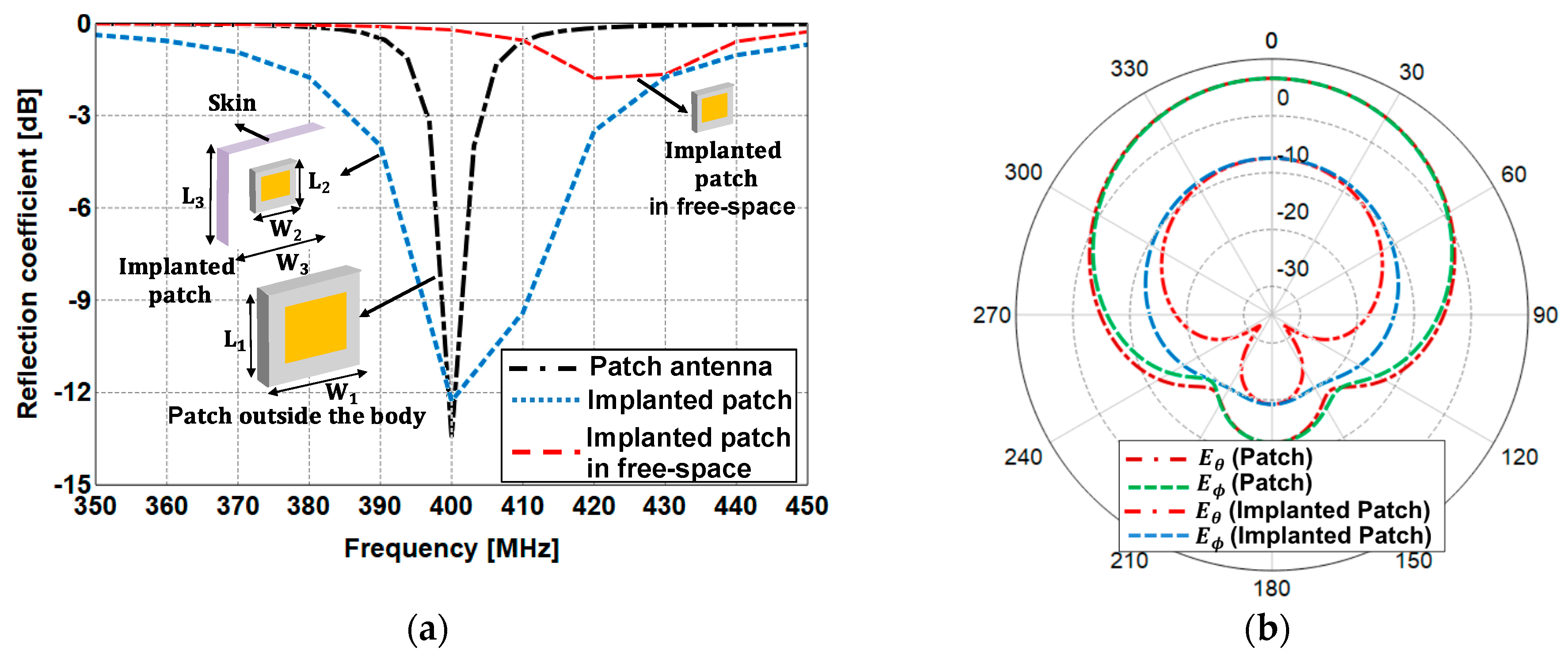
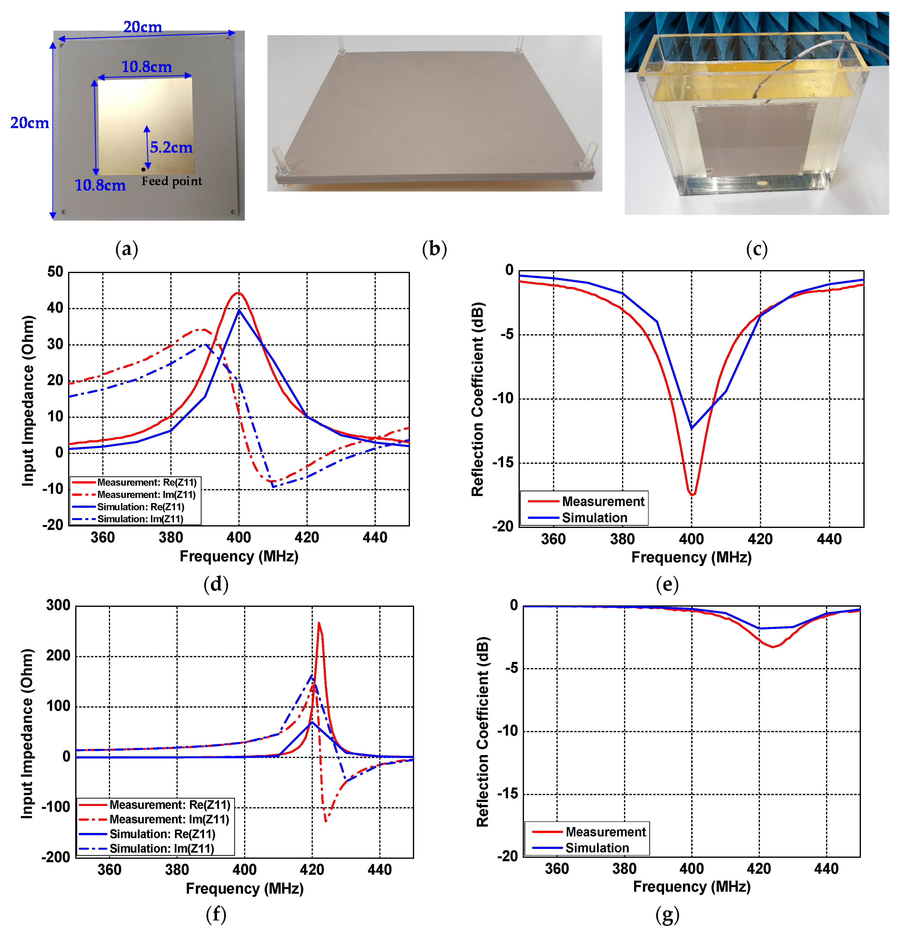
3.1.1. Antenna Design Used for the Link Analysis
3.1.2. Free-Space Link Analysis
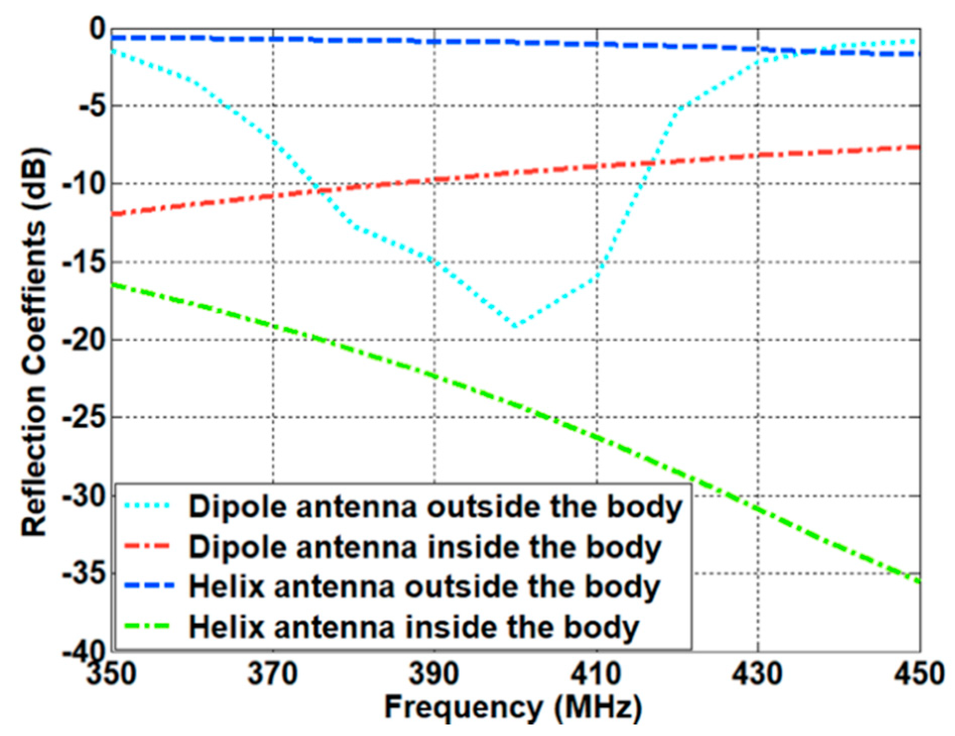
3.1.3. Link between the Two Antennas Inside and Outside the Human Body
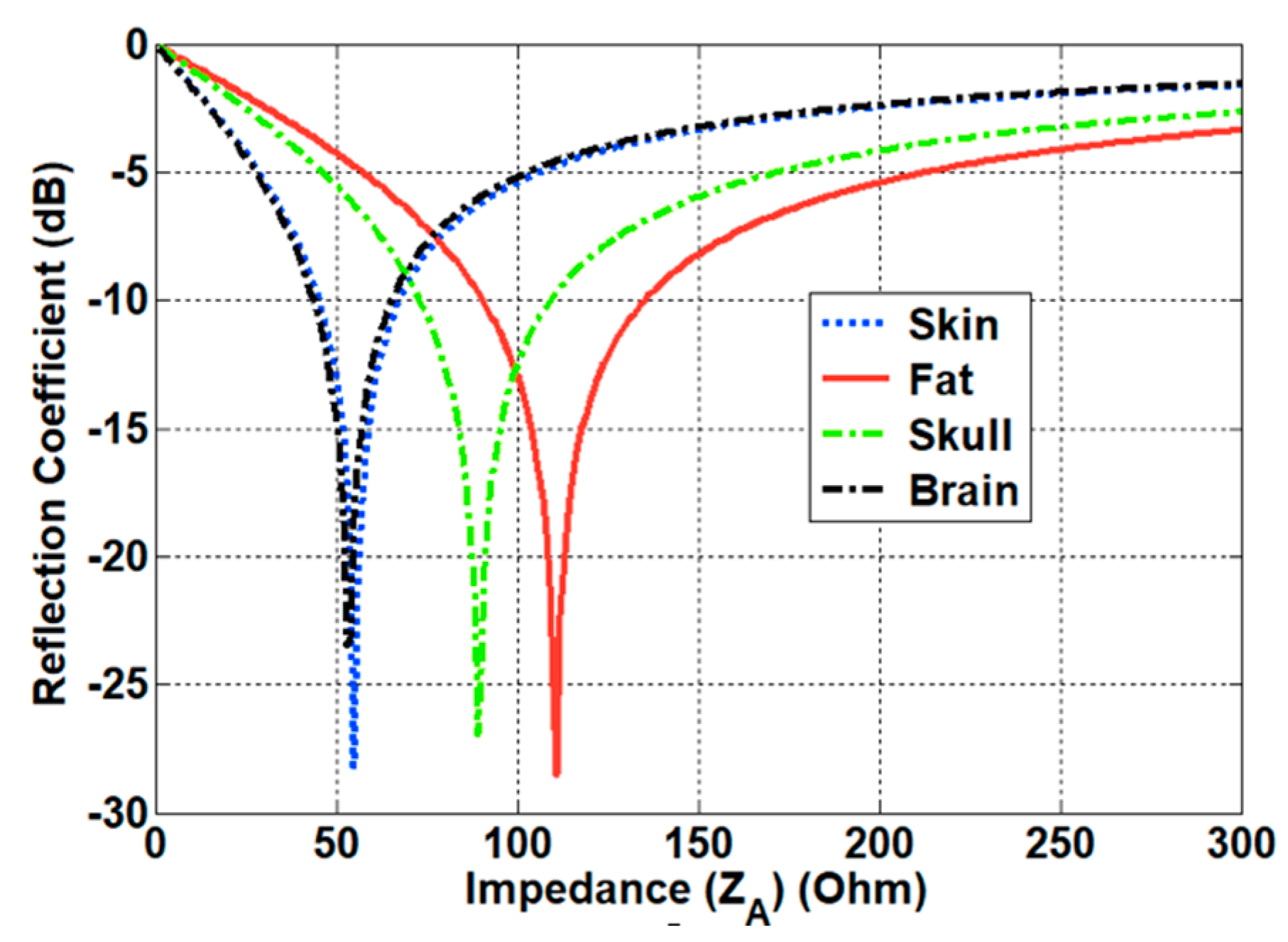
3.2. Matching Characteristics Inside and Outside the Human Body
4. Measurements
5. Discussion
Author Contributions
Funding
Data Availability Statement
Acknowledgments
Conflicts of Interest
Appendix A
References
- Izdebski, P.; Rajagopalan, H.; Rahmat-Samii, Y. Conformal Ingestible Capsule Antenna: A Novel Chandelier Meandered Design. IEEE Trans. Antennas Propag. 2009, 57, 900–909. [Google Scholar] [CrossRef]
- Rao, S.; Llombart, N.; Moradi, E.; Koski, K.; Bjorninen, T.; Sydanheimo, L.; Rabaey, J.; Carmena, J.; Rahmat-Samii, Y.; Ukkonen, L. Miniature implantable and wearable on-body antennas: Towards the new era of wireless body-centric. IEEE Antennas Propag. Mag. 2014, 56, 271–291. [Google Scholar] [CrossRef]
- Khan, S.R.; Pavuluri, S.K.; Cummins, G.; Desmulliez, M.P.Y. Wireless Power Transfer Techniques for Implantable Medical Devices: A Review. Sensors 2020, 20, 3487. [Google Scholar] [CrossRef]
- Basaeri, H.; Christensen, D.B.; Roundy, S. A Review of Acoustic Power Transfer for Bio-medical Implants. Smart Mater. Struct. 2016, 25, 123001. [Google Scholar] [CrossRef]
- Shadid, R.; Haerinia, M.; Roy, S.; Noghanian, S. Hybrid Inductive Power Transfer and Wireless Antenna System for Biomedical Implanted Devices. Prog. Electromagn. Res. C 2018, 88, 77–88. [Google Scholar]
- Monti, G.; Tarricone, L.; Trane, C. Experimental Characterization of a 434 MHz Wireless Energy Link for Medical Applications. Prog. Electromagn. Res. C 2012, 30, 53–64. [Google Scholar] [CrossRef] [Green Version]
- Yakovlev, A.; Kim, S.; Poon, A. Implantable Biomedical Devices: Wireless Powering and Communication. IEEE Commun. Mag. 2012, 50, 152–159. [Google Scholar] [CrossRef]
- Kim, J.; Rahmat-Samii, Y. Implanted Antennas inside a Human Body: Simulations, Designs and Characterizations. IEEE Trans. Microw. Theory Tech. 2004, 52, 1934–1943. [Google Scholar] [CrossRef]
- Song, L.; Rahmat-Samii, Y. An End-to-End Implanted Brain–Machine Interface Antenna System Performance Characterizations and Development. IEEE Trans. Antennas Propag. 2017, 65, 3399–3408. [Google Scholar] [CrossRef]
- Abid, A. Wireless Power Transfer to Millimeter-Sized Gastrointestinal Electronics Validated in a Swine Model. Sci. Rep. 2017, 7, 46745. [Google Scholar] [CrossRef] [PubMed]
- Shaw, T.; Mitra, D. Metasurface-based Radiative Near-field Wireless Power Transfer System for Implantable Medical Devices. IET Microw. Antennas Propag. 2019, 13, 1974–1982. [Google Scholar] [CrossRef]
- Pace, J.R. Asymptotic formulas for coupling between two antennas in the Fresnel region. IEEE Trans. Antennas Propag. 1969, AP-17, 285–291. [Google Scholar] [CrossRef]
- Kim, I.; Xu, S.; Rahmat-Samii, Y. Generalised Correction to the Friis Formula: Quick Determination of the Coupling in the Fresnel Region. IET Microw. Antenna Propag. 2013, 7, 1092–1101. [Google Scholar] [CrossRef]
- Kim, I.; Lee, S.-G.; Lee, J.-H. Derivation of Far-field Gain Using the Gain Reduction Effect in a Fresnel Regions. Appl. Comput. Electromagn. Soc. J. 2020, 35, 3399–3408. [Google Scholar]
- Kerns, D.M. Plane-Wave Scattering Matrix Theory for Antenna-Antenna Interaction; Technical Report; National Bureau of Standards: Boulder, CO, USA, 1981.
- Yaghjian, A.D. Efficient Computation of Antenna Coupling and Fields within the Near-Field Region. IEEE Trans. Antennas Propag. 1982, AP-30, 113–128. [Google Scholar] [CrossRef] [Green Version]
- Francis, M.H.; Stubenrauch, C.F. Comparison of Measured and Calculated Antenna Sidelobe Coupling Loss in the Near Field Using Approximate Far-field Data. IEEE Trans. Antennas Propag. 1988, AP-36, 438–441. [Google Scholar] [CrossRef]
- Akgiray, A.H.; Rahmat-Samii, Y. Mutual Coupling between Two Arbitrarily Oriented and Positioned Antennas in Near- and Far-field Regions. In Proceedings of the 2010 URSI International Symposium on Electromagnetic Theory, Berlin, Germany, 16–19 August 2010. [Google Scholar]
- Kim, I.; Lee, C.-H.; Lee, J.-H. On Computing the Mutual Coupling between Two Antennas. IEEE Trans. Antennas Propag. 2020, 68, 6557–6565. [Google Scholar] [CrossRef]
- Kim, I.; Lee, J.-H. Theoretical Calculation of Power Densities in the Near-field Region of Phased Array Antenna. Microw. Opt. Technol. Lett. 2021, 63, 367–371. [Google Scholar] [CrossRef]
- Sarjoghian, S.; Rahimian, A.; Alfadhl, Y.; Saunders, T.G.; Liu, J.; Parini, C.G. Hybrid Development of a Compact Antenna Based on a Novel Skin-Matched Ceramic Composite for Body Fat Measurement. Electronics 2020, 9, 2139. [Google Scholar] [CrossRef]
- Yamaguchi, T.; Okumura, Y.; Amemiya, Y. Wave Impedance in the Near Field around the Fundamental Electromagnetic Radiating Elements. Electron. Commun. Jpn. 1991, 74, 86–95. [Google Scholar] [CrossRef]
- Paul, C.R. Introduction to Electromagnetic Compatibility; John Wiley: New York, NY, USA, 1992. [Google Scholar]
- Yang, F.; Rahmat-Samii, Y. Reflection Phase Characterizations of the EBG Ground Plane for Low Profile Wire Antenna Applications. IEEE Trans. Antennas Propag. 2003, 51, 2691–2703. [Google Scholar] [CrossRef] [Green Version]


| Methods | Effective Range | Accuracy | Computational Complexity |
|---|---|---|---|
| Inductive coupling [5,6,7] | Non-radiative reactive near-field | High | High |
| Radiative Mid-field [10,11] | Radiative near-field and far-field region | Low | High |
| Coupling formula [16,17,18,19,20] | Radiative near-field and far-field region | High | Low |
| Tissue | Impedance (ZTissue) | |
|---|---|---|
| Skin | 46.7 | 55.2 |
| Fat | 11.6 | 110.7 |
| Skull | 17.8 | 89.4 |
| Brain | 49.7 | 53.5 |
Publisher’s Note: MDPI stays neutral with regard to jurisdictional claims in published maps and institutional affiliations. |
© 2021 by the authors. Licensee MDPI, Basel, Switzerland. This article is an open access article distributed under the terms and conditions of the Creative Commons Attribution (CC BY) license (http://creativecommons.org/licenses/by/4.0/).
Share and Cite
Kim, I.; Lee, S.-G.; Nam, Y.-H.; Lee, J.-H. Investigation on Wireless Link for Medical Telemetry Including Impedance Matching of Implanted Antennas. Sensors 2021, 21, 1431. https://doi.org/10.3390/s21041431
Kim I, Lee S-G, Nam Y-H, Lee J-H. Investigation on Wireless Link for Medical Telemetry Including Impedance Matching of Implanted Antennas. Sensors. 2021; 21(4):1431. https://doi.org/10.3390/s21041431
Chicago/Turabian StyleKim, Ilkyu, Sun-Gyu Lee, Yong-Hyun Nam, and Jeong-Hae Lee. 2021. "Investigation on Wireless Link for Medical Telemetry Including Impedance Matching of Implanted Antennas" Sensors 21, no. 4: 1431. https://doi.org/10.3390/s21041431