Article

Development of a Non-Linear Bi-Directional Vortex-Induced Piezoelectric Energy Harvester with Magnetic Interaction

Department of Mechanical Engineering, National Taiwan University, No. 1, Sec. 4, Roosevelt Rd., Taipei 10617, Taiwan
*
Author to whom correspondence should be addressed.
Sensors 2021, 21(7), 2299; https://doi.org/10.3390/s21072299
Submission received: 18 February 2021 / Revised: 19 March 2021 / Accepted: 22 March 2021 / Published: 25 March 2021
(This article belongs to the Special Issue Energy Harvesting Sensors)

Abstract

:
In this study, magnetic force is introduced to the design of a bi-directional U-shaped piezoelectric energy harvester for vortex-induced vibrations. The theoretical model of the beam structure is derived based on the Euler–Bernoulli beam theory. The vortex-induced vibration and the non-linear magnetic force are modeled according to the Rayleigh oscillator and the charge model, respectively. A prototype is fabricated and tested in two orthogonal directions under vortex-induced vibrations in a wind tunnel. Up and down wind-speed sweeps are carried out to investigate the non-linear responses of the harvester. The distance between the magnets and the length of the side beams are adjusted to examine the influence of the magnetic force on the lock-in region and voltage output of the harvester. Overall, the harvester shows strong non-linearity in the horizontal excitations. After adding magnets to the system, significant improvement of the lock-in region and the peak voltage is noticed in the horizontal mode under both up and down sweeps.

1. Introduction

Cantilevered piezoelectric energy harvesters (PEHs) have been extensively studied in the past two decades. Due to their narrow bandwidth and single-directional sensitivity, many studies have been carried out to overcome these issues. Some studies focus on designing multi-modal structures to improve the bandwidth [1,2]. Qi et al. [1] combined several piezoelectric cantilevered beams with different resonant frequencies to expand the bandwidth. Erturk et al. [2] designed a L-shaped piezoelectric beam to make the first two resonant frequencies close to improve the bandwidth. Non-linear force has also been widely used for bandwidth enhancement. By adding non-linear force into the system, the frequency response becomes non-linear so the bandwidth and power output can be improved under certain circumstances. Mechanical stoppers and magnetic force are the most commonly used techniques to introduce non-linear force to PEHs. Liu et al. [3] introduced mechanical stoppers on either one side or two sides of a cantilevered PEH. It was shown that the harvesting bandwidth was greatly expanded. Zhao et al. [4] used an incremental harmonic balance method to theoretically analyze the performance of a cantilevered PEH with a stopper. Significant improvement of harvesting bandwidth brought by the stopper was observed theoretically and experimentally. On the other hand, Stanton et al. [5] proposed a bi-stable PEH by adding a pair of magnets to a PEH to achieve broadband harvesting and improved the peak voltage under up sweeps. Lan and Qin [6] enhanced the performance of a bi-stable PEH by decreasing the potential barrier so the snap-through could be triggered even when the excitation was weak. Shih and Su [7] added magnets to a bi-directional U-shaped PEH to improve the bandwidth and voltage output.
Instead of scavenging kinetic energy from base excitations, many studies focus on harvesting flow energy, which includes fluid energy [8,9,10,11] and wind energy [12,13,14,15,16,17,18,19,20,21,22,23,24,25,26,27,28,29]. Wind-induced vibrations can be classified into galloping [12,13,14,15,16], flutter [17,18,19,20], wake galloping [21,22,23,24], and vortex-induced vibrations (VIVs) [25,26,27,28,29]. VIV-based energy harvesting is known for its large oscillations in the lock-in region and, therefore, attracts the most attention. Akaydin et al. [25] proposed a VIV-based PEH by attaching a cylinder to a piezoelectric cantilevered beam to acquire wind energy via VIVs. Zhou and Wang [26] arranged a pair of VIV-based cantilevered PEHs in a row to enhance the vortex and improve the harvesting efficiency. Zhang et al. [27] introduced magnetic force to the design of a VIV-based uni-directional PEH to improve its performance. The experimental results showed that the magnetic force caused the softening effect and enhanced the synchronization region and power output. Wang et al. [28] combined an upper piezoelectric beam and a bottom piezoelectric beam as a cross-coupled dual-beam PEH to achieve bi-directional harvesting from VIVs. Su and Lin [29] proposed a VIV-based U-shaped PEH for bi-directional harvesting. This PEH was capable of harvesting wind energy in two orthogonal directions of wind. The aspect ratio of the U-shaped structure could be adjusted to change the lock-in wind speed.
In the environment, wind may come from different directions. Therefore, the harvested energy will be improved if a PEH can scavenge wind energy from multiple directions. It was shown in previous works [5,6,7,27] that non-linear magnetic force effectively enhances the performance of PEHs. More specifically, magnetic force broadens the bandwidth of base-excitation type PEHs [5,6,7] and the lock-in region of VIV-based PEHs [27]. Therefore, we propose a design based on the bi-directional U-shaped PEH [29] with magnetic force introduced to improve the performance of the PEH. The theoretical model of the proposed VIV-based PEH was developed and validated with experiments. Up and down sweeps were carried out to examine the non-linear responses of the proposed PEH. This paper is arranged as follows. Section 2 introduces the design of the proposed VIV-based PEH and the theoretical model is derived in detail. Section 3 presents the experimental setup. The simulated and experimental results are illustrated and compared in Section 4. The conclusions are drawn in Section 5.

2. Design and Modeling

As shown in Figure 1, the proposed PEH is composed of a U-shaped beam, a pair of piezoelectric layers, a foam cylinder, and two pairs of magnets. The U-shaped beam structure comprises of a main beam and two side beams, which are fixed on the base. The piezoelectric layers are attached on the main beam symmetrically. The cylinder is attached to the center of the main beam to trigger VIVs. Two pairs of magnets are used to introduced non-linear repulsive force on the side beams. The PEH is modeled as a six-segment beam structure. The local coordinates of the PEH is depicted in Figure 2. The cylinder and the two magnets on the beams are assumed as point mass in the theoretical model.

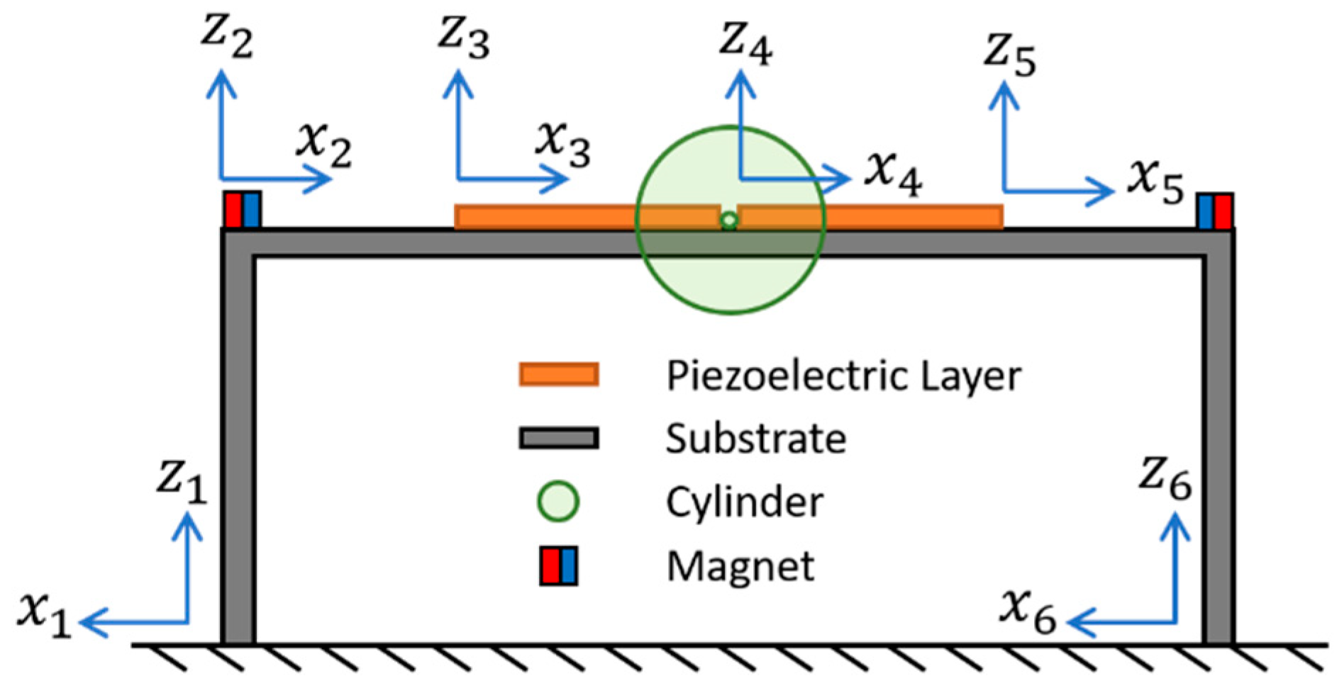
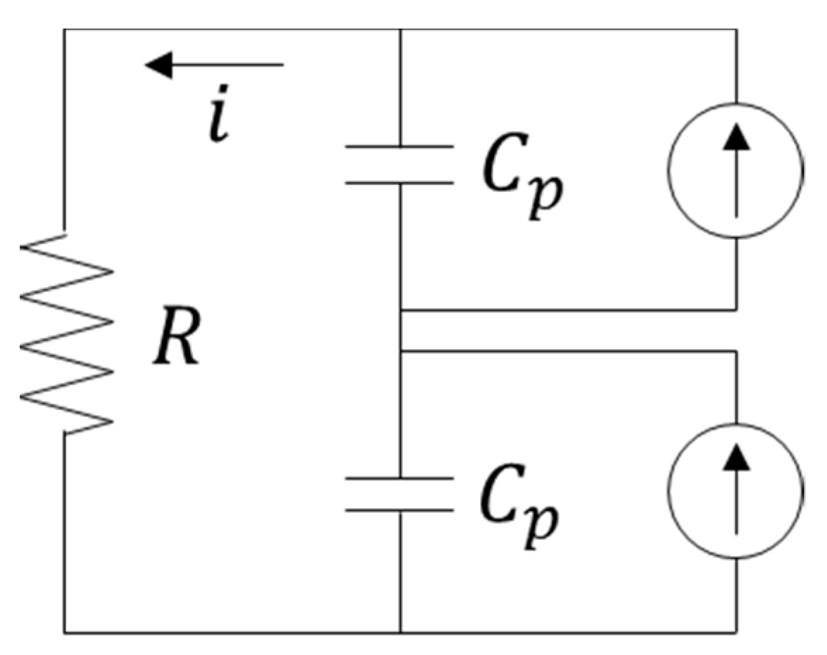
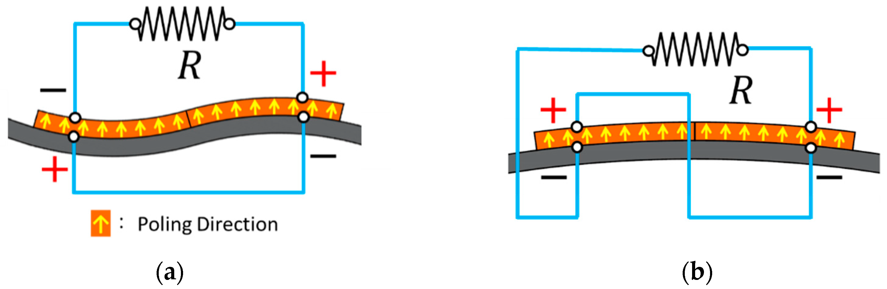
2.1. Modeling of the Proposed Piezoelectric Energy Harvester (PEH)

The U-shaped beam is developed based on Euler-Bernoulli beam theory. While ignoring the damping, the undamped free vibration of the beam can be expressed as:
Y I n 4 w n ( x , t ) x 4 + m n 2 w n ( x , t ) t 2 = 0 n = 1 , , 6
where YI is the bending stiffness of the beam; m is the density of the beam per unit length; w is the transverse displacement and the subscript n denotes the segment number of the beam. The transverse displacement can be further expressed as:
w n ( x n , t ) = r = 1 ϕ r n ( x n ) η r ( t )
where ϕr is the mode shape function; ηr is the temporal function and the subscript r represents the mode. The model shape function can be written as:
ϕ r n ( x n ) = A r n cos ( λ r n L n x n ) + B r n sin ( λ r n L n x n ) + C r n cosh ( λ r n L n x n ) + D r n sinh ( λ r n L n x n )
where Ln is the segment length; Arn, Brn, Crn, and Drn will be determined by the boundary and continuous conditions; λrn is the eigenvalue and its relationship with the undamped natural frequency ωr can be represented as:
ω r = λ r n 2 Y I n m n L n 4
The boundary and continuous conditions of the proposed PEH are listed in Equations (5)–(28):
w r 1 ( 0 , t ) = 0
w r 1 ( 0 , t ) = 0
w r 2 ( 0 , t ) = 0
w r 5 ( L 5 , t ) = 0
w r 6 ( 0 , t ) = 0
w r 6 ( 0 , t ) = 0
w r 1 ( L 1 , t ) = w r 2 ( 0 , t )
Y I 1 w r 1 ( L 1 , t ) = Y I 2 w r 2 ( 0 , t )
w r 2 ( L 2 , t ) = w r 3 ( 0 , t )
Y I 2 w r 2 ( L 2 , t ) = Y I 3 w r 3 ( 0 , t )
w r 3 ( L 3 , t ) = w r 4 ( 0 , t )
Y I 3 w r 3 ( L 3 , t ) = Y I 4 w r 4 ( 0 , t )
Y I 3 w r 3 ( L 3 , t ) = M m i d w ¨ r 3 ( L 3 , t ) + Y I 4 w r 4 ( 0 , t )
w r 4 ( L 4 , t ) = w r 5 ( 0 , t )
w r 4 ( L 2 , t ) = w r 5 ( 0 , t )
Y I 4 w r 4 ( L 4 , t ) = Y I 5 w r 5 ( 0 , t )
w r 5 ( L 5 , t ) = w r 6 ( L 6 , t )
Y I 5 w r 5 ( L 5 , t ) = Y I 6 w r 6 ( L 6 , t )
w r 1 ( L 1 , t ) = w r 6 ( L 6 , t )
Y I 1 w r 1 ( L 1 , t ) + Y I 6 w r 6 ( L 6 , t ) = ( n = 2 5 ( m n L n ) + M t ) w ¨ r 1 ( L 1 , t )
where Mmid is the mass of the cylinder; Mt is the total mass of the cylinder and the magnets attached on the beam. Equations (5)–(28) can be rearranged in the form of matrix as Equation (29):
M [ A r 1 D r 6 ] = [ 0 0 ]
where M is a 24-by-24 matrix. The matrix M can be used to obtain the natural frequencies by making the determinant of M equal to zero. The mode shape function is mass-normalized according to Equation (30).
n = 1 6 m n 0 L n ϕ s n ϕ r n d x + M m i d ϕ s 3 ( L 3 ) ϕ r 3 ( L 3 ) + ( n = 2 5 ( m n L n ) + M t ) ϕ s 1 ( L 1 ) ϕ r 1 ( L 1 ) = δ r s
Finally, the damping, excitation force and electromechanical coupling are considered in the model and the equation of motion of the PEH can be rewritten as:
η ¨ r ( t ) + 2 ζ r ω r η ˙ r ( t ) + ω r 2 η r ( t ) + Q v s v ( t ) = f ( t )
where ζr is the mechanical damping ratio and f is the normalized excitation force. Qvs is the electro-mechanical coupling coefficient and can be represented as:
Q v s = θ s [ d ϕ r 3 ( x ) d x | 0 L 3 + d ϕ r 4 ( x ) d x | 0 L 4 ]       , w h e r e     θ s = E p d 31 b p 4 h p ( h d 2 h c 2 ) ,
Ep, bp, hp, and d31 are the young’s modulus, width, thickness and piezoelectric constant of the piezoelectric layer; hc is the distance from the neutral axis of beam to the bottom surface of the piezoelectric layer; hd is the distance from the neutral axis of beam to the top surface of the piezoelectric layer.
The mode shapes of the proposed PEH under excitations in the horizontal and vertical directions can be found in Figure 3. The mode is defined according to the vibration direction of the beam. The proposed PEH contains a pair of piezoelectric plates, which are connected in series. The equivalent circuit is shown in Figure 4. The equation of the circuit can be represented as:
v ( t ) R + C p s d v ( t ) d t + κ r s η ˙ r = 0
where v is the output voltage, R is the load resistance, Cps is equivalent capacitance of the two piezoelectric plates connected in series and κrs is the electromechanical coupling coefficient, which can be written as:
κ r s = Q v s = θ s [ d ϕ r 3 ( x ) d x | 0 L 3 + d ϕ r 4 ( x ) d x | 0 L 4 ]
It can be found in Figure 3 that different modes result in different bending direction of the piezoelectric plates. Therefore, the two different modes required two different connection configurations to prevent voltage cancellation. The connection configurations are depicted in Figure 5.

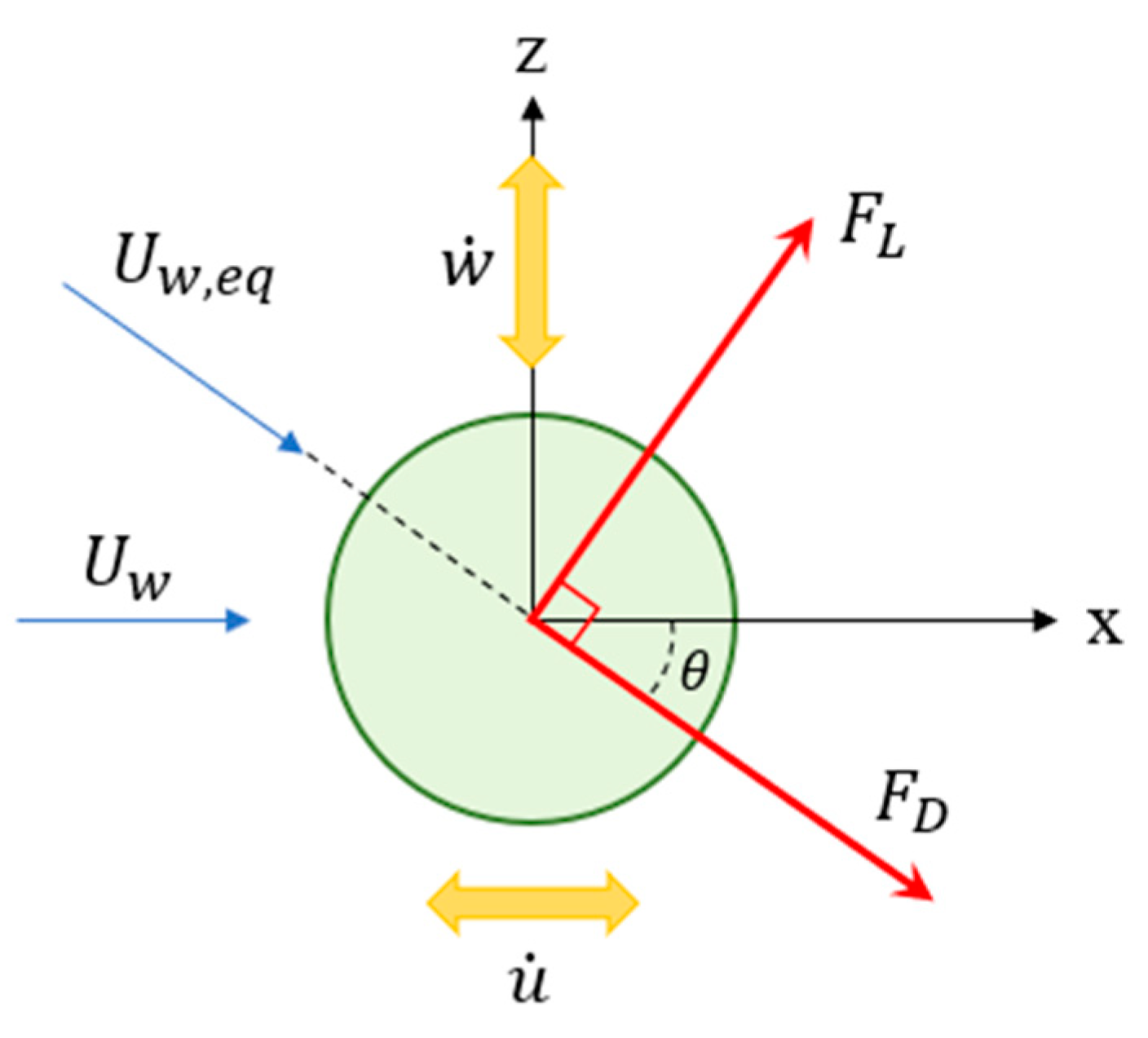
2.2. Vortex-Induced Vibrations
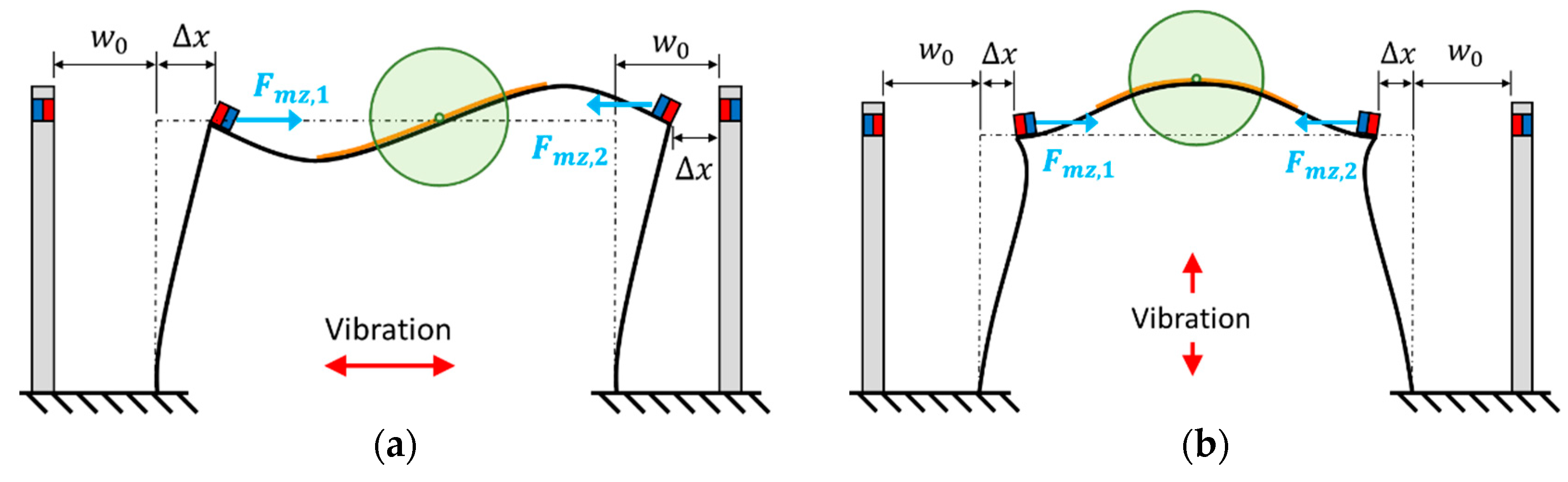
In this study, the wake oscillator was based on the Rayleigh oscillators [30] and can be expressed as:
q ¨ + β ω s ( ( q ˙ ω s ) 2 1 ) q ˙ + ω s 2 q = K D c w ¨
where β is the viscosity coefficient for the structure, K is the coupling coefficient of the vortex and cylinder oscillation. It is noted that β and K are obtained via experimental results. Dc is the diameter of the cylinder and q is the non-dimensional wake variable that describes the lifting in the near-wake region:
q = 2 C L C L 0
where CL is the lifting coefficient of a moving structure and CL0 is that of a stationary structure. ωs is the vortex-shedding frequency and can be expressed as:
ω s = 2 π S t U w D c
where St is Strouhal number, which is related to Reynolds number [31]. Uw is the wind velocity.
The local coordinate of the cylinder in vortex-induced vibrations is depicted in Figure 6. It is shown that when the wind of velocity Uw flows over the cylinder, the cylinder will vibrate in the x direction with velocity of u ˙ and in the y direction with velocity of w ˙ . Therefore, the equivalent wind velocity can be written as:
U w , e q = ( U w u ˙ ) 2 + w ˙ 2
The lift and drag force can then be written as [31]:
F L = 1 2 ρ a U w , e q 2 D c L c C L
F D = 1 2 ρ a U w , e q 2 D c L c C D
where Lc is the length of the cylinder and CD is the drag coefficient of the moving cylinder. In vortex-induced vibrations, the vibration of the cylinder in the horizontal direction is much smaller than that in the vertical direction. Therefore, the displacement of the cylinder in the x direction is ignored and the force applied on the cylinder can be expressed as:
F w z = 1 2 ρ a D c L c [ C L U w , e q ( U w u ˙ ) C D U w , e q w ˙ ]
where ρa is the density of air. Because the velocity of the cylinder is much smaller than the wind speed, Equation (41) is rewritten as:
F w z = 1 2 ρ a D c L c ( C L U w 2 C D U w w ˙ )

2.3. Magnetic Force

In this section, the repulsive force of the cubic magnets is derived. The model was developed based on Furlani’s model [32] of rectangular magnets. The schematic of a pair of cubic magnets is illustrated in Figure 7. Based on the charge model, the surface charge density can be expressed as:
σ i = M i n ^
where the subscript i is used to indicate the magnet number; n is the surface normal; Mi is the magnetization and can be further represented as:
M i = B r i μ 0
where Bri is the residual induction and μ0 is the vacuum permeability.
Consider two cubic magnets that carry charges of Qm1 and Qm2. The potential energy caused by a charge dQmi of magnet i can be expressed as:
d φ m i = d Q m i 4 π 1 R m
where Rm is the distance between the charge and an arbitrary point of a magnet. The total potential energy caused by a surface of magnet i on a charge can be written as:
φ m i = A m i d φ m i d A m i
where Ami is the surface area. The external magnetic field can then be represented as:
H e x t ( x , y , z ) = φ m 1 ( x , y , z )
The magnet flux density is expressed as:
B e x t ( x , y , z ) = μ 0 × H e x t ( x , y , z ) = B x e x t ( x , y , z ) x ^ + B y e x t ( x , y , z ) y ^ + B z e x t ( x , y , z ) z ^
where the x, y, and z components can be written as:
{ B x e x t ( x , y , z ) = μ 0 M 1 4 π i = 1 2 j = 1 2 k = 1 2 ( 1 ) i + j + k × ln [ ( y y j ) + r ] B y e x t ( x , y , z ) = μ 0 M 1 4 π i = 1 2 j = 1 2 k = 1 2 ( 1 ) i + j + k × ln [ ( x x i ) + r ] B z e x t ( x , y , z ) = μ 0 M 1 4 π i = 1 2 j = 1 2 k = 1 2 ( 1 ) i + j + k × tan 1 [ ( x x i ) ( y y j ) ( z z k ) r ]
where
r = ( x x i ) 2 + ( y y j ) 2 + ( z z k ) 2
The variables xi, yj, and zk represent the coordinates of the boundaries of the magnets. The force between magnet 1 and a charge on magnet 2 can be expressed as:
d F m = B e x t ( x , y , z ) d Q m 2
Due to the materials, temperature, humidity etc., the real permeability μ will differ from vacuum permeability μ0. By replacing the vacuum permeability with real permeability, the magnetic force can be expressed as:
F x , y , z = μ M 1 M 2 4 π i = 1 2 j = 1 2 k = 1 2 l = 1 2 m = 1 2 n = 1 2 ( 1 ) i + j + k + l + m + n × f x , y , z ( u , v , w , s )
where
{ f x = v { u u ln ( v + s ) w tan 1 ( u w ) + w tan 1 ( u v w s ) }     + 1 2 u s + w 2 v 2 2 ln ( u + s ) f y = u { v v ln ( u + s ) w tan 1 ( v w ) + w tan 1 ( u v w s ) }     + 1 2 v s + w 2 u 2 2 ln ( v + s ) f z = w s + r e a l ( u w coth 1 ( u s ) + v w coth 1 ( v s ) ) + u v tan 1 ( u v w s )
and
{ u = α + ( 1 ) l L m 2 2 ( 1 ) i L m 1 2 v = β + ( 1 ) m W m 2 2 ( 1 ) j W m 1 2 w = γ + ( 1 ) n H m 2 2 ( 1 ) k H m 1 2 s = u 2 + v 2 + w 2

2.4. Model of the Proposed Non-Linear Bi-Directional PEH

In this section, we will summarize the structural, VIV, and magnet models derived in the previous sections to develop the complete model of the proposed bi-directional PEH. Referring to Equation (31), the external force fwz caused by VIV can be expressed with respect to the mode of the PEH:
f w z ( t ) = { Horizontal:   1 2 ρ a D c L c ( C L U w 2 C D U w ϕ r 1 ( L 1 ) η ˙ r ) ϕ r 1 ( L 1 ) Vertical:   1 2 ρ a D c L c ( C L U w 2 C D U w ϕ r 3 ( L 3 ) η ˙ r ) ϕ r 3 ( L 3 )
The magnetic force is then integrated in the model. The schematics of the proposed PEH with magnets are shown in Figure 8. Two pairs of magnets are installed symmetrically on the PEH to generate repulsive force. The magnetic force can be represented as:
f m z ( t ) = { Horizontal:   ϕ r 1 ( L 1 ) F m z , 1 ( w 0 + ϕ r 1 ( L 1 ) η r ( t ) ) ϕ r 6 ( L 6 ) F m z , 2 ( w 0 ϕ r 6 ( L 6 ) η r ( t ) ) Vertical:   ϕ r 1 ( L 1 ) F m z , 1 ( w 0 + ϕ r 1 ( L 1 ) η r ( t ) ) ϕ r 6 ( L 6 ) F m z , 2 ( w 0 + ϕ r 6 ( L 6 ) η r ( t ) )
Therefore, the complete governing equations of the proposed bi-directional PEH can be represented as:
{ η ¨ r ( t ) + 2 ζ r ω r η ˙ r ( t ) + ω r 2 η r ( t ) + Q v c v ( t ) = f w z ( t ) + f m z ( t ) v c ( t ) R + C p c d v c ( t ) d t + κ r c η ˙ r ( t ) = 0 q ¨ + β ω s ( ( q ˙ ω s ) 2 1 ) q ˙ + ω s 2 q = K D c w ¨ m ( t )
where w ¨ m ( t ) is the acceleration of the cylinder and can be expressed as:
w ¨ m ( t ) = { Horizontal:   w ¨ 1 ( L 1 , t ) Vertical:   w ¨ 3 ( L 3 , t )

3. Experiment

The prototype of the proposed PEH installed in a wind tunnel is shown in Figure 9. The PEH was installed in two different orientations in order to receive wind from two different directions. It can be seen in the supplementary videos 1 and 2 that the vibration direction of the beam structure is perpendicular to the wind direction. The U-shaped structure was a stainless steel (SUS301) beam bent to a shape of U. A pair of macro fiber composite (MFC) patches (M-2807-P2) were attached symmetrically on the main beam of the U-shaped structure. A foam cylinder was installed at the middle of the main beam to induce vortex. The parameters of the prototype are listed in Table 1.
Figure 10 shows the platform for base excitations. The PEH was installed on a shaker (LDS-V406), which was controlled and driven by a vibration controller (UCON VT-9002) and a power amplifier (LDS PA-100E). An accelerometer (PCB 352C66) was used to detect the acceleration of the shaker and send a feedback signal to the controller for closed-loop control. The displacement of the PEH was acquired by a laser displacement sensor (Mti LTS-120-40) and the voltage output was obtained by an oscilloscope (Keysight DSOX4042A). The damping ratio was obtained in the base excitation tests with the acceleration of 0.05 G. The PEH was then tested in a wind tunnel (LonGwin LW-9300S) for VIVs. The schematic of the wind tunnel tests can be seen in Figure 11.

4. Results

In this section, the proposed PEH was firstly examined under base excitations to validate the resonant frequency and fit the damping ratio. The proposed PEH was then investigated in a wind tunnel for VIV tests. The simulated results were compared with the experimental results. Different magnet distances and side-beam lengths were tested to understand their influence on the performance of the PEH.

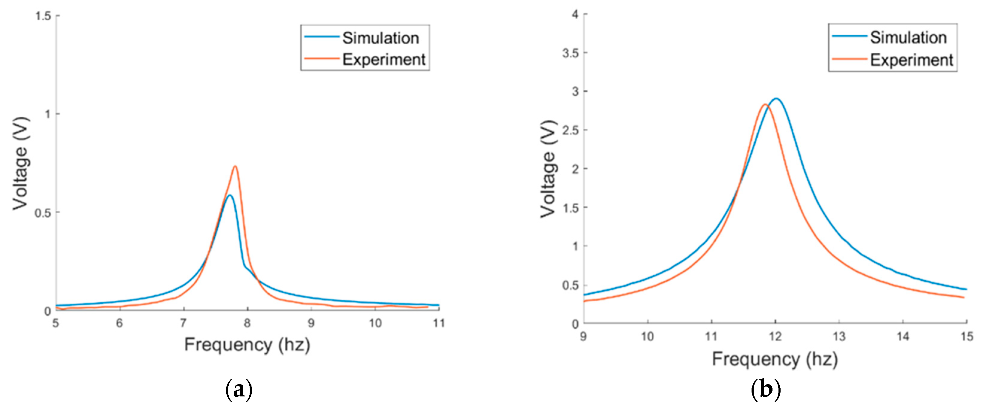
4.1. Proposed PEH under Base Excitation

The prototype of the PEH was first tested under base excitations to verify the resonant frequencies. The displacement in short circuit is depicted in Figure 12. The displacement of the vertical mode was measured at the middle point of the main beam while that of the horizontal mode was measured at the free end of the side beam. It can be seen that the simulated resonant frequencies match the experimental ones well. The errors between the simulated and experimental resonant frequencies of the horizontal and vertical modes were 1.15% and 1.35%, respectively. The damping ratios were obtained by fitting the simulation displacement with the experimental displacement and are arranged in Table 2. The output voltage of the PEH in series connection is shown in Figure 13. A notable difference between the peak voltage of the simulated and experimental results in the horizontal mode may result from the imperfect symmetry of the two MFC patches. Therefore, the bending of the two MFC patches are not identical. Overall, the simulation and experimental results are well matched so the theoretical model will be further utilized for the simulation of the VIV-based PEH.

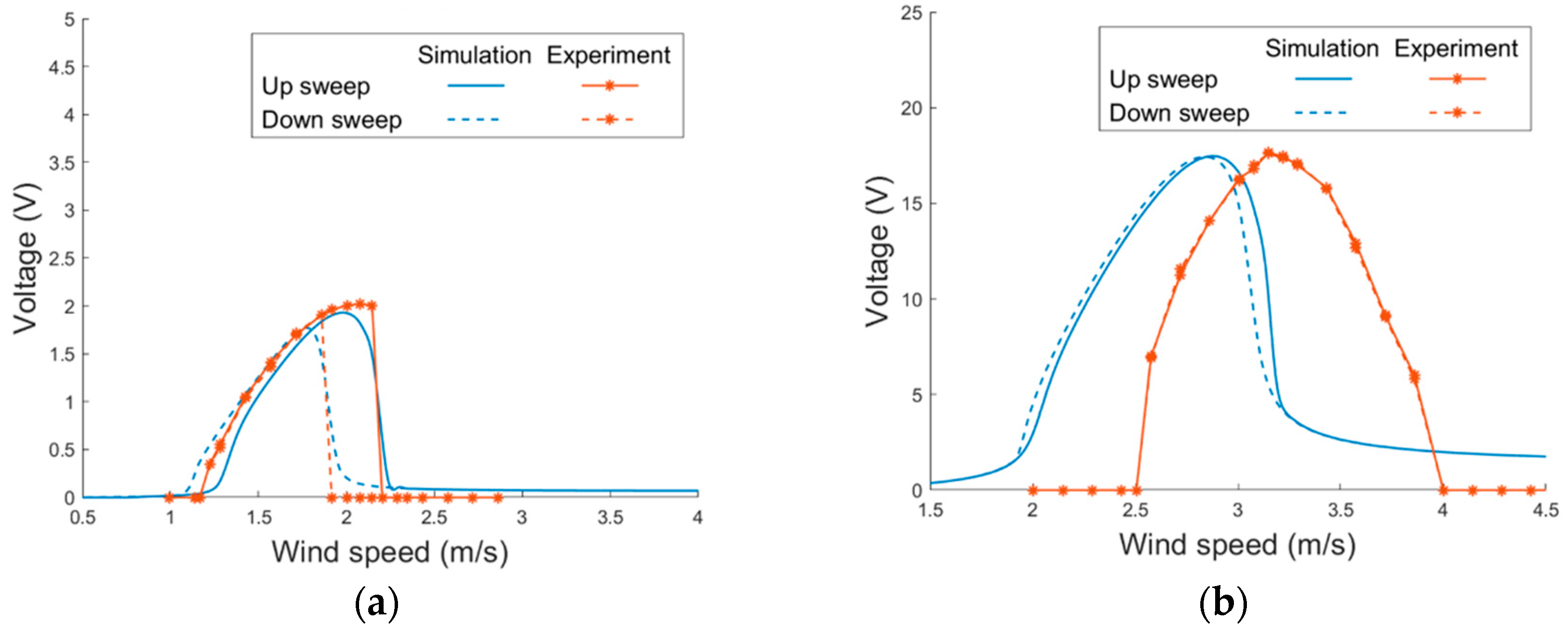
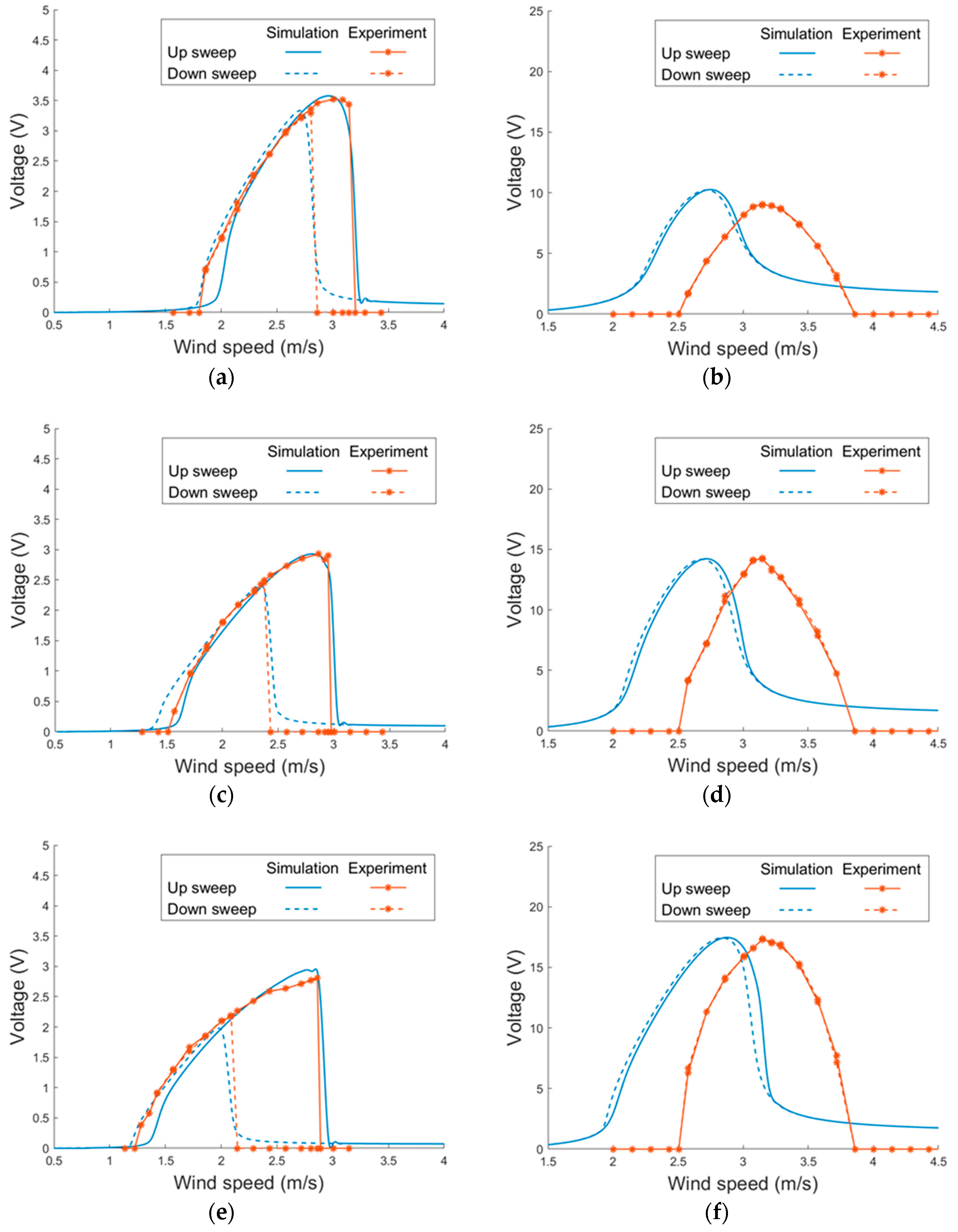
4.2. Proposed PEH under Vortex-Induced Vibrations

The proposed PEH was then examined in the wind tunnel tests. As the system was non-linear, the voltage responses were examined under wind-speed sweeps to see how the nonlinearity influence the responses. The PEH without magnets was first tested. Figure 14 depicts the simulated and experimental voltage responses of the PEH. The viscosity coefficient β and vortex-related coupling coefficient K were obtained via experiments and are shown in Table 3. It can be seen that the model predicts well the responses of the horizontal mode in both up and down sweeps. The model is accurate enough even without taking the geometric non-linearity into consideration. The non-linearity caused by the VIVs demonstrates the hardening effect, which enlarges the lock-in region for up sweeps. On the other hand, the non-linear effect is not notable in the vertical mode. The responses in up and down sweeps are almost identical in both the simulation and experimental results. It can be noted that the experimental lock-in region is shifted to a higher region when compared with the simulation results. The mismatch may result from the deformation of the PEH by the wind pressure, which strengthens the stiffness of the structure and, therefore, increases the lock-in wind speed in experiments.
Figure 15 depicts the voltage responses of the magnet-integrated PEH with different magnet spacing: 17 mm, 19 mm and 21 mm. Three settings of magnet spacing were examined in the simulation and the wind tunnel tests. It can be seen that the experimental results show a similar trend as the simulation results. In all the vertical modes of all the three magnet settings, the width of the lock-in region and the peak voltage of the theoretical and experimental results show a good agreement. In the horizontal mode, the theoretical model predicts the width of the lock-in region and peak voltage under both up and down sweeps well. Stronger non-linearity is noted in the horizontal mode when the magnet gap is smaller.
The experimental results of the PEH with different settings of magnet gap are arranged in Figure 16. It can be noted that the magnetic force improves the lock-in wind speed range and peak voltage in all the three settings of the horizontal mode. It can be seen that the magnet force influences the horizontal mode greatly but has little impact on the vertical mode. That is because the magnets are attached on the end of the side beams, where the displacement is almost zero in the vertical mode. The performance improvement is more significant as the magnet gap is reduced. The PEH demonstrates better performance in up sweeps than down sweeps because of the hardening effect. Moreover, it is noted that the magnet-integrated PEH outperforms that without magnets not only in the up sweeps but also in the down sweeps. In the setting with the gap of 17 mm, which shows the most significant improvement among all settings, the lock-in region is widened by 34.8% and the peak voltage is enhanced by 33.2% in the up sweeps. In the down sweeps, significant improvement of both the peak voltage and lock-in region can still be seen. Overall, adding magnets to the design of the U-shaped PEH improve peak voltage and usable wind-speed region in both up and down sweeps.
Figure 17 shows the simulation and experimental results of the PEH with different side-beam lengths. To change the length of the side beams in experiments, we used the same prototype of the PEH but clamped the side beams at different locations to keep all the parameters unchanged except the side-beam length. The side-beam length has a strong impact on the horizontal mode but only a slight impact on the vertical mode. As the length of the side beam increases, the stiffness of the PEH decreases so the resonant frequency as well as the lock-in wind speed are shifted to a lower region. It can be seen in the simulation and experimental results that lock-in wind speed region of the PEH with the shortest side beams in the horizontal mode during up sweeps is significantly higher than that of the two configurations with longer side beams. The lock-in region in the vertical mode shows no significant difference among the three configurations. However, it can be found that the peak voltage of the vertical mode is improved when the side beams are extended because the mode shape changes. The experimental results of the PEH with different length of the side beams are rearranged in Figure 18. It can be found that the responses in the horizontal mode of all the three configurations show a hardening effect during the wind-speed sweeps. The hardening effect becomes more significant as the length of the side beam increases due to the decrease of the stiffness of the PEH in the horizontal mode.
It can be noted in Figure 16 and Figure 18 that both extending the side beams and reducing the magnet gap can enhance the hardening effect and, therefore, enlarge the lock-in region. However, the side-beam length not only alters the lock-in region but also the peak voltage of both horizontal and vertical modes while the magnet gap only impacts the lock-in region. Moreover, extending the side beams slightly improve the lock-in region in up sweeps. No significant impact on the lock-in region is seen in down sweeps. Nevertheless, reducing the magnet gap demonstrates an improved lock-in region in both up and down sweeps.

5. Conclusions

In this study, we proposed a magnet-integrated VIV-based PEH to achieve bi-directional wind-energy harvesting, as wind comes from various directions in the environment. Magnetic force is introduced to the PEH in order to enhance its performance. The theoretical model is derived based on Euler–Bernoulli beam theory for the structure, Rayleigh oscillators for the VIVs, and the charge model for the magnetic force. A prototype was fabricated and first examined under base excitations to obtain the damping ratio of the PEH. The PEH was then tested in a wind tunnel for VIVs and the VIV-related coupling coefficients were acquired. Finally, the PEH was integrated with magnets attached at the ends of the side beams and examined in VIV tests. Magnet gap and side-beam length were both examined to see their influence on the performance. Wind-speed up and down sweeps were conducted to observe the non-linearity of the proposed PEH. In both up and down sweeps, it was shown that the magnet force enhanced the lock-in region and the peak voltage of the horizontal mode in both up and down sweeps but had little impact on the vertical mode. The PEH with the smallest magnet gap, which was 17 mm, exhibited the best performance among the three settings. On the other hand, when the magnet gap was fixed at 17 mm, shortening the side beams could only enhance the lock-in region of up sweeps but not that of down sweeps. Moreover, the peak voltage of both modes were altered greatly. The study demonstrates that magnetic force can significantly improve the peak voltage and usable wind-speed range in the horizontal mode under both up and down sweeps without influencing the vertical mode.

Supplementary Materials

The following are available online at https://www.mdpi.com/article/10.3390/s21072299/s1. Video S1: Vortex-induced vibration of the PEH in the horizontal mode, Video S2: Vortex-induced vibration of the PEH in the vertical mode.

Author Contributions

Conceptualization, W.-J.S. and Z.-S.W.; methodology, W.-J.S. and Z.-S.W.; software, Z.-S.W.; validation, Z.-S.W.; formal analysis, Z.-S.W.; investigation, W.-J.S. and Z.-S.W.; resources, W.-J.S.; data curation, Z.-S.W.; writing—original draft preparation, W.-J.S.; writing—review and editing, W.-J.S.; visualization, W.-J.S. and Z.-S.W.; supervision, W.-J.S.; project administration, W.-J.S.; funding acquisition, W.-J.S. All authors have read and agreed to the published version of the manuscript.

Funding

This research was funded by the Ministry of Science and Technology of Taiwan, grant number MOST 107-2221-E-002-118-MY3. The APC was funded by the Ministry of Science and Technology of Taiwan.

Institutional Review Board Statement

Not applicable.

Informed Consent Statement

Not applicable.

Data Availability Statement

Not applicable.

Acknowledgments

The authors gratefully acknowledge the financial support of the Ministry of Science and Technology of Taiwan under grant number MOST 107-2221-E-002-118-MY3.

Conflicts of Interest

The authors declare no conflict of interest.

References

  1. Qi, S.; Shuttleworth, R.; Oyadiji, S.O.; Wright, J. Design of a multiresonant beam for broadband piezoelectric energy harvesting. Smart Mater. Struct. 2010, 19, 094009. [Google Scholar] [CrossRef]
  2. Erturk, A.; Renno, J.M.; Inman, D.J. Modeling of Piezoelectric Energy Harvesting from an L-shaped Beam-mass Structure with an Application to UAVs. J. Intell. Mater. Syst. Struct. 2008, 20, 529–544. [Google Scholar] [CrossRef]
  3. Liu, H.; Lee, C.; Kobayashi, T.; Tay, C.J.; Quan, C. Investigation of a MEMS piezoelectric energy harvester system with a frequency-widened-bandwidth mechanism introduced by mechanical stoppers. Smart Mater. Struct. 2012, 21, 035005. [Google Scholar] [CrossRef]
  4. Zhao, D.; Wang, X.; Cheng, Y.; Liu, S.; Wu, Y.; Chai, L.; Liu, Y.; Cheng, Q.; Xiaoman, W.; Yuan, C.; et al. Analysis of single-degree-of-freedom piezoelectric energy harvester with stopper by incremental harmonic balance method. Mater. Res. Express 2018, 5, 055502. [Google Scholar] [CrossRef]
  5. Stanton, S.C.; McGehee, C.C.; Mann, B.P. Nonlinear dynamics for broadband energy harvesting: Investigation of a bistable piezoelectric inertial generator. Phys. D Nonlinear Phenom. 2010, 239, 640–653. [Google Scholar] [CrossRef]
  6. Lan, C.; Qin, W. Enhancing ability of harvesting energy from random vibration by decreasing the potential barrier of bistable harvester. Mech. Syst. Signal Process. 2017, 85, 71–81. [Google Scholar] [CrossRef]
  7. Shih, H.-A.; Su, W.-J. Theoretical analysis and experimental study of a nonlinear U-shaped bi-directional piezoelectric energy harvester. Smart Mater. Struct. 2018, 28, 015017. [Google Scholar] [CrossRef]
  8. Yayla, S.; Ayça, S.; Oruç, M. A case study on piezoelectric energy harvesting with using vortex generator plate modeling for fluids. Renew. Energy 2020, 157, 1243–1253. [Google Scholar] [CrossRef]
  9. Jadidi, P.; Zeinoddini, M. Influence of hard marine fouling on energy harvesting from Vortex-Induced Vibrations of a single-cylinder. Renew. Energy 2020, 152, 516–528. [Google Scholar] [CrossRef]
  10. Gu, M.; Song, B.; Zhang, B.; Mao, Z.; Tian, W. The effects of submergence depth on Vortex-Induced Vibration (VIV) and energy harvesting of a circular cylinder. Renew. Energy 2020, 151, 931–945. [Google Scholar] [CrossRef]
  11. Sun, H.; Bernitsas, M.M.; Turkol, M. Adaptive harnessing damping in hydrokinetic energy conversion by two rough tandem-cylinders using flow-induced vibrations. Renew. Energy 2020, 149, 828–860. [Google Scholar] [CrossRef]
  12. Tan, T.; Hu, X.; Yan, Z.; Zhang, W. Enhanced low-velocity wind energy harvesting from transverse galloping with super capacitor. Energy 2019, 187, 115915. [Google Scholar] [CrossRef]
  13. Zhao, L.; Tang, L.; Yang, Y. Synchronized charge extraction in galloping piezoelectric energy harvesting. J. Intell. Mater. Syst. Struct. 2016, 27, 453–468. [Google Scholar] [CrossRef]
  14. Yang, K.; Wang, J.; Yurchenko, D. A double-beam piezo-magneto-elastic wind energy harvester for improving the galloping-based energy harvesting. Appl. Phys. Lett. 2019, 115, 193901. [Google Scholar] [CrossRef]
  15. Petrini, F.; Gkoumas, K. Piezoelectric energy harvesting from vortex shedding and galloping induced vibrations inside HVAC ducts. Energy Build. 2018, 158, 371–383. [Google Scholar] [CrossRef]
  16. Barrero-Gil, A.; Alonso, G.; Sanz-Andres, A. Energy harvesting from transverse galloping. J. Sound Vib. 2010, 329, 2873–2883. [Google Scholar] [CrossRef]
  17. Orrego, S.; Shoele, K.; Ruas, A.; Doran, K.; Caggiano, B.; Mittal, R.; Kang, S.H. Harvesting ambient wind energy with an inverted piezoelectric flag. Appl. Energy 2017, 194, 212–222. [Google Scholar] [CrossRef]
  18. Zhou, Z.; Qin, W.; Zhu, P.; Du, W.; Deng, W.; Pan, J. Scavenging wind energy by a dynamic-stable flutter energy harvester with rectangular wing. Appl. Phys. Lett. 2019, 114, 243902. [Google Scholar] [CrossRef]
  19. Li, K.; Yang, Z.; Gu, Y.; He, S.; Zhou, S. Nonlinear magnetic-coupled flutter-based aeroelastic energy harvester: Modeling, simulation and experimental verification. Smart Mater. Struct. 2018, 28, 015020. [Google Scholar] [CrossRef]
  20. Bryant, M.; Garcia, E. Modeling and Testing of a Novel Aeroelastic Flutter Energy Harvester. J. Vib. Acoust. 2011, 133, 011010. [Google Scholar] [CrossRef]
  21. Sun, W.; Guo, F.; Seok, J. Development of a novel vibro-wind galloping energy harvester with high power density incorporated with a nested bluff-body structure. Energy Convers. Manag. 2019, 197, 111880. [Google Scholar] [CrossRef]
  22. Demori, M.; Ferrari, M.; Bonzanini, A.; Poesio, P.; Ferrari, V. Autonomous Sensors Powered by Energy Harvesting from von Karman Vortices in Airflow. Sensors 2017, 17, 2100. [Google Scholar] [CrossRef] [PubMed]
  23. Alhadidi, A.H.; Daqaq, M.F. A broadband bi-stable flow energy harvester based on the wake-galloping phenomenon. Appl. Phys. Lett. 2016, 109, 033904. [Google Scholar] [CrossRef]
  24. Jung, H.-J.; Lee, S.-W. The experimental validation of a new energy harvesting system based on the wake galloping phenomenon. Smart Mater. Struct. 2011, 20, 055022. [Google Scholar] [CrossRef]
  25. Akaydin, H.D.; Elvin, N.; Andreopoulos, Y. The performance of a self-excited fluidic energy harvester. Smart Mater. Struct. 2012, 21. [Google Scholar] [CrossRef]
  26. Zhou, S.; Wang, J. Dual serial vortex-induced energy harvesting system for enhanced energy harvesting. AIP Adv. 2018, 8, 075221. [Google Scholar] [CrossRef]
  27. Zhang, L.; Abdelkefi, A.; Dai, H.; Naseer, R.; Wang, L. Design and experimental analysis of broadband energy harvesting from vortex-induced vibrations. J. Sound Vib. 2017, 408, 210–219. [Google Scholar] [CrossRef]
  28. Wang, J.; Hu, G.; Su, Z.; Li, G.; Zhao, W.; Tang, L.; Zhao, L. A cross-coupled dual-beam for multi-directional energy harvesting from vortex induced vibrations. Smart Mater. Struct. 2019, 28, 12LT02. [Google Scholar] [CrossRef]
  29. Su, W.-J.; Lin, W.-Y. Design and analysis of a vortex-induced bi-directional piezoelectric energy harvester. Int. J. Mech. Sci. 2020, 173, 105457. [Google Scholar] [CrossRef]
  30. Zanganeh, H.; Srinil, N. Three-dimensional VIV prediction model for a long flexible cylinder with axial dynamics and mean drag magnifications. J. Fluids Struct. 2016, 66, 127–146. [Google Scholar] [CrossRef]
  31. Blevins, R.D. Flow-Induced Vibration; Van Nostrand Reinhold Co.: New York, NY, USA, 1977. [Google Scholar]
  32. Furlani, E.P. Permanent Magnet and Electromechanical Devices: Materials, Analysis, and Applications; Academic Press: San Diego, CA, USA, 2001. [Google Scholar]
Figure 1. Schematic of the proposed bi-directional vortex-induced vibration (VIV) piezoelectric energy harvester (PEH).
Sensors 21 02299 g001
Figure 2. The local coordinates of the bi-directional PEH with magnetic interaction.
Sensors 21 02299 g002
Figure 3. Mode shapes of the proposed bi-directional PEH under VIVs: (a) horizontal mode (b) vertical mode.
Sensors 21 02299 g003
Figure 4. The equivalent circuit of the proposed PEH.
Sensors 21 02299 g004
Figure 5. Circuit connections of the piezoelectric patches for (a) horizontal mode (b) vertical mode.
Sensors 21 02299 g005
Figure 6. The local coordinate of the cylinder.
Sensors 21 02299 g006
Figure 7. Schematic of a pair of cubic magnets.
Sensors 21 02299 g007
Figure 8. Schematics of the PEH with magnets in (a) the horizontal mode, (b) the vertical mode.
Sensors 21 02299 g008
Figure 9. Setup of the proposed PEH installed in the wind tunnel for (a) horizontal mode, and (b) vertical mode.
Sensors 21 02299 g009
Figure 10. Schematic of the platform for base-excitation tests.
Sensors 21 02299 g010
Figure 11. Schematic of the wind tunnel for VIV tests.
Sensors 21 02299 g011
Figure 12. Displacement responses in short circuit under base excitations in (a) horizontal mode, (b) vertical mode.
Sensors 21 02299 g012
Figure 13. Voltage responses under base excitations in (a) horizontal mode, (b) vertical mode.
Sensors 21 02299 g013
Figure 14. Voltage responses of the proposed PEH without magnets under VIVs in (a) horizontal mode (b) vertical mode.
Sensors 21 02299 g014
Figure 15. Voltage responses of the proposed PEH with different magnet spacing under VIVs (side-beam length = 40 mm). (a) 17 mm, horizontal (b) 17 mm, vertical (c) 19 mm, horizontal (d) 19 mm, vertical, (e) 21 mm, horizontal, (f) 21 mm, vertical.
Sensors 21 02299 g015
Figure 16. Experimental voltage responses of the proposed PEH with different magnet gaps under VIVs (side-beam length = 40 mm). (a) horizontal mode (b) vertical mode.
Sensors 21 02299 g016
Figure 17. Voltage responses of the proposed PEH with different side-beam lengths under VIVs. (magnet gap = 17 mm) (a) 30 mm, horizontal (b) 30 mm, vertical (c) 35 mm, horizontal (d) 35 mm, vertical, (e) 40 mm, horizontal, (f) 40 mm, vertical.
Sensors 21 02299 g017
Figure 18. Experimental voltage responses of the proposed PEH with side-beam lengths under VIVs (magnet gap = 17 mm). (a) horizontal mode (b) vertical mode.
Sensors 21 02299 g018
Table 1. Parameters of the prototype.
ParametersSymbolValue
Length of the main beam 130 mm
Length of the side beam 40 mm
Length of the magnet on the PEHLmag,13 mm
Length of the magnet on the baseLmag,24 mm
Length of the epoxy layerLex33.5 mm
Length of the macro fiber composite (MFC) patchLp33.5 mm
Length of the cylinderLc200 mm
Young’s modulus of the substrateYs178 GPa
Young’s modulus of the epoxyYex27 MPa
Young’s modulus of the MFC patchYe30.336 GPa
Thickness of the substratehs0.07 mm
Thickness of the epoxy layerhex0.02 mm
Thickness of the MFC patchhp0.3 mm
Width of the substratebs12.7 mm
Width of the epoxy layerbex6.4 mm
Width of the MFC patchbp6.4 mm
Density of the substrateρs7800 kg/m3
Density of the epoxyρe1200 kg/m3
Density of the MFC patchρp5440 kg/m3
Weight of the magnet on the PEHMmag0.255 g
MagnetizationBr1.32 T
Relative permeabilityμr1.2
Permeabilityμ04π × 10−7 N∙A−2
Diameter of the cylinderDc40 mm
Weight of the cylinderMc2.7 g
Weight of the stickMstick0.3 g
Capacitance (MFC)Cp21.2 nF
Piezoelectric constant (MFC)d31−250 pm/V
Load resistance (base excitation)R500 kΩ
Load resistance (VIVs)R1 MΩ
Table 2. Damping ratio.
ModeDamping Ratio
horizontal0.0182
vertical0.0326
Table 3. Fitted parameters of the proposed PEH under VIVs.
ModeKβ
horizontal17.70.12
vertical170.24
Publisher’s Note: MDPI stays neutral with regard to jurisdictional claims in published maps and institutional affiliations.

