
Bandwidth Optimization of a Textile PIFA with DGS Using Characteristic Mode Analysis

 ,
,  ,
,  ,
,
Abstract
:1. Introduction
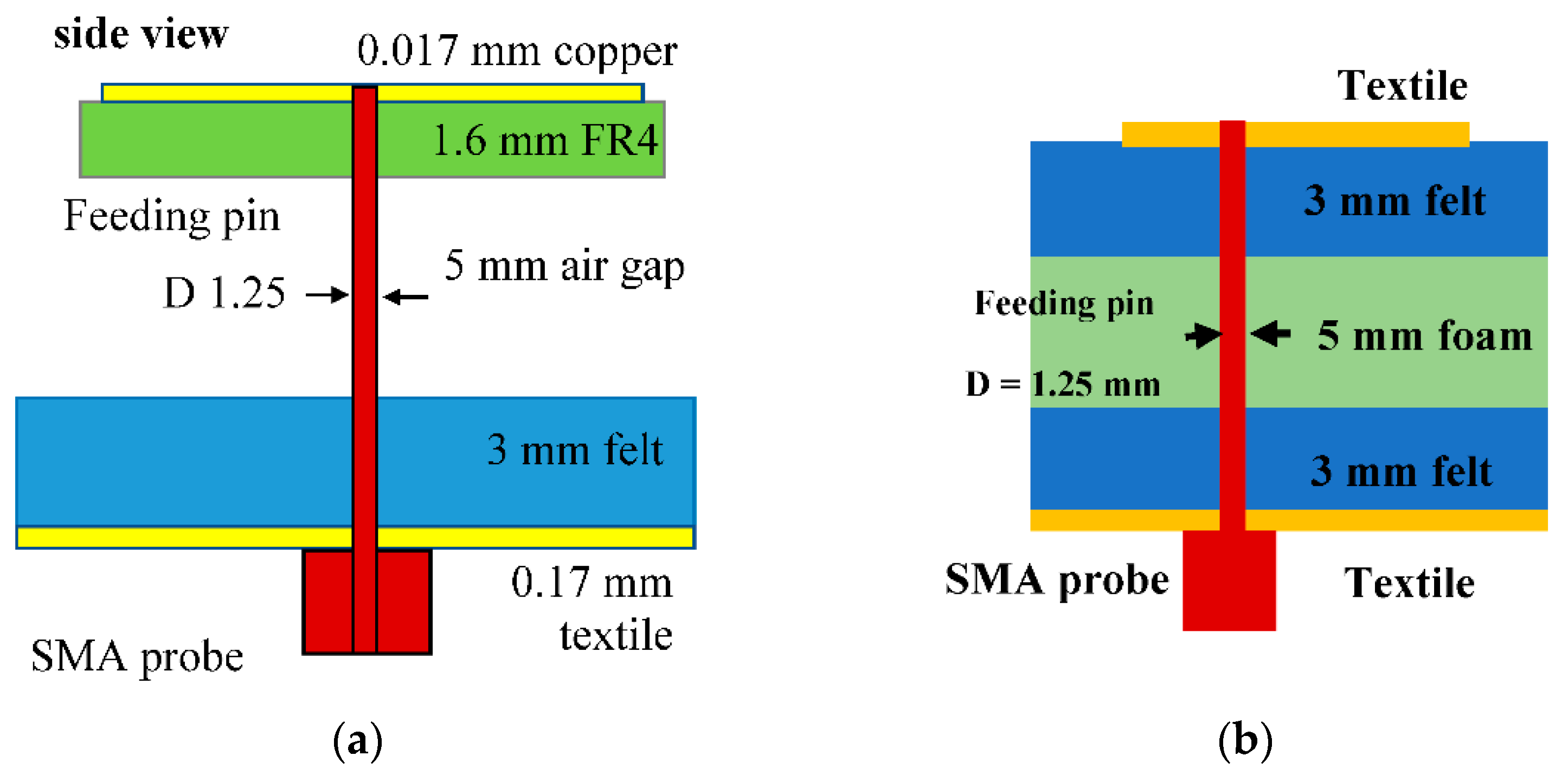
2. Antenna Design
- a 50 × 25 mm2 ground plane made using a 0.17 mm thick Shieldlt conductive textile (with conductivity, σ = 1.18 × 10⁵ S/m),
- a 3 mm thick felt substrate (εr = 1.3, tanδ = 0.044),
- a 5 mm air gap,
- a 1.6 mm thick FR4 substrate (εr = 4.3, tanδ = 0.044),
- and a patch built using a 0.17 mm thick copper conductor.
3. Optimization Procedure and Results
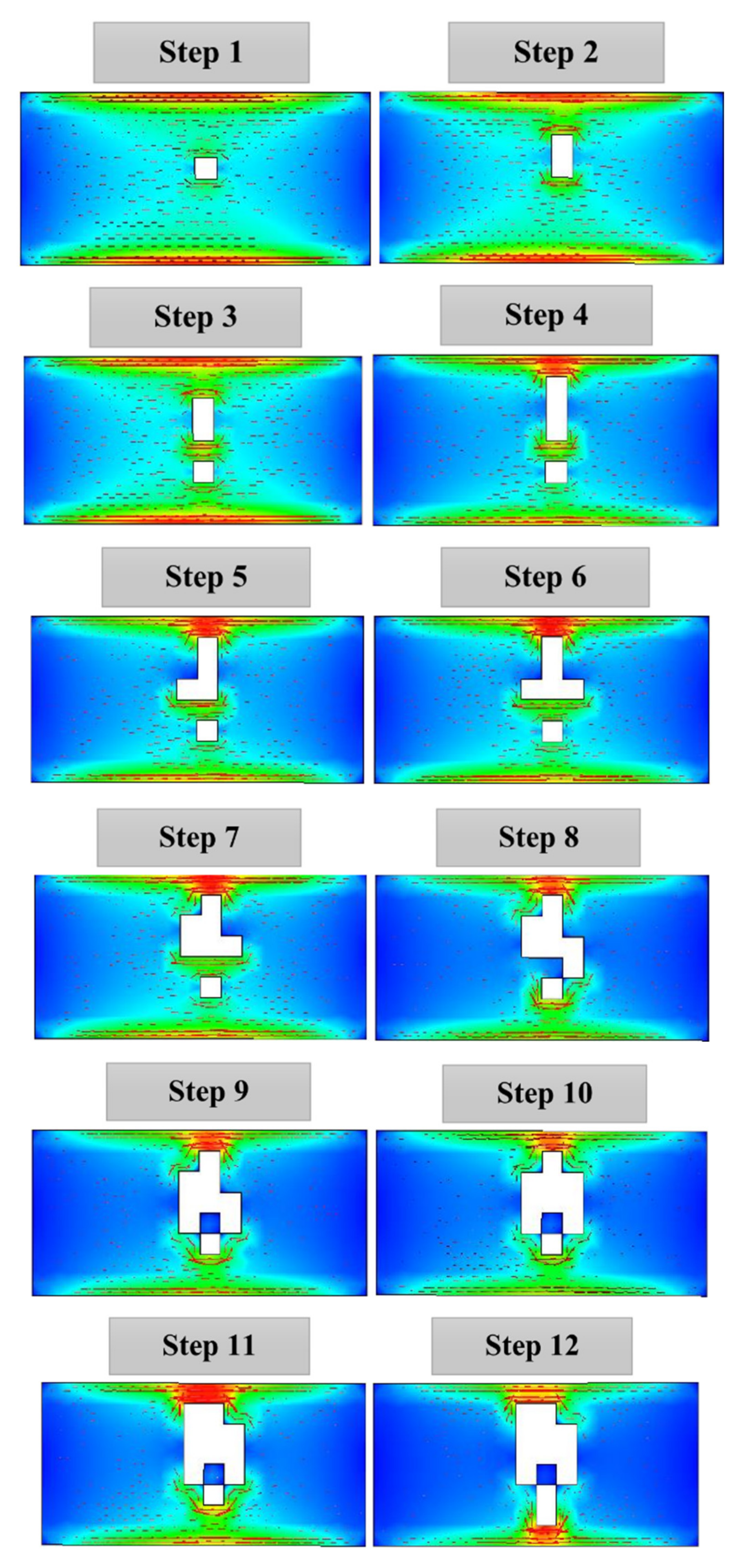
3.1. DGS Design and Optimization
- First, the PEC ground plane is analyzed alone without the rest of the antenna parts.
- Next, the modal significance result based on the dimensions of the ground plane is assessed to identify the dominant modes and their frequencies using CMA.
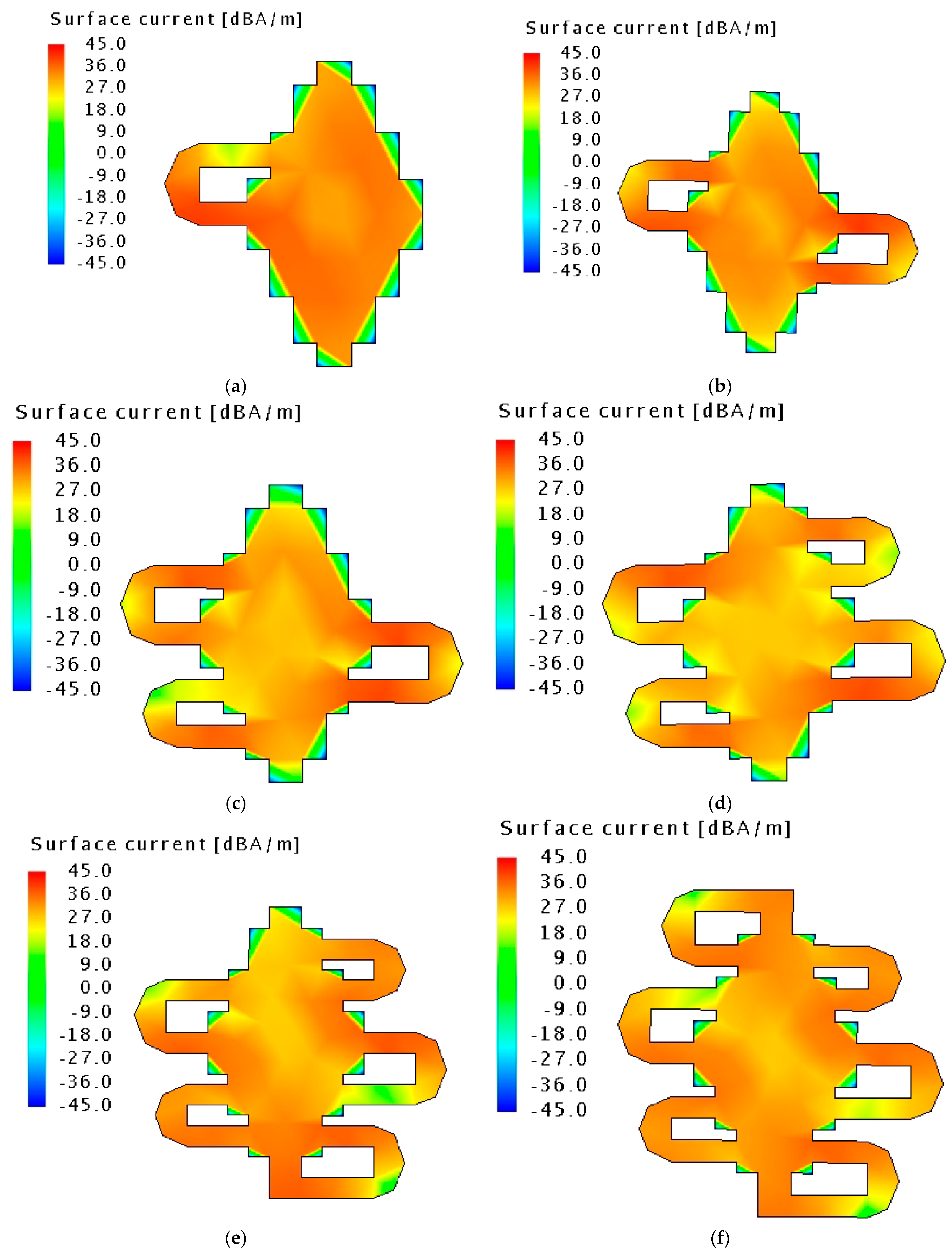
- The eigen currents are then generated on the surface of the ground plane using CMA to identify the areas having the lowest values of currents. The etching of the DGS is initialized at these locations.
- Finally, slots are then gradually inserted until the desired resonant frequency is achieved. This is observed from the modal significance curves being significant (>0.7) at the desired operating frequency. This enables the estimation of the final structure of the DGS.
3.2. Patch Structure
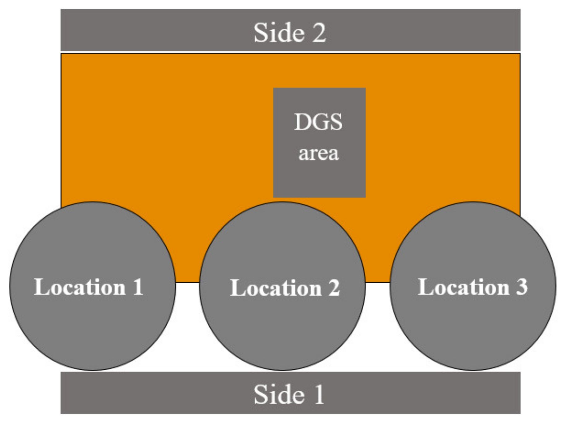
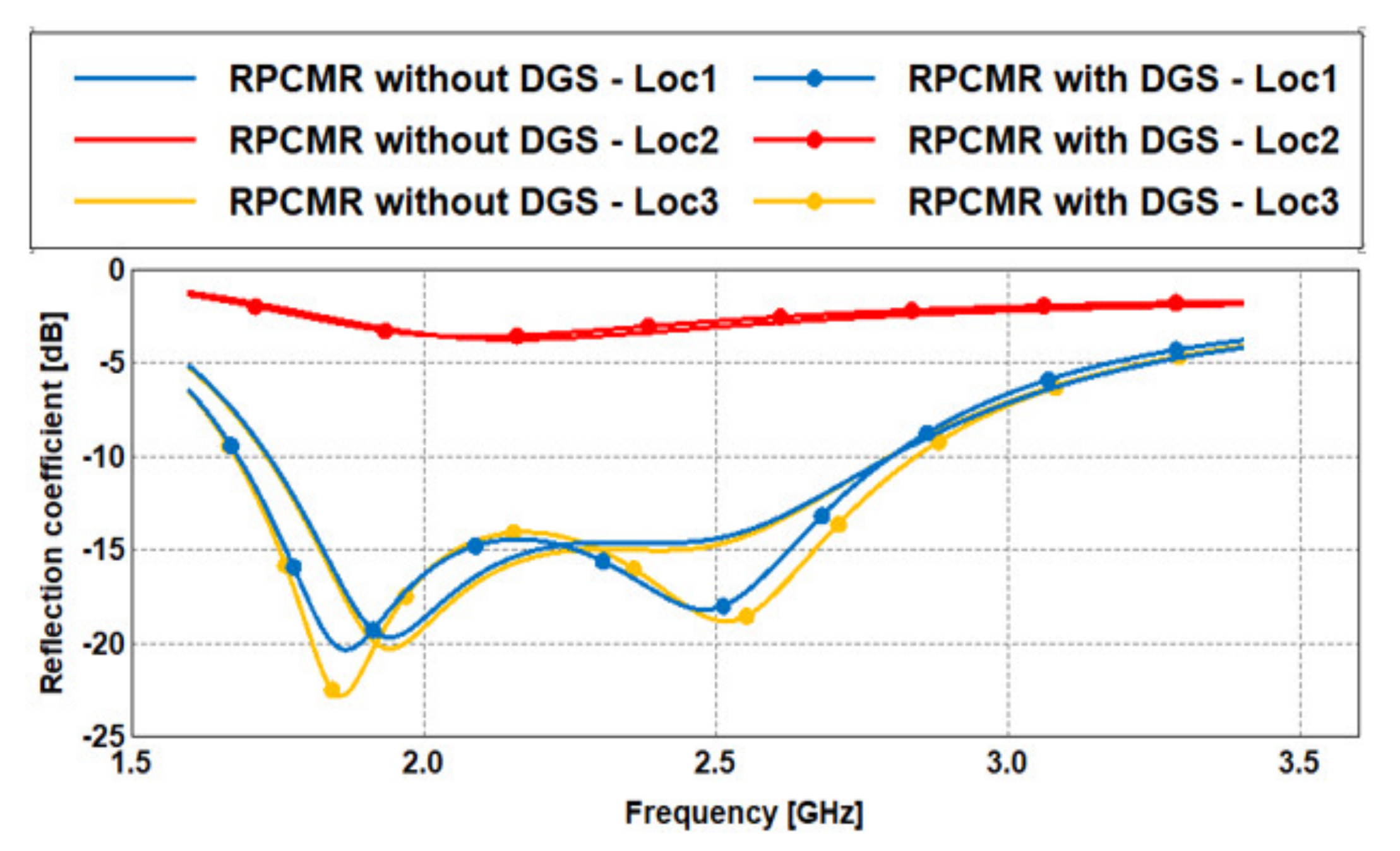
3.3. Optimal Ground Location
4. Antenna on Body Evaluation
5. Prototype and Measurements
6. Conclusions
Author Contributions
Funding
Institutional Review Board Statement
Informed Consent Statement
Conflicts of Interest
References
- Sabban, A. Small New Wearable Antennas for IOT, Medical and Sport Applications. In Proceedings of the 2019 13th European Conference on Antennas and Propagation (EuCAP), Krakow, Poland, 31 March–5 April 2019; pp. 1–5. [Google Scholar]
- Li, S.; Li, J. Smart Patch Wearable Antenna on Jeans Textile for Body Wireless Communication. In Proceedings of the 2018 12th International Symposium on Antennas, Propagation and EM Theory (ISAPE), Hangzhou, China, 3–6 December 2018; pp. 1–4. [Google Scholar] [CrossRef]
- Alsharif, F.; Kurnaz, C. Wearable Microstrip Patch Ultra-Wide Band Antenna for Breast Cancer Detection. In Proceedings of the 2018 41st International Conference on Telecommunications and Signal Processing (TSP), Athens, Greece, 4–6 July 2018; pp. 1–5. [Google Scholar] [CrossRef]
- Almangour, Y.; Sabouni, A. Flexible Antenna for Wearable Devices at Wi-Fi frequency band. In Proceedings of the 2018 International Applied Computational Electromagnetics Society Symposium—China (ACES), Beijing, China, 29 July–1 August 2018; pp. 1–2. [Google Scholar] [CrossRef]
- Yan, S.; Volskiy, V.; Vandenbosch, G.A.E. Compact Dual-Band Textile PIFA for 433-MHz/2.4-GHz ISM Bands. IEEE Antennas Wirel. Propag. Lett. 2017, 16, 2436–2439. [Google Scholar] [CrossRef]
- Agneessens, S.; Rogier, H. Compact Half Diamond Dual-Band Textile HMSIW On-Body Antenna. IEEE Trans. Antennas Propag. 2014, 62, 2374–2381. [Google Scholar] [CrossRef] [Green Version]
- Yan, S.; Soh, P.J.; Vandenbosch, G.A.E. Compact All-Textile Dual-Band Antenna Loaded with Metamaterial-Inspired Structure. IEEE Antennas Wirel. Propag. Lett. 2015, 14, 1486–1489. [Google Scholar] [CrossRef]
- Yan, S.; Soh, P.J.; Vandenbosch, G.A.E. Wearable Dual-Band Magneto-Electric Dipole Antenna for WBAN/WLAN Applications. IEEE Trans. Antennas Propag. 2015, 63, 4165–4169. [Google Scholar] [CrossRef]
- Sanz-Izquierdo, B.; Batchelor, J.C.; Sobhy, M.I. Button Antenna on Textiles for Wireless Local Area Network on Body Applications. IET Microw. Antennas Propag. 2010, 4, 1980–1987. [Google Scholar] [CrossRef] [Green Version]
- Yang, X.; Liu, Y.; Gong, S. Design of a Wideband Omnidirectional Antenna with Characteristic Mode Analysis. IEEE Antennas Wirel. Propag. Lett. 2018, 17, 993–997. [Google Scholar] [CrossRef]
- Bauer, J.E.; Gentner, P.K. Characteristic Mode Analysis of a Circular Polarised Rectangular Patch Antenna. In Proceedings of the 2019 13th European Conference on Antennas and Propagation (EuCAP), Krakow, Poland, 29 July–1 August 2019; pp. 1–3. [Google Scholar]
- Mahlaoui, Z.; Antonino-Daviu, E.; Latif, A.; Ferrando-Bataller, M. From the Characteristic Modes Analysis to the Design of a Radiation Pattern Reconfigurable Antenna. In Proceedings of the 2019 13th European Conference on Antennas and Propagation (EuCAP), Krakow, Poland, 29 July–1 August 2019; pp. 1–4. [Google Scholar]
- Phung, Q.Q.; Nguyen, T.H.; Michishita, N.; Sato, H.; Koyanagi, Y.; Morishita, H. Characteristic Mode Analysis of U-Shaped Folded Dipole Antenna for WiMAX. In Proceedings of the 2019 International Workshop on Antenna Technology (iWAT), Miami, FL, USA, 3–6 March 2019; pp. 105–107. [Google Scholar] [CrossRef]
- Garbacz, R.; Turpin, R. A Generalized Expansion for Radiated and Scattered Fields. IEEE Trans. Antennas Propag. 1971, 19, 348–358. [Google Scholar] [CrossRef] [Green Version]
- Harrington, R.; Mautz, J. Computation of Characteristic Modes for Conducting Bodies. IEEE Trans. Antennas Propag. 1971, 19, 629–639. [Google Scholar] [CrossRef]
- Harrington, R.; Mautz, J. Theory of Characteristic Modes for Conducting Bodies. IEEE Trans. Antennas Propag. 1971, 19, 622–628. [Google Scholar] [CrossRef]
- Dixit, M.; Tripathi, M.G.S. CPW-fed Monopole Printed Antenna using Staircase shaped Defected Ground Structure for Wireless Application. In Proceedings of the 2018 IEEE International Students’ Conference on Electrical, Electronics and Computer Science (SCEECS), Bhopal, India, 24–25 February 2018; pp. 1–4. [Google Scholar] [CrossRef]
- Ma, W. A Microstrip Patch Antenna Design with Harmonic Rejection Using Defected Ground Structure. In Proceedings of the 2019 IEEE MTT-S International Wireless Symposium (IWS), Guangzhou, China, 19–22 May 2019; pp. 1–3. [Google Scholar] [CrossRef]
- Ponchak, G.E. Dual of Defected Ground Structure for Coplanar Stripline. IEEE Microw. Wirel. Compon. Lett. 2018, 28, 105–107. [Google Scholar] [CrossRef]
- Islam, M.S.; Ibrahimy, M.I.; Motakabber, S.M.A.; Hossain, A.K.M.Z. A Rectangular Inset-Fed Patch Antenna with Defected Ground Structure for ISM Band. In Proceedings of the 2018 7th International Conference on Computer and Communication Engineering (ICCCE), Kuala Lumpur, Malaysia, 19–20 September 2018; pp. 104–108. [Google Scholar] [CrossRef]
- Guha, D.; Biswas, S.; Kumar, C. Printed Antenna Designs Using Defected Ground Structures: A Review of Fundamentals and State-of-the-Art Developments. Forum Electromagn. Res. Methods Appl. Technol. (FERMAT) 2014, 2, 1–13. [Google Scholar]
- Yan, S.; Vandenbosch, G.A.E. Design of Wideband Wearable Antenna using Characteristic Mode Analysis. In Proceedings of the 2019 URSI Asia-Pacific Radio Science Conference (AP-RASC), New Delhi, India, 9–15 March 2019; pp. 1–4. [Google Scholar] [CrossRef]
- Zaidi, N.I.; Ali, M.T.; Rahman, N.H.A.; Nordin, M.S.A.; Shah, A.A.S.A.; Yahya, M.F.; Yon, H. Analysis of Different Feeding Techniques on Textile Antenna. In Proceedings of the 2019 International Symposium on Antennas and Propagation (ISAP), Xi’an, China, 27–30 October 2019; pp. 1–3. [Google Scholar]
- Cibin, C.; Leuchtmann, P.; Gimersky, M.; Vahldieck, R.; Moscibroda, S. Modified E-shaped PIFA antenna for wearable systems. In Proceedings of the 2004 URSI International Symposium on Electromagnetic Theory (EMTS), Pisa, Italy, 23–27 May 2004. [Google Scholar]
- Rahman, M.M.; Islam, M.S.; Wong, H.Y.; Alam, T.; Islam, M.T. Performance Analysis of a Defected Ground-Structured Antenna Loaded with Stub-Slot for 5G Communication. J. Sci. Technol. Sens. Biosens. 2019, 19, 2634. [Google Scholar] [CrossRef] [PubMed] [Green Version]
- Alayesh, M.A. Analysis and Design of Reconfigurable Multi-Band Stacked Microstrip Patch Antennas (MSAs) for Wireless Applications. In Electrical & Computer Engineering Department; The University of New Mexico: Albuquerque, NM, USA, 2007. [Google Scholar]
- Kaschel, H.; Ahumada, C. Design of Rectangular Microstrip Patch Antenna for 2.4 GHz applied a WBAN. In Proceedings of the IEEE International Conference on Automation/XXIII Congress of the Chilean Association of Automatic Control (ICA-ACCA), Concepcion, Chile, 17–19 October 2018; pp. 1–6. [Google Scholar] [CrossRef]
- Miralles, E.; Andreu, C.; Cabedo-Fabrés, M.; Ferrando-Bataller, M.; Monserrat, J. UWB On-Body Slotted Patch Antennas for In-Body Communications. In Proceedings of the 11th European Conference on Antennas and Propagation (EUCAP), Paris, France, 19–24 March 2017. [Google Scholar] [CrossRef]
- Gupta, A.; Kansal, A.; Chawla, P. Design of a Compact Dual-Band Antenna for On-/Off Body Communication. IETE J. Res. 2020, 1–9. [Google Scholar] [CrossRef]
- Carcamo, H.K.; Olivares, C.L.; Vera, C.A. Numerical Finite Difference Method of Electric Field Generated to determine the SAR Generated in a Microstrip Antenna Type Applied to a WBAN. IEEE Lat. Am. Trans. 2016, 14, 2921–2926. [Google Scholar] [CrossRef]
- Bhattacharjee, S.; Maity, S.; Chaudhuri, S.R.B.; Mitra, M. A Compact Dual-Band Dual-Polarized Omnidirectional Antenna for On-Body Applications. IEEE Trans. Antennas Propag. 2019, 67, 5044–5053. [Google Scholar] [CrossRef]
- Bhattacharjee, S.; Midya, M.; Chaudhuri, S.R.B.; Mitra, M. A Ground Radiating Antenna for On-Body Communication. In Proceedings of the IEEE Applied Electromagnetics Conference (AEMC), Miami, Aurangabad, India, 19–22 December 2017. [Google Scholar] [CrossRef]
- Suraya, A.N.; Sabapathy, T.; Jusoh, M.; Ghazali, N.H.; Osman, M.N.; Ismail, S.; Awal, M.R. Wearable Antenna Gain Enhancement Using Reactive Impedance Substrate. Indones. J. Electr. Eng. Comput. Sci. 2019, 13, 708–712. [Google Scholar] [CrossRef]
- Mao, C.X.; Zhou, Y.; Wu, Y.; Soewardiman, H.; Werner, D.H.; Jur, J.S. Low-Profile Strip-Loaded Textile Antenna with Enhanced Bandwidth and Isolation for Full-Duplex Wearable Applications. IEEE Trans. Antennas Propag. 2020, 68, 6527–6537. [Google Scholar] [CrossRef]
- Chin, K.-S.; Wu, C.-S.; Shen, C.-L.; Tsai, K.-C. Designs of Textile Antenna Arrays for Smart Clothing Applications. Autex Res. J. 2018, 18, 295–307. [Google Scholar] [CrossRef] [Green Version]


| Parameter | Value (mm) | Parameter | Value (mm) |
|---|---|---|---|
| W1 | 9.3 | L4 | 1.86 |
| W2 | 6.82 | L5 | 1.86 |
| W3 | 4.34 | L6 | 1.24 |
| W4 | 6.25 | L7 | 1.24 |
| L1 | 3.72 | L8 | 3.125 |
| L2 | 2.48 | L9 | 3.125 |
| L3 | 2.48 | L10 | 3.125 |
| Location | Resonant Frequency (GHz) | Reflection Coefficient (dB) | Realized Gain (dB) | Bandwidth (GHz) | Efficiency % | |||||
|---|---|---|---|---|---|---|---|---|---|---|
| Without DGS | With DGS | Without DGS | With DGS | Without DGS | With DGS | Without DGS | With DGS | Without DGS | With DGS | |
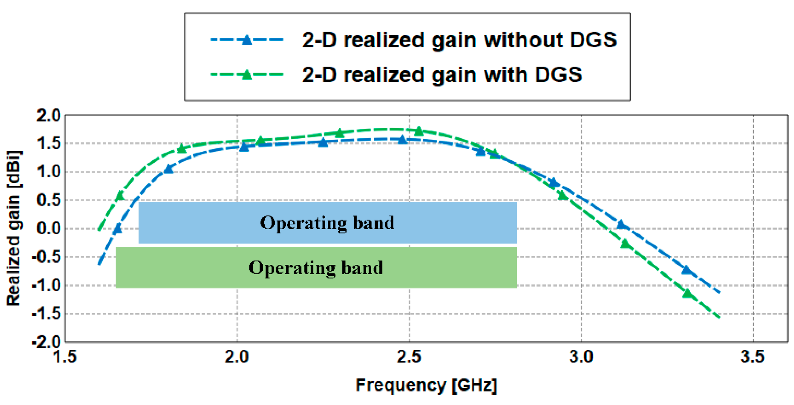
| 1 | 1.95 | 1.87 | −19.66 | −20.34 | 2.5 | 2.5 | 1.066 | 1.118 | 92 | 93 |
| 2.45 | 2.45 | −14.59 | −18.09 | 4.0 | 3.0 | 93 | 93 | |||
| 2 | N/A | |||||||||
| 3 | 1.94 | 1.86 | −20.26 | −22.8 | 2.5 | 3 | 1.068 | 1.166 | 92 | 92 |
| 2.4 | 2.5 | −15.03 | −18.74 | 4 | 3 | 93 | 92 | |||
| Distance (mm) | SAR Values (W/kg) | |||
|---|---|---|---|---|
| 1 g Cube | 10 g Cube | |||
| 1.87 GHz | 2.45 GHz | 1.87 GHz | 2.45 GHz | |
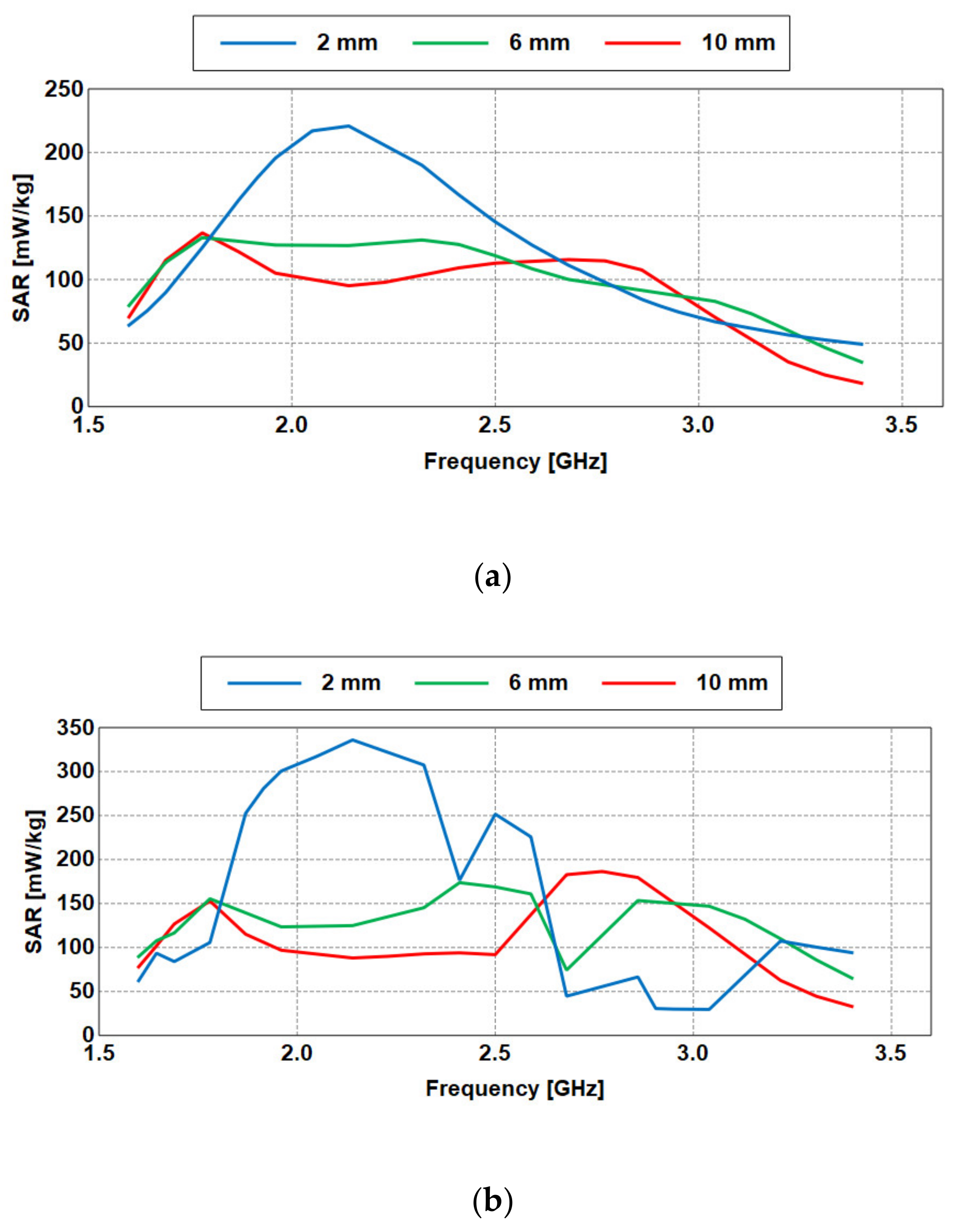
| 10 mm | 0.115 | 0.093 | 0.122 | 0.111 |
| 6 mm | 0.139 | 0.172 | 0.130 | 0.124 |
| 2 mm | 0.253 | 0.210 | 0.163 | 0.157 |
| Distance (mm) | Realized Gain (dBi) | |
|---|---|---|
| 1.87 GHz | 2.45 GHz | |
| Free space | 1.46 | 1.75 |
| 10 mm | −1.75 | −1.44 |
| 6 mm | −3.81 | −3.72 |
| 2 mm | −7.18 | −7.05 |
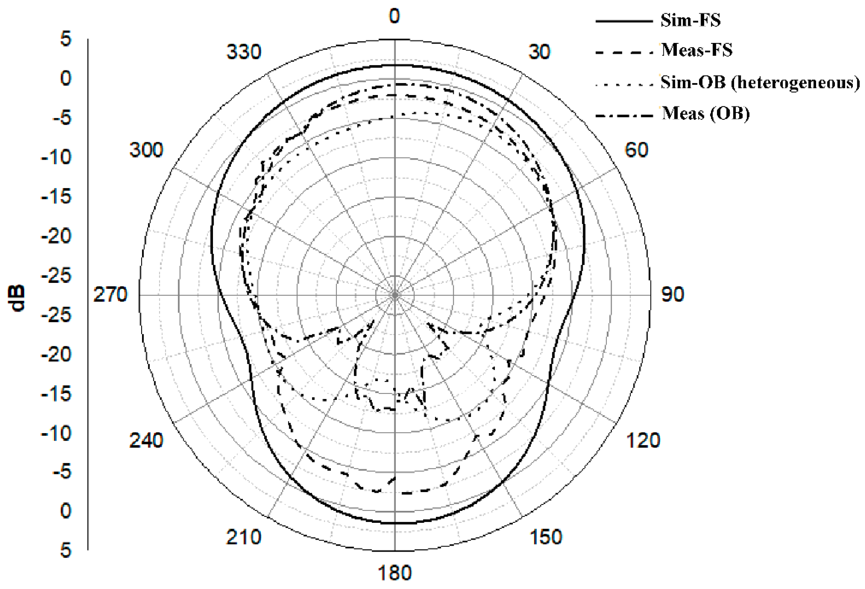
| Results | Resonant Frequency (GHz) | Reflection Coefficient (dB) | Bandwidth %/(MHz) | |
|---|---|---|---|---|
| Sim. | FS | 1.87/2.45 | −20.34/−18.09 | 49.04/1118 |
| OB | 1.9 | −21.71 | 49.74/1131 | |
| Meas. | FS | 1.8/2.38 | −10.33/−11.82 | 40.16/864 |
| OB | 2.44 | −13.09 | 11.44/281 | |
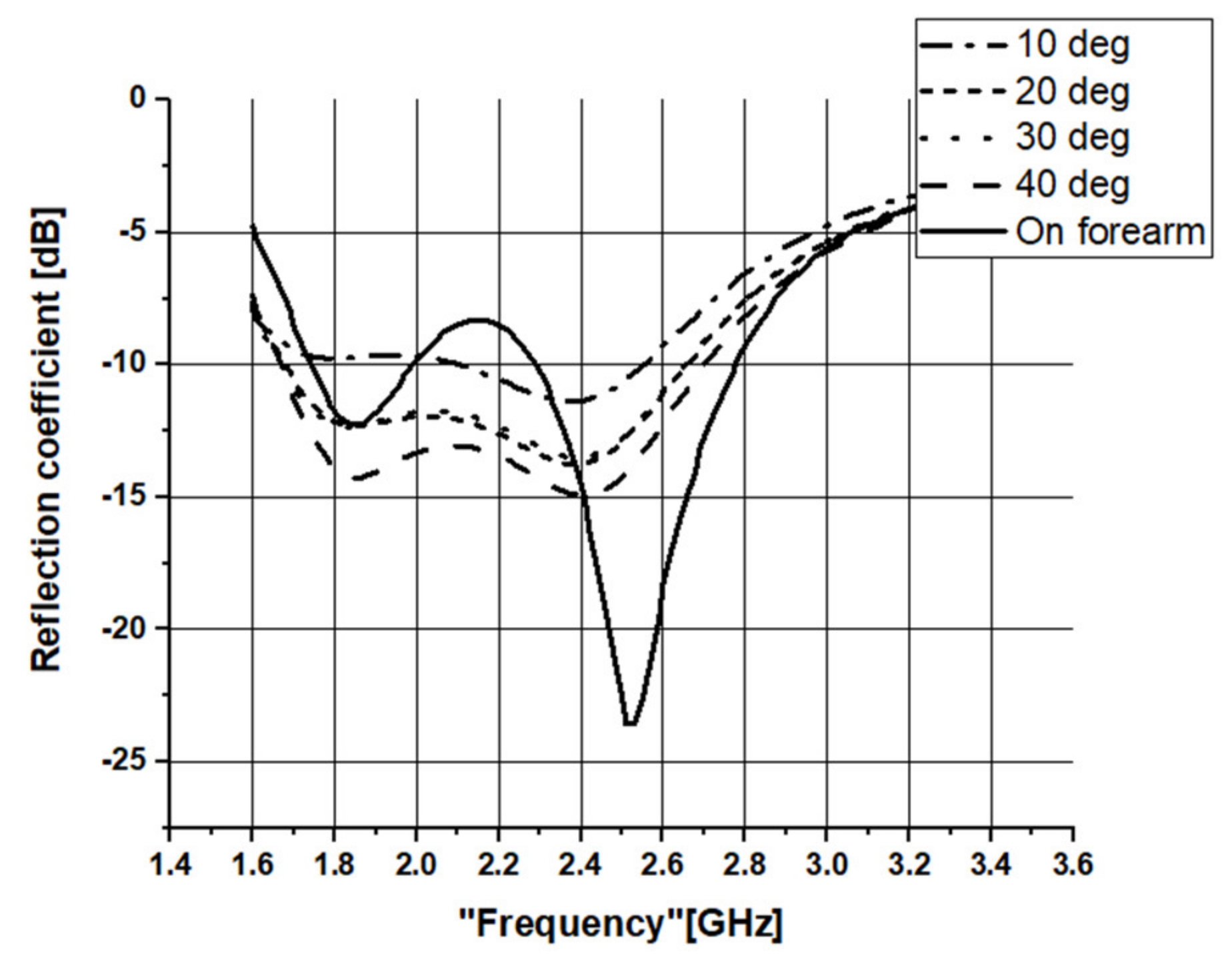
| Case | Operating Frequency (GHz) | Reflection Coefficient (dB) | Bandwidth (MHz) |
|---|---|---|---|
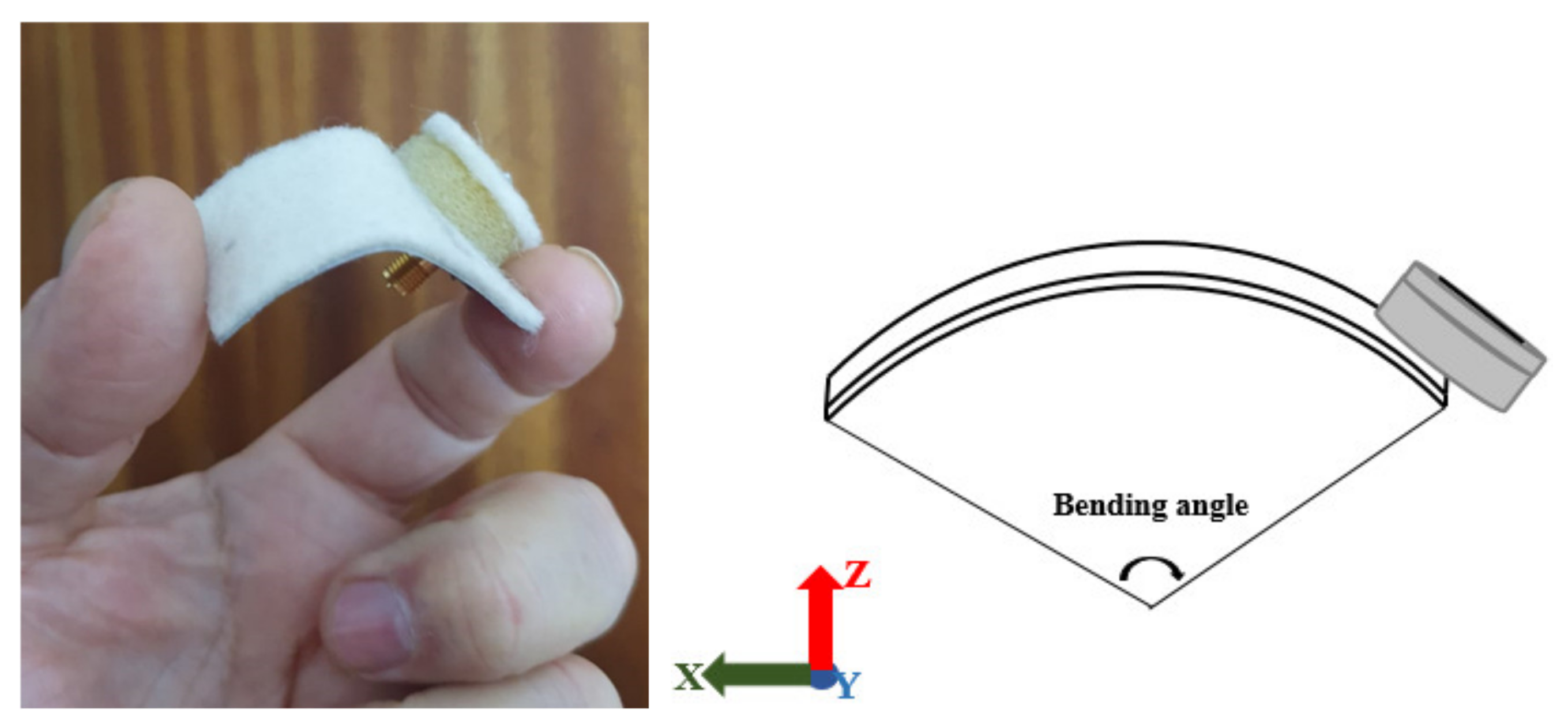
| Bent at 10° | 2.38 | −11.38 | 448 |
| Bent at 20° | 2.39 | −13.77 | 979 |
| Bent at 30° | 2.4 | −13.51 | 986 |
| Bent at 40° | 2.41 | −14.94 | 1032 |
| Bent on forearm | 1.85 | −12.27 | 249 |
| 2..52 | −23.68 | 487 |
| Ref | Antenna Dimensions (λg2/mm2) | Operating Frequency (GHz) | Bandwidth (%) | Gain (dBi) | Flexible? | Efficiency % |
|---|---|---|---|---|---|---|
| [31] | Radius = 0.26/ 25 | 2.45/5.8 | 10.9 (Meas) | −5.1 (2.45 GHz) 3.3 (5.8 GHz) (Mea) | Yes | 16 (2.45 GHz) 54 (5.8 GHz) (Sim) |
| [32] | 0.63 × 0.57/ 60 × 55 | 2.45 | 12.88 (Sim) | Not reported | Yes | 74–90 (Sim) Over the entire operating bandwidth region |
| [22] | 0.84 × 0.42/ 50 × 25 | 2.45 | ~34.39 (Sim) | 5.2 (Sim) | Yes | 72.1 (Sim) |
| [33] | 0.77 × 0.58/ 80 × 60 | 2.45 | 12.8 (Sim) | 6.07 (Sim) | Yes | 59 (Sim) |
| [34] | 0.57 × 0.49/ 53.6 × 45.8 (of the patch) | 2.45 | 6.1 (Meas) | 7.8 (Meas) | Yes | 90 (Meas) |
| [35] | 0.51 × 0.91/ 50 × 19 (PIFA antenna) | 2.45 (Sim) 2.63 (Meas) | 28 (Sim) 31 (Meas) | 1.78 (Sim) 1.2 (Meas) | Yes | N/A |
| This work | 0.35 × 0.17/ 50 × 25 | 1.87/2.45 (Sim) 1.8/2.38 (Meas) | 49.04 (Sim) 40.16 (Meas) | 2.5 (1.87 GHz) 3 (2.45 GHz) (Sim) | Yes | 93 (1.87 GHz) 93 (2.45 GHz) (Sim) |
Publisher’s Note: MDPI stays neutral with regard to jurisdictional claims in published maps and institutional affiliations. |
© 2021 by the authors. Licensee MDPI, Basel, Switzerland. This article is an open access article distributed under the terms and conditions of the Creative Commons Attribution (CC BY) license (https://creativecommons.org/licenses/by/4.0/).
Share and Cite
Elias, B.B.Q.; Soh, P.J.; Al-Hadi, A.A.; Akkaraekthalin, P.; Vandenbosch, G.A.E. Bandwidth Optimization of a Textile PIFA with DGS Using Characteristic Mode Analysis. Sensors 2021, 21, 2516. https://doi.org/10.3390/s21072516
Elias BBQ, Soh PJ, Al-Hadi AA, Akkaraekthalin P, Vandenbosch GAE. Bandwidth Optimization of a Textile PIFA with DGS Using Characteristic Mode Analysis. Sensors. 2021; 21(7):2516. https://doi.org/10.3390/s21072516
Chicago/Turabian StyleElias, Bashar Bahaa Qas, Ping Jack Soh, Azremi Abdullah Al-Hadi, Prayoot Akkaraekthalin, and Guy A. E. Vandenbosch. 2021. "Bandwidth Optimization of a Textile PIFA with DGS Using Characteristic Mode Analysis" Sensors 21, no. 7: 2516. https://doi.org/10.3390/s21072516