1. Introduction
Manufacturing automation makes use of essential geometric features in object reasoning for robot planning. Features are defined as a combination of a group of relative geometric entities like a face, edge, loop or a vertex [
1]. Examples of features include holes, grooves, slots, walls, etc. Ultimately, more complicated features are composed of such simpler features and are vital in robot path planning. Traditionally, localising such features is done via CAD. In applications like re-manufacturing of damaged parts, where no CAD model of the work-piece may be available, 3D computer vision becomes essential for distinguishing the defective regions [
2], localizing salient features [
3,
4], etc. before robotised manufacturing or re-manufacturing can take place. Poorer resolution in 3D scans produced by inexpensive 3D vision systems further highlights the challenge in making robotic automation commonplace in industrial applications. Moreover, localizing features becomes all the more important when robots need to physically interact with the work-piece, i.e., for tasks such as assembly where haptic feedback is important for control. In this work, we study the haptic geometric refinement of features like holes, edges, slots (as shown in
Figure 1) in models produced by inexpensive 3D scanners.
Current practice makes use of a large spectrum of 3D vision technologies to scan work-pieces to derive 3D kinematic models for robot motion planning. The availability of low-cost 3D vision systems encourages the use of robots in less-structured environments, e.g., workshops. For example, robotic manipulators nowadays are equipped with both position sensing and depth sensing along with torque sensing. Although the position sensing is within the
mm scale accuracy, the depth sensing is slightly rougher. However, the proposed framework allows the use of fine torque sensing also available on-board to improve the quality of depth sensing by refining missing features. One of the challenges, however, is represented by the typically poorer resolution of such low-cost 3D vision systems, compared with higher-end alternatives. Although high-quality portable scanners [
6] overcome these challenges using a variety of techniques [
7], solutions to improve inexpensive and portable scanning would open up opportunities for small and medium enterprises (SMEs) to make use of cost-effective robotic systems. An additional constraint apart from the high cost of high-quality scanners is that they require in-situ scanning, i.e., the work-piece often has to be taken into another facility for scanning [
8]. We propose to bridge these gaps by providing a flexible framework capable of refining select features interactively, to enable their localisation for robotic planning later.
The proposed framework has the following workflow where an operator (i) has access to both the actual work-piece and its 3D scan; (ii) evaluates which salient features are missing from the scan; (iii) uses a haptic stylus (i.e., a device capable of measuring 3D positions as well as 3D interaction forces at its end-tip, as detailed later) to physically interact with the actual work-piece, around such specific features; (iv) updates the geometry of the scan in real time using the position and force information from the haptic stylus.
This work, however, will only focus on the latter points, i.e., on the way the initial scan is updated, for the purpose of enhancing salient features based on data derived from the physical interaction with work-piece via the haptic stylus. More specifically, in this paper we will not address the subsequent robotic motion planning, including calibration problems between robot coordinates, work-piece coordinates and 3D scan coordinates. Furthermore, we shall assume that the operator, based on his/her experience, knows which salient features are needed for a specific task. In this sense, we will not deal with exploration strategies which vary from operator to operator and are task-dependent.
As explained in the following sections, we use a discrete mesh as a numerical estimation of the actual work-piece surface. Initialized with a 3D scan, this mesh is continuously updated based on the physical interaction between the work-piece and the haptic stylus held by an operator. The novelty of our work is that the geometric update of the mesh is based on the haptic mismatch between the actual force, as sensed by the haptic stylus from the interaction with the actual work-piece, and the expected force, which is predicted based on the geometry of the surface and current position of the stylus. It should also be noted that the information used to update the geometry of the surface in this process not only makes use of the 3D position of the stylus end-tip, as typically done in digitization techniques, but also of the 3D forces (magnitude and direction) arising from the actual interaction, hence the name ’haptic’ stylus. In particular, the mesh (from the 3D scan) is updated only in presence of haptic mismatch. The 3D position of the stylus determines where to update the mesh while the 3D forces are used to determine the direction and magnitude of the update. This is in contrast with the other approaches in haptic digitization. Specifically, most methods use the knowledge that there was physical contact at a location as a way to record this location as part of the surface model. This will be detailed in the next section. Some challenges with these methods include thresholding the sensed contact to avoid outlier points, filtering the recorded points and fitting a surface on them. The computational demand in implementing these methods in real time is yet another challenge. The proposed framework overcomes these challenges by using the forward prediction of haptic feedback obtained from the initial 3D scan and then uses the backward haptic feedback to refine it, in real time.
The rest of the paper is organized as follows. In
Section 2, we present various scanning and digitization methods as a background for this work and highlight our novelty. In
Section 3 we introduce the proposed framework and mathematically define haptic mismatch.
Section 4 simulates haptic mismatch through numerical simulations of the proposed framework on smooth differentiable surfaces to validate the geometric convergence of the different features being refined. Finally
Section 5 details the experimental refinement of missing features (like holes, edges, slots) from 3D scans of objects, followed by the conclusions and future scope of this work.
2. Background
In this section we review different non-contact and contact based scanning technologies and the trade-offs between them. The challenges in using high end scanners in terms of cost, additional expert skill requirement, lack of mobility and limited scanning space are identified as gaps our framework aims to address. Various available 3D model formats for representing the surfaces are presented. Haptic based scanning methods are surveyed to discuss the framework’s relevance in robotics research. Finally, haptic sculpting literature and its relevance to our work is studied to highlight the novelty in our approach.
2.1. Non-Contact and Contact Based Scanning Technologies
Manufacturing industries have employed non-contact based 3D scanning technologies such as laser triangulation, structured light, time-of-flight and photogrammetry [
9] in part inspection and reverse engineering applications [
10]. Laser triangulation offers high resolution and accuracy but suffers from sensitivity to surface properties [
11] (like roughness, reflectivity, transparency, etc). Similarly, structured light scanners are dependent on appropriate lighting conditions [
12], time of flight sensors cannot detect concavities in shape and photogrammetry requires high computational power [
13]. Optical 3D coordinate measure machines of the manufacturer ATOS GOM [
8] and its competitors use a wide variety of scanning technologies including structured light scanning with high accuracy results and often are able to capture fine features too, but prove very expensive for setting up and require expert skill to operate.
Different non-contact sensors capture 3D information and use a variety of output formats. Popular models to visualize the 3D geometry include point clouds, polygonal meshes, Non-uniform rational basis spline (NURBS) surface models, etc. Interconversion between these models is well established. In this work we use Occipital’s structure sensor [
14] which comprises of an IR structured light projector and a camera that captures the reflected pattern. A set of algorithms compute the 3D scene information over several iterations by tracking the relative position from which a frame of 3D information was recorded over time. A triangular mesh is produced, like the one rendered in
Figure 1. Triangular meshes are widely used in 3D vision and a recent approach to building a mesh from a single image was presented in [
15] where the depth map of an image was used to
wrap a plain mesh for synthesising novel views. The proposed work is an analogue to this method but is driven by forces from physical interaction instead of visual features. Specifically, the
wrapping of a mesh to conform to absent geometric features using haptic feedback is the haptic analogue we present.
Among contact based high resolution scanning methods, one of the early inventions is the Atomic Force Microscopy (AFM) method [
16]. This method is worth mentioning since our work is fundamentally similar to this. Although it allows for measurements at the
μm – mm level and understanding material properties like magnetism, elasticity, etc., one of the main drawbacks is the limited mobility and the special requirements like vacuum environments for operation. Coordinate measuring machines (CMMs) have also used physical contact to improve coordinate metrology [
17]. Other contact based scanning methods like Tactile probing [
18] for manufacturing applications like part inspection [
19] and reverse engineering [
20] by linking vision to touch are also not new. However, Refs. [
17,
18,
19,
20] specifically require CAD and are primarily post-processing methods limited to verifying part geometry after manufacturing. Our framework on the other hand, is a pre-manufacturing process for refining 3D scans with finer features omitted during scanning.
2.2. Haptic Digitization
Digitization is the process of reverse engineering virtual models of actual objects. Conventional contact based scanning methods for digitization largely targeted at part inspection were discussed in the previous subsection. However,
haptic digitization, i.e., the use of active touch to reconstruct the shape of an object for perception of size and position is also an active field of research. Haptic perception caused when people move their hands over an object to decipher smoothness, roughness, curvature, etc. [
21] is attributed to
Haptic exploration. Haptic exploration may be used for feature detection, i.e., of bumps, cracks, ridges, etc. Early approaches to this problem proposed incremental updates of a probabilistic map of the environment for a known smooth surface [
22] and unknown objects [
23]. This is also known as
Haptic SLAM. Similar implementations using particle filters [
24] have demonstrated accurate reconstruction of a Rubik’s cube and [
25] presented visual-tactile fusion for object recognition with fingered hands. Object classification through blind tactile exploration in the presence of sensory noise was also shown in [
26]. Some more noteworthy robotics applications of haptic digitization are surface patch reconstruction [
27], localization of objects [
28], improved grasp planning [
29]. Interesting approaches to digitization by means of fusing visual information with touch information have also been done for grasp planning applications as listed next. Ilonen et al. [
30] used visual information and tactile information together to help extract shape information and reduce uncertainty, however with the assumption of symmetric objects. An implicit surface was modelled as a Gaussian process in [
31,
32,
33,
34] and further refined using touch information. Shape priors were extracted from visual images and then corrected using tactile data for 3D shape perception [
35].
We next study various techniques in sculpting, which is the step that follows digitization of an object.
2.3. Haptic Sculpting
Our work draws inspiration from many sculpting techniques already in use for computer aided manufacturing applications. Haptic sculpting constitutes subtracting of materials from digital objects [
36] to modify their shape. Haptic sculpting has been used for product prototyping [
37], redesigning a reverse engineered product [
38], repairing incomplete measured data [
39] and collaborative sculpting [
40]. To aid with parametric representations in CAD like NURBS and Basis spline (B-Spline), specialized haptic sculpting methods were also devised to perform sculpting of rigid [
41] and deformable objects [
42] and finally manufacturing planning [
43]. Out of all these approaches, the work presented in [
44] is the closest to our work. Interestingly they use haptic sculpting for the more fundamental process of digitization by initializing the digital object with a virtual clay. This virtual clay is sculpted through volume subtraction virtually using just position data from the haptic interface. Our work uses
actual haptic feedback, i.e., the force readings recorded during physical interaction with the object and differs from them fundamentally in this sense.
2.4. Theoretical Comparison and Challenges across Touch Based Scanning Methods
Most of these surveyed approaches focus on extracting the shape of an object or a surface using vision or touch or both. The common applications across them were either (i) object shape estimation/reconstruction/repair or (ii) localization of object by way of reconstruction or acquiring samples of surface points. One commonality among these methods is the use of a sensorized stylus or a tactile array capable of providing end-tip position and contact (on/off) information to perform point-wise virtual mapping using touch information—a binary view of physical touch. Spatial location
is usually associated with a
target value which is indicative of whether the point is in the interior (
), on (
) or in the exterior (
) of the surface in question. A commonly used model in these approaches [
31,
32,
33,
34,
45] is a gaussian process implicit surface (GPIS). It would seem an appropriate choice of a surface model since it readily incorporates the uncertainty involved in measurements. There are other models also used like the point cloud in [
29,
30], occupancy grids/voxels [
24,
44] and surface polynomials in [
27,
46,
47]. However, the touch information collected in all these approaches is binary—evaluating whether or not contact has occurred without using the forces sensed at the point of contact and the vital information of surface normal that it encodes. This is one major gap we address in our proposed framework—we use both the magnitude and directional information provided by the forces at the point of contact to extract/refine the perceived shape of the surface. A few works [
28,
48] do use the forces sensed at the contact point for localisation purposes, but not for refining the perceived shape of an object. Moreover, their method relies on prior knowledge of the object geometry before localisation is possible and cannot be used with unknown objects as is required in remanufacturing applications.
From a computational standpoint, most of the approaches collect touch information as a tuple
, where the
is obtained by evaluating whether or not contact occurred and the GPIS or any model they use is retrained/regressed to capture the newly perceived geometry. For fully automated scenarios while these approaches may be useful, in cases that require interactive and intuitive interfacing with a human operator in the loop (for instance in manufacturing and remanufacturing settings) such retraining of models present a computational challenge. Moreover, most of these methods use tactile arrays for collecting touch information, which are not ideal for abrasive or rough surfaces typically encountered in remanufacturing settings. In this work we bridge these aforementioned gaps by proposing a novel framework that allows for interactive haptic sculpting of a scanned surface by using both the magnitude and directional information from the sensed physical contact. The model used is a 3D polygonal mesh, which is refined/morphed explicitly (as opposed to an implicit parameter that encodes the surface information) using differential equations. This is in contrast to the retraining step that is the state of the art currently [
45]. By designing the differential equations with a visco-elastic form, we ensure the refinement is intuitive and the mesh deforms in a
clay-like manner to
actual forces exerted by the human operator on the real object using the haptic stylus.
These works in touch based scanning, haptic digitization, Haptic SLAM and haptic sculpting are very similar to the proposed framework in this paper. However, our work differs from them in some fundamental ways. Our key contribution is the idea to use the geometry available from the 3D scan to compute an expected haptic feedback at a point and compare it with actual haptic feedback to derive a haptic mismatch. This in turn is used to drive the update of the 3D scan. In terms of how the virtual model is morphed, most of the surveyed methods assume voxel-based representations of objects or GPIS and involve volume subtraction or updating voxel occupancies and gaussian process regression for mapping the surface of an object. Our methodology morphs the 3D model locally at the surface directly.
In the following section, we provide an overview of the proposed framework following which we mathematically formulate it. We also formalise the notion of haptic mismatch and define the two ways in which the update of the 3D scan at a local point occurs, i.e., position and orientation corrections.
3. Proposed Framework
We propose a framework whereby a human operator, after a visual inspection of the initial scan, may proceed to a manual refinement of the scan by means of a haptic stylus used to physically interact with the actual, rigid surface (
Figure 2b). Consider a rigid object and a scan of its surface as sketched in
Figure 2a. The scanned surface very often will fail at capturing certain details, e.g., holes, sharp edges etc. The force arising from the physical interaction with the actual surface will be used as input signal to a filter, which will adapt the triangular mesh derived from the the scan locally, i.e., in the area of physical interaction and with a magnitude proportional to the force itself.
To record the haptic feedback, we use a haptic stylus as shown in
Figure 2b. The haptic stylus will be equipped with a force sensor that provides the haptic feedback of the
actual interaction with a surface. Additionally, the position and orientation of the stylus are also to be sampled for real-time rendering purposes.
Upon surface-tool interaction by the haptic stylus with a real surface an actual haptic feedback is recorded in terms of forces and torques. Concurrently, the internal model predicts the expected haptic feedback. The internal model is a haptic rendering of the mesh structure obtained from the 3D scan, i.e., the geometry of the 3D scan is used to compute a prediction of the force feedback to be expected when a tool comes in contact with a surface point. This prediction is then compared with the actual haptic feedback to produce a haptic mismatch. The haptic mismatch coupled with the haptic update rules of the framework correct the surface scan geometry in terms of position and orientation of individual surface points to reflect the real surface’s geometry accurately.
To model surfaces in 3D we use triangular meshes because they allow to work with a locality in the model while keeping the rest of the regions of the mesh intact. This allows for efficient implementations. To mathematically describe the mesh obtained from the scan of the real surface in a reference coordinate system, we define state variables. These variables will be used to define the interaction function used to calculate the expected haptic feedback, given a position of the haptic stylus. The two types of haptic mismatch for position and orientation correction of a surface point in the scan are presented with qualitative case studies. Briefly, these cases are meant to understand the positional and orientation haptic mismatch for different errors in the surface scan w.r.t the actual surface. For instance, based on whether or not the haptic stylus is penetrating the 3D mesh, an expected haptic feedback—both in terms of magnitude and direction may be computed. This may or may not be non-zero and both these cases may correspond with a zero or non-zero actual haptic feedback sensed. Studying these cases will help understand the working of the proposed framework. Consequently, the mathematical rules to correct the haptic mismatch are summarized and a numerical validation of these rules for one surface point is presented. These rules constitute the aforementioned haptic update. Finally, error metrics are defined and a numerical simulation of the haptic update is carried out in the 3D case to quantitatively characterize the framework’s performance.
3.1. State Variables
Figure 3a describes the virtual surface scan as a piece-wise linear approximation of the actual surface geometry. Since the scan of any surface is a discretised
estimate of the surface geometry, we denote the state variables related to the scan with the superscript
and those related to the actual surface without. The state variables are defined in the space frame
. Considering the haptic stylus’s pen-tip at position
, the closest point to the pen-tip on the mesh is denoted by
, the barycenter/centroid of the closest face. Similarly, the orientation information of the geometry is captured by the surface normal variable
. These state variables will be adapted based on sensory inputs as explained in the next subsection.
The basic idea of the framework is to adapt (, ) based on haptic mismatch. Only when the haptic stylus is in contact with the surface, i.e., non-negligible interaction forces are recorded. The framework aims to adapt and such that the respective face is on the tangent plane to the surface at the point of interaction.
3.2. Calculating Expected Haptic Feedback
The mesh represents the actual surface to the best of the sensor’s accuracy and as such, it will be used to predict interaction. In other words, if the haptic stylus was to penetrate a given face of the mesh, we would expect an interaction force perpendicular to the face normal (assuming no friction with the actual surface). In order to calculate the
expected force (haptic feedback), it is useful to define a signed distance
h as:
where · is the Euclidean dot product. This is shown in
Figure 4a. Given the haptic stylus position
, we define the
expected haptic feedback
using the haptic rendering function
and the normal at the point in the scan as:
The nature of
is depicted in
Figure 4b and in this work, is defined as an adjustable sigmoid function:
where
is the depth tolerance—the minimum distance from the surface at which, interaction forces are said to exist between the point of interaction and the surface and
—the maximum force the model simulates.
controls the point of inflection of the sigmoid function and may be chosen such that the interaction force is strictly zero for positive
h, i.e., when there is no penetration. The interaction force function
is meant to be a smooth transition between a zero and non-zero contact over a range of penetration depths.
The framework’s performance is sensitive to the interaction force function along the domain—signed distance h. The lower the depth tolerance, the stiffer the function, i.e., for lower displacements, a higher contact force is estimated. Furthermore, the interaction force function allows a choice over the range of forces (from 0 to ) to be expected in an application and a smooth variation over that range.
3.3. Haptic Mismatch Correction
We define
haptic mismatch as the difference between the actual interaction and the virtual interaction calculated w.r.t the mesh. The most common case while evaluating a
haptic mismatch is when the haptic stylus is hovering in space and is neither in contact with the mesh, nor the actual object. We label this as Case 1 as shown in
Figure 5 where the actual haptic feedback
and the expected haptic feedback
are both absent, i.e., null in magnitude. When the haptic stylus is only in contact with the mesh and not the surface, a non-zero
expected haptic feedback
is calculated. On the other hand, when in contact with only the surface and not the mesh, a non-zero
actual haptic feedback
is recorded. Cases 2 and 3 describe these. Finally when the haptic stylus is in contact with both the mesh as well as the actual surface, the framework evaluates non-zero
and
as seen in Case 4. Note that the
actual haptic feedback will be sensed in the haptic stylus frame
and must be converted and expressed in space frame
when computing haptic mismatch. To match the scan geometrically with the actual surface, we design the framework to align all the face normals of the scan to the actual surface normals at their respective positions. The haptic mismatch is said to be corrected fully if the
expected haptic feedback at every discrete point on the scan matches the
actual haptic feedback at that same location on the actual surface.
Mathematically, a face in a mesh is fully described by its barycenter (position information) and its face normal (orientation information). These are the two vector variables that will be adapted to correct the haptic mismatch using the expected and actual haptic feedback. The update of the barycenter is defined as the position correction and the update of the face normal as the orientation correction.
3.3.1. Linear Haptic Mismatch:Position Correction
The purpose of the position correction of the face barycenter on the mesh is to ensure that it lies on the plane described by the actual point of contact and the surface normal there. To this end we define the linear error in forces by:
The correction of linear haptic mismatch is essentially a linear translation of the face of interest on the scan along its normal direction . The idea is to preserve the normal information suggested by the scan until new information from the actual surface is perceived through the actual haptic feedback . Once there is an actual interaction force encountered by the F/T sensor, would increase to a non-zero value, thus moving the face of interest along its normal until . This would only happen when the barycentre of the scan face is on the actual surface.
In the case studies in
Figure 5, the point of contact may be deciphered from the haptic stylus position while the surface normal may be obtained from the forces sensed. Since
in Case 1 always, there will be no position correction when the haptic stylus is not in contact with both the mesh and the surface. In Cases 2 and 3, the correction of haptic mismatch would entail purely position correction.
3.3.2. Rotational Haptic Mismatch:Orientation Correction
Once the barycenter of the face (from the mesh) lies on the actual surface, the next step is to ensure the face normal matches with the surface normal. We define a rotational error in forces by:
The cross product rule may be viewed as analogous to inducing a moment on the face to rotate it until rotational equilibrium is reached. This would occur when both the expected haptic feedback and the actual haptic feedback match in terms of their vector direction. In other words, the unit vector along describes the actual surface normal at the point of contact. The orientation correction is performed by rotating to align with the unit vector along once the linear haptic mismatch is corrected through the position correction. Note that the interaction force at any point on the surface is along the surface normal there. Hence, the cross product of and would be a zero vector if the two faces were aligned. This cross product thus defines the direction about which the needs to rotate to align with the surface normal, described by the unit vector along . Finally, a triple cross product with serves the purpose of deriving the rotational haptic update.
The overall correction of
haptic mismatch may be summarised as simply a positional correction for Cases 2 and 3 and a positional and orientation correction for Case 4. This may also be noticed from
Figure 5 which shows that
may be non-zero only in the last case.
3.4. Haptic Update
A summary of the
haptic update rules qualitatively described in the previous subsections is presented next. The state variables are (i) the barycentre
i.e., centroid of the closest face on the scan to the haptic stylus and (ii) the face normal
. The haptic mismatch is carried out in two parts as described before:linear and rotational. The overall correction of
haptic mismatch is done by solving the following differential equations defined on the state variables:
Together, Equations (
6) and (
7) constitute the
face dynamics of the scan. The variables in these update rules are listed out in
Table 1. Typically, the scan of a surface is a close enough approximation of the actual surface and the refinement of the scan should be such that it does not morph too much too abruptly. To ensure this behaviour, we introduce admittance coefficients
and
which control the spatial evolution of the face barycentre
and normal
. These also contribute to ensuring stability of the
haptic update.
5. Experimental Refinement of Geometric Features
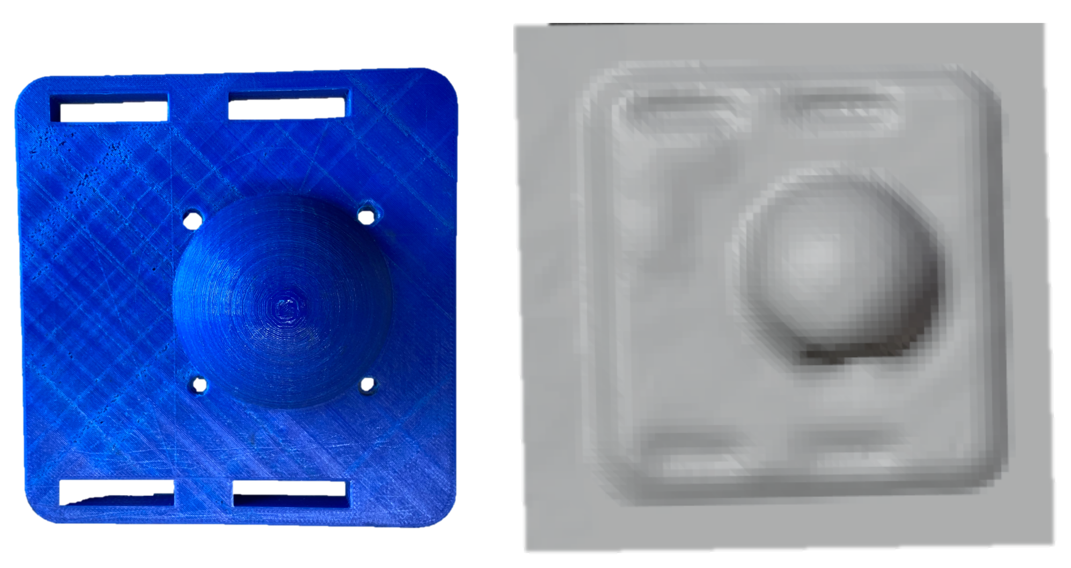
In the previous section, the numerical convergence of the proposed framework was performed on smooth differentiable surfaces. To validate the framework’s efficacy on real geometric features suitable for robotic assembly, we pick objects with distinct features like holes, edges and slots (see
Figure 12). It may be noted that the CAD (
Figure 12b) is not usually available in remanufacturing settings, but is shown here for the purpose of highlighting the features absent in the 3D scan of the same object (
Figure 12c. Although the missing features in these objects are primitive ones (holes, edges and slots), a vast majority of the geometric features in industrial applications are composed of these. To refine these missing features in the 3D scans, both position and force data from the haptic stylus were obtained as described next.
5.1. Data Acquisition Methods
The proposed framework refines the
mesh* using the haptic stylus position (
) and force data (
). Note that all these quantities must be expressed in the space frame
, i.e., the necessary transformations for the mesh variables (
) and the haptic stylus variables (
), must be computed between the different reference frames shown in
Figure 13. The transformation from haptic stylus frame to space frame is:
where,
is the rotation matrix that describes the 3D orientation of the haptic stylus and
is the 3D position of the haptic stylus w.r.t space frame
A similar transformation
was calculated for the mesh variables by using the texture map obtained from the 3D scan. The space frame was visually located in the image space and the transformation matrix was constructed by using calibration points manually selected in
Blender, an open source rendering engine used for the purposes of visualisation in this work.
The geometric refinement is performed in the neighborhood of the closest face
with barycenter
to
in
mesh*. In this work, the closest point after a manual initialisation, was iteratively searched for in real-time within all the faces
f in the 1-neighborhood
ROI as discussed in Equation (
12) in
Section 4.3.
The normal
for this
f* is obtained from the mesh structure. Since the loadcell frame {
l} is aligned with the stylus frame {
h}, the
actual haptic feedback
sensed in {
l}
was converted into space frame coordinates by a simple rotation transformation as:
The
hatptic update of
f* is then performed as per the Equations (
6) and (
7) in
Section 3.4 and a Laplacian deformation of the 1-neighborhood
ROI was used to refine the immediate locality as discussed in
Section 4.3. We next present the experimental details and the geometric refinement of features via haptic exploration of features and the consequent results.
5.2. Experimental Protocol
The procedure followed to perform the geometric refinement of features is explained in
Figure 14a. The human in the loop allows for
visual inspection of the features deemed important to the process and enables interactive usage of the proposed framework. The 3D scan is updated based on the perceived haptic mismatch until it is minimised. The 3D scans of the two objects with more than 4 holes missing, and smoothed out edges and slots were refined using the proposed framework. All the missing features were successfully refined and feature detection was performed in post-processing.
The experiment was conducted using three Desktop machines (see
Figure 14b): Quanser PC, Motion Capture PC and the Rendering PC. The Quanser PC was connected to a
Quanser QPIDe Terminal Board and analog data from the
ATI Mini40 6-axis F/T sensor (mounted between the handle and the pen-tip—see
Figure 13) was sampled at 200 Hz. The
ATI Mini40 6-axis F/T loadcell outputs the sensed forces in terms of analog voltages for:
fx,
fy and
fz. These readings were calibrated to reflect the sensed forces (in
N) in the loadcell frame of reference {
l} (which is aligned with {
h} at all times). Note that for calculating the haptic mismatch, these forces must be converted and expressed in space frame
. We next discuss the process of obtaining the pose of the haptic stylus, which allows for this
conversion of the sensed forces.
The Motion Capture PC communicated with the PTI Phoenix Visualeyez II VZ4000V Motion Capture system to track the 3D position of Motion Capture LEDs (markers) mounted on the hand-held haptic stylus. The haptic stylus pose was calculated from this and a UDP socket was written to communicate this information () to the Quanser PC.
The pose of the haptic stylus was computed by implementing an iterative filter that considers the pose of a rigid body in space and describes it as a spring-damper problem in linear and rotational terms. Briefly, this filter makes use of the redundancy in the number of markers mounted on the object to provide a real-time pose of the haptic stylus, despite occluded markers. Ultimately, for the working of the proposed framework, the pose of the haptic stylus is needed. For more details, the reader is referred to [
51] The rotation
obtained from the pose is used to compute the forces sensed by the loadcell in space frame, which is the actual force feedback
to be used for refining the geometric features in the proposed framework.
All of this information was combined on the Quanser PC to compute the
haptic update and morph
mesh* to conform to the actual surface geometry. To decrease the burden of computation, the rendering was done on another PC, labelled as the Rendering PC in
Figure 14b. The vertex set of the morphed neighbourhoods were communicated through UDP to the Rendering PC to help visualize the result of the
haptic update. A snapshot from the video of real-time haptic manipulation is shown in
Figure 15.
The haptic stylus was used by a human operator to perform haptic exploration to refine the missing features in a 3D scan of an object. Since
is an actual force feedback during the experiments, only the
expected interaction force
was calculated using haptic stylus position
and the refinement of
mesh* was done. The interactive nature of the proposed framework may be observed in the compiled videos of haptic exploration [
52].
5.3. Geometric Refinement via Haptic Exploration
We now discuss the results of selective feature refinement in two different objects. Specifically we work with holes, edges and slots as seen in
Figure 16 and
Figure 17. The viscous coefficients of haptic update, i.e.,
= 0.1 mN
s
,
= 0.1 N
s
for state dynamics’ evolution were heuristically set so that
mesh* responded intuitively to the contact force imposed by the human operator. The rule of thumb to set these parameters is to observe the update rate of the mesh which depends on the sampling rate of position and haptic feedback and the stability of the mesh update. It is advisable to initiate at a very low value—which makes the update very sluggish and then increase until it is responsive enough to human movements. Upon performing haptic exploration on features marked in red in
Figure 16, the refined
mesh* clearly showed features absent in the initial
mesh*. It may be noted that the framework allows for selective refinement as seen in the different results, as opposed to an end-to-end highly accurate solution that expensive 3D scanners offer. This allows for the framework to be used flexibly and is also useful in defining the scope for feature recognition later. In
Figure 16c, only the holes of the object were refined, in (d) the edges were isolated and (d) shows the holes and slots highlighted better. We next present a methodology to benchmark our experimental results numerically.
The objective of the proposed framework is to enable localisation despite the poor quality of the 3D scans obtained from inexpensive scanners. To numerically validate the effectiveness of the proposed framework, we attempted to localise and match the
refined geometric features using iterative closest point algorithm. Specifically, the
refined-mesh* of the object in
Figure 17a and its CAD (
Figure 18a) were compared using this method. The procedure used was as follows: (i) Obtaining of
initial- mesh* (
Figure 17b) of object (
Figure 17a), (ii) Performing haptic exploration over
all features of interest (
Figure 17d), (iii) Gaussian curvature evaluation on the meshes for this
refined- mesh* and CAD, (iv) Clustering over the meshes to obtain
control points, (v) Point set registration on the
control points to align the
refined-mesh* and CAD-mesh (
Figure 18a) and (vi) After converting the meshes to point clouds, a cloud to cloud comparison to evaluate the error before and after haptic exploration. Note that haptic exploration was all the features to be highlighted in the object, i.e., holes and edges. The Gaussian Curvature [
53] with a heuristic threshold of 0.3 was evaluated over the segmented region of interest in CAD (
Figure 18a) and the
refined-mesh*.
Following the evaluation of gaussian curvature on both CAD mesh and refined mesh, we now have a set of vertices per mesh which marked a high curvature. k-means clustering was performed on these vertex sets to derive centroids of the features with
(may be automated depending on application). These clusters may be seen in
Figure 18b,c. These cluster centroids are vital to perform mesh alignment before comparing the two meshes for geometric differences. Note that without
haptic update performed over the
initial-mesh*, obtaining these features or localizing these clusters would not have been possible.
Point set registration was performed to align the two meshes (i)
initial-mesh* and (ii)
refined-mesh* with CAD as shown in
Figure 19. The control points derived from the gaussian curvature evaluation play a key role in performing this alignment of meshes—both for
initial-mesh* and
refined-mesh*.
Post alignment, the final step of evaluating the performance of our framework is to check if the geometric differences between the CAD and the refined scan were indeed less than those with unrefined scan. It may be observed in
Figure 20 that the cloud to cloud (C2C) absolute distances at the holes (which were the features that we performed haptic exploration over) are indeed lower for the
refined-mesh*.
Although the error does not vanish owing to human error, calibration error, etc. in the experiments shown above, the ability to perform haptic exploration of the workspace and update the robot’s knowledge is of critical importance in applications where the robot needs to physically interact with features like holes, edges, corners that may be absent in the 3D scan of the environment.


