Abstract
Electropolymerized redox polymers offer broad opportunities in detection of biospecific interactions of DNA. In this work, Azure A was electrochemically polymerized by multiple cycling of the potential in phosphate buffer saturated with chloroform and applied for discrimination of the DNA damage. The influence of organic solvent on electrochemical properties of the coating was quantified and conditions for implementation of DNA in the growing polymer film were assessed using cyclic voltammetry, quartz crystal microbalance, and electrochemical impedance spectroscopy. As shown, both chloroform and DNA affected the morphology of the polymer surface and electropolymerization efficiency. The electrochemical DNA sensor developed made it possible to distinguish native and thermally and chemically damaged DNA by changes in the charge transfer resistance and capacitance.
1. Introduction
There is an urgent need in the development of simple and reliable analytical devices for the detection of antioxidants, drugs, biomarkers, and toxic species required in medical diagnostics and food safety assessment [1,2,3,4,5]. Although conventional instrumentation, e.g., high performance liquid chromatography and capillary electrophoresis, offer quite sensitive and selective analysis of most analytes mentioned, they are rather expensive, time- and labor-consuming, and cannot provide necessary information in point-of-care (POC) format [6,7]. Immunoassay techniques frequently used in hospitals have some limitations related to the insufficient stability of antibodies and enzymes used as labels in the ELISA protocols and to interfering matrix effects, especially in testing biological liquids [8]. From other sensors utilized in determination of biologically active low molecular compounds, DNA-based assay is considered as one of most promising due to high variety of the species detected, higher stability of DNA oligonucleotides and aptamers against proteins, and simpler detection mode [9,10]. In particular, DNA-based sensors have been described for sensitive determination of antitumor drugs [11,12,13,14], reactive oxygen species [15], and antioxidants [16,17,18]. Aptamer-based biosensors detect with very high sensitivity mycotoxins, drugs, and cancer biomarkers [19,20,21,22,23,24,25]. Meanwhile, the detection of the DNA (aptamer)-analyte interactions and its conversion into an analytical signal remain a weak point of such biosensors. Traditional approaches require introduction of specific labels and are time consuming, although the sensitivity of the analyte determination is quite acceptable. Label-free biosensors utilize changes in permeability of the sensing layers caused by analyte implementation and measured mostly by electrochemical impedance spectroscopy (EIS) [26,27]. However, unspecific adsorption of the sample components affects the response of such biosensors, especially those based on Au able to form bonds with biogenic thiols. Necessity in additional treatment of the surface to block naked parts of the transducer not only complicates the biosensor assembling, but also decreases absolute values of the signal recorded.
Redox active polymers are frequently used in the development of label-free DNA sensors [28,29]. Polymers, mostly obtained by electropolymerization, show high efficiency of the DNA immobilization via electrostatic interactions and suppress undesired interactions with interferences. Then, noncovalent interactions between the underlying redox active support and biopolymer result in the changes of both electrostatic interactions and permeability of the surface layer. Interaction with analyte molecules affects both parameters due to partial shielding of the charges and/or charge separation in the recognition event. For this reason, monitoring of the redox activity of the polymers shows high sensitivity toward specific DNA interactions. Thus, DNA sensors based on polyaniline [30,31,32,33,34], polypyrrole [35,36,37], polythionine [38], and poly(neutral red) [15,39] have been described and successfully used for the determination of intercalation, DNA damage, and detection of hybridization with complementary DNA sequences. It should be noted that application of such modifiers frequently limits the measurement conditions by pH region required for redox signal recording (polyaniline) or by interference with reactive species able to react with electrodes near the redox activity of appropriate polymers (polyphenothiazines). Rather low selectivity of DNA intercalation monitoring was also reported [12,40].
Recently, we showed that polymerization of Azure B and proflavine followed by adsorption of double-stranded DNA results in sensitive determination of anthracycline drugs [40,41]. However, low solubility and aggregation of the dyes in solution and on the electrode surface can affect their polymerization and sensitivity of their interaction with DNA molecules. Meanwhile, electropolymerization from organic solvents seems less appropriate for the DNA biosensors due to hydrophobicity of the polymer interphase and difficulties in its compatibility with highly polar DNA molecules. Films polymerized from organic solvents are normally denser than those deposited from aqueous solutions and contain less water and small ions. This complicates charge transfer and redox signal generation on the polymer–DNA interface. In this work, we propose to perform electropolymerization in the presence of chloroform to improve the performance of the DNA sensor and increase sensitivity of the signal toward anthracycline drugs. Low amounts of organic solvent improve electropolymerization conditions due to higher solubility of the monomer while not affecting implementation of DNA molecules in the growing polymer film.
2. Materials and Methods
2.1. Reagents
Azure A (dye content 80%), DNA from fish sperm, and chloroform were purchased from Sigma (https://www.sigmaaldrich.com/ accessed on 11 January 2021). All the working solutions were prepared using Millipore Q® water. Electrochemical measurements were performed in 0.1 M phosphate buffer containing 0.1 M NaNO3 (pH 7.0). In the pH dependence experiments, appropriate pH value was adjusted in the range from pH = 2.0 to 8.0 by adding 0.1 M HCl or NaOH. Saturation of the working buffer with chloroform was performed by mixing in 4:1 volume ratio and stirring for 30 min. After phase separation, the aqueous part was taken for the electropolymerization experiments.
2.2. Apparatus
Voltammetric measurements were performed at ambient temperature using a portable bipotentiostat-galvanostat μStat 400 Metrohm DropSens (DropSens, S.L., Asturias Llanera, Spain). EIS measurements were performed with the FRA 2 module of the potentiostat-galvanostat AUTOLAB PGSTAT 302N (Metrohm Autolab b.v., Utrecht, Netherlands).
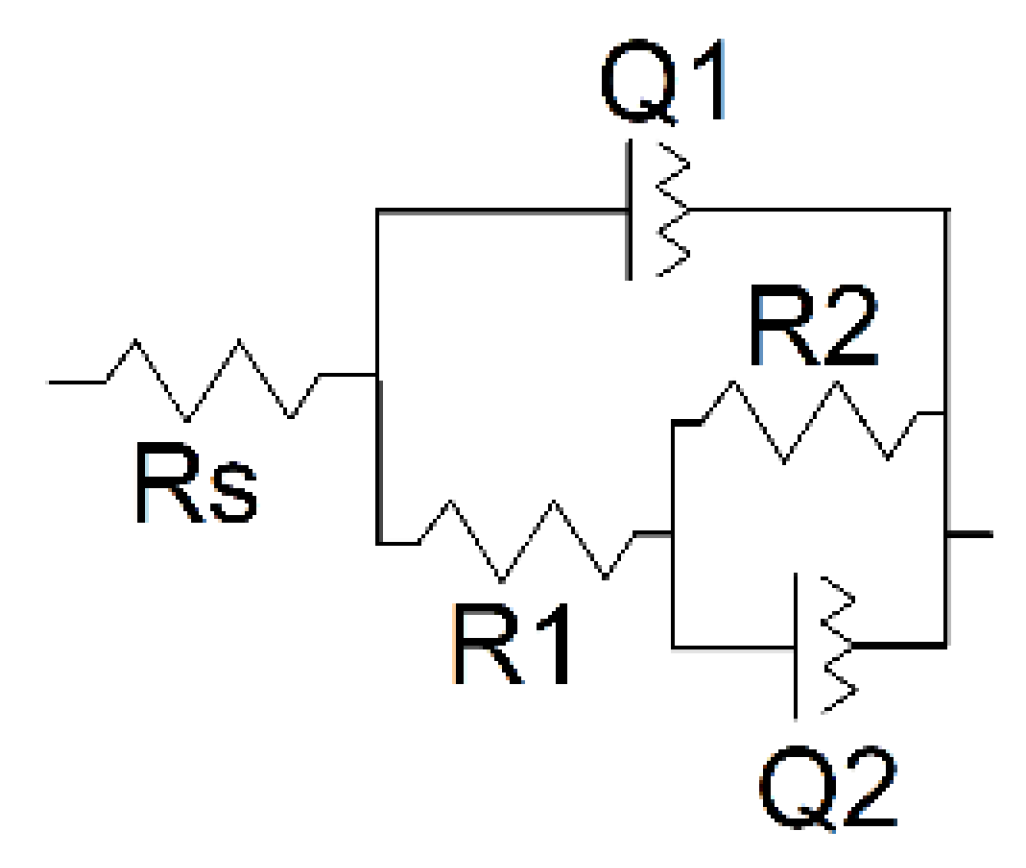
Three-electrode cells equipped with the glassy carbon electrode (GCE, 0.0167 cm2) Pt stripe as auxiliary electrode and Ag/AgCl/3 M KCl reference electrode was used for cyclic voltammetry (CV) and EIS measurements. In the EIS experiments, the potential frequency was varied from 100 kHz to 0.04 Hz, amplitude of the applied sine potential was equal to 5 mV, and equilibrium potential was calculated as a half-sum of the peak potentials recorded in a 0.01 M [Fe(CN)6]3−/4− pair as the redox probe. Measurements were performed in 0.1 M phosphate buffer containing 0.1 M NaNO3. The impedance parameters were calculated from the Nyquist diagram corresponding to the R(RC)(RC) equivalent circuit using NOVA software (Metrohm Autolab b.v., Utrecht, Netherlands).
Electrochemical quartz crystal microbalance (EQCM) measurements were performed with the EQCM module of the CHI 440B instrument (CH Instruments, Inc. Austin, Texas, USA) equipped with the EQCM chip (basic frequency 8 MHz, 0.205 cm2) and Au thin-film electrodes.
Scanning electron microscopy (SEM) images of the electrode coatings were obtained with a Merlin™ (Carl Zeiss AG, Oberkochen, Germany) high-resolution field emission scanning electron microscope.
Atomic force spectroscopy (AFM) images of glassy carbon sheets covered with electropolymerized films were obtained with a Dimension FastScan (Bruker, Karlsruhe, Germany) scanning probe microscope in the mode of quantitative nanomechanical mapping using silicon probes “Bruker scanasyst air” (curvature radius ~2 nm) and k 0.4 N/m. Scan rate was equal to 1 Hz within a 256 × 256 window. Image processing was performed with the Gwyddion–Free SPM data analysis software.
2.3. Azure A Electropolymerization and DNA Sensor Assembling
Prior to the Azure A electropolymerization, the GCE electrode was mechanically polished and cleaned with acetone and deionized water. Next, it was electrochemically cleaned by repeated potential cycling in 0.1 M H2SO4 until the background current stabilized. After that, it was immersed in 5 mL of the working buffer containing 0.2 mM Azure A. In some experiments, phosphate buffer was saturated with chloroform, as described above. The potential of the electrode was multiply cycled between −0.6 and 1.2 V with a scan rate of 100 mV/s. The electrode was then washed with deionized water and working buffer and dried in air at ambient temperature for 20 min. Codeposition of poly(Azure A) and DNA was performed in a similar manner. DNA was added to the Azure A dissolved in phosphate buffer to its final concentration of 0.2 mg/mL. Native, thermally denatured, and oxidized DNA samples were tested in these experiments. Thermal denaturation was performed by heating the DNA stock solution for 30 min at 95 °C followed by sharp cooling in crushed ice for 5 min. Oxidatively damaged DNA was performed by its treatment with the mixture of 0.9 mL of 4 mM CuSO4 and 1.3 μL of 30% H2O2 for 1 h.
3. Results
3.1. Electropolymerization of Azure A from Its Aqueous Solution
Azure A is a phenothiazine dye with a sterically hindered amino group from one side of the phenothiazine core and primary amino group from the opposite side (Figure 1).

Figure 1.
Chemical structure of Azure A.
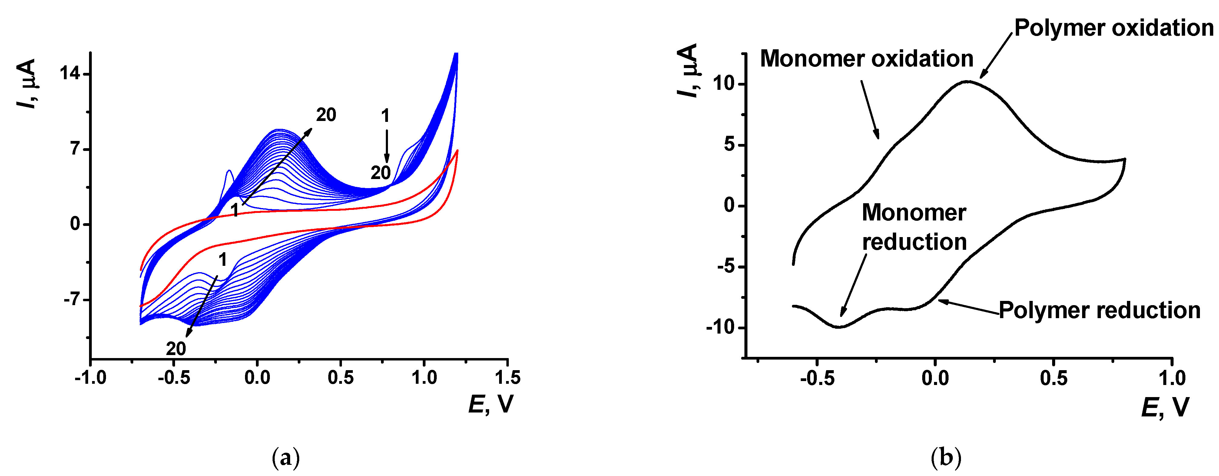
Electropolymerization of Azure A resulted in specific changes of the peaks on cyclic voltammograms (Figure 2) attributed to the deposition of redox active product on the electrode surface. At first scan, a pair of reversible redox peaks related to the redox conversion of the monomer appeared at about −0.17 and −0.22 V. In addition, an irreversible oxidation peak of the cation radical formation was found at high anodic potentials (about 0.9 V). In the following cycle of the potential, a new pair of the redox peaks shifted to higher anodic potentials (−0.13 and 0.14 V) against monomer peaks appeared and started growing (Figure 2a).
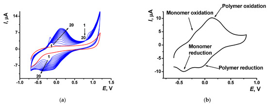
Figure 2.
(a) Multiple cyclic voltammograms recorded on the GCE in 0.1 M phosphate buffer containing 0.1 M NaNO3 and 0.2 mM Azure A, pH = 7.0; scan rate 100 mV/s. Red line corresponds to the bare GCE. Arrows indicate changes in the peaks from the 1st to 20th cycle. (b) Single cycle recorded on the GCE covered with poly(Azure A) transferred in the same buffer with no monomer dye.
Transferred to the working buffer with no monomer, the GCE modified with the poly(Azure A) demonstrated two pairs of the peaks on the cyclic voltammogram (Figure 2b). For structurally relative Azure B, similar peaks were referred to the polymer and the monomer entrapped in the growing polymer film [42]. Stability of the redox signals was assessed for six electrodes modified by means of the same set of reagents. In ten consecutive potential scans, changes in the redox peaks related to the poly(Azure A) were negligible, whereas the oxidation peak current of the monomeric dye decreased by 20% and that of the reduction peak current by 45%.
The slope of the bilogarithmic dependence of the peak current (Ip) on the scan rate (ν) indicated diffusion control of the monomer oxidation (d(logIp)/d(logν) = 0.44 ± 0.02) and mixed diffusion–adsorption control of the polymer conversion (0.84 ± 0.03 for oxidation peak current and 0.81 ± 0.03 for reduction peak current).
Variation of the pH influenced the signals of monomeric and polymeric forms of Azure A in a different manner (Figure S1, Supplementary Materials). Thus, oxidation peak current of the monomeric dye was stable in acidic media and decreased when transferred in the neutral and alkaline media. Oxidation peak current of the polymeric form regularly decreased in the pH range from 3.0 to 7.0. In alkaline solution, the signal became higher. The difference in the behavior of the monomer and polymer observed could be attributed to the alternative reaction of the dyes with dissolved oxygen and pH-dependent accessibility of the redox centers of the layer components toward this oxidant. The reduction peak current of the monomeric dye increased with pH in acidic and neutral media and reached a flat maximum at pH > 7.0. The appropriate peak of the polymeric form was pH independent.
Alternative chemical oxidation of reduced Azure A fragments by dissolved oxygen was confirmed by appropriate experiments performed after oxygen removal by the nitrogen (Figure S2, Supplementary Materials). Both anodic and cathodic peak currents increased against those recorded in the presence of oxygen. The effect is more pronounced in acidic media where the current shift was about 40%, while in neutral and basic media it was about 25% and did not significantly depend on the pH value. The shape and position of the peaks remained the same after the oxygen removal. Together with reproducibility of the peaks in a series of experiments performed with the same sensor, this means the nature of the products obtained in chemical and electrochemical oxidation is the same.
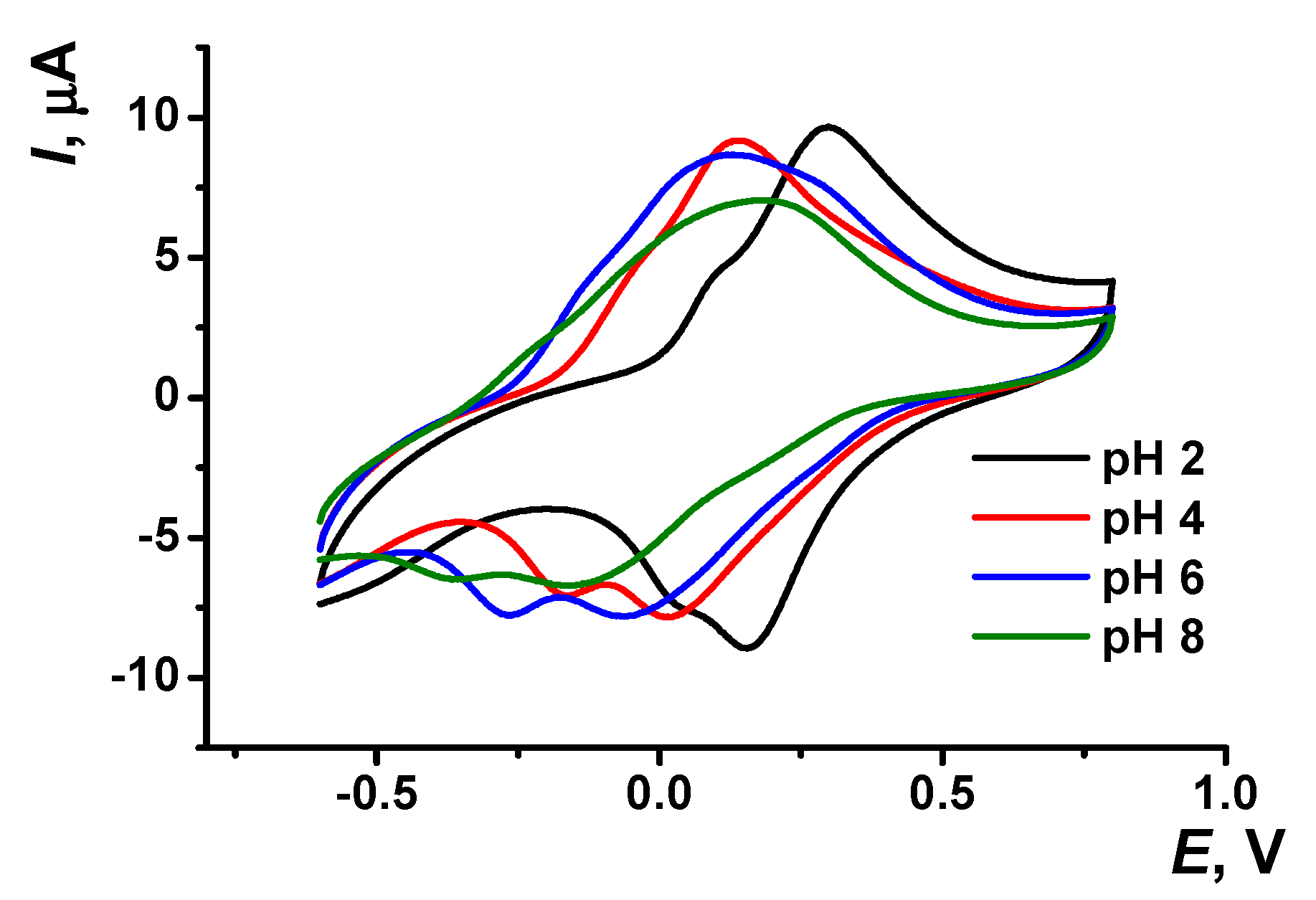
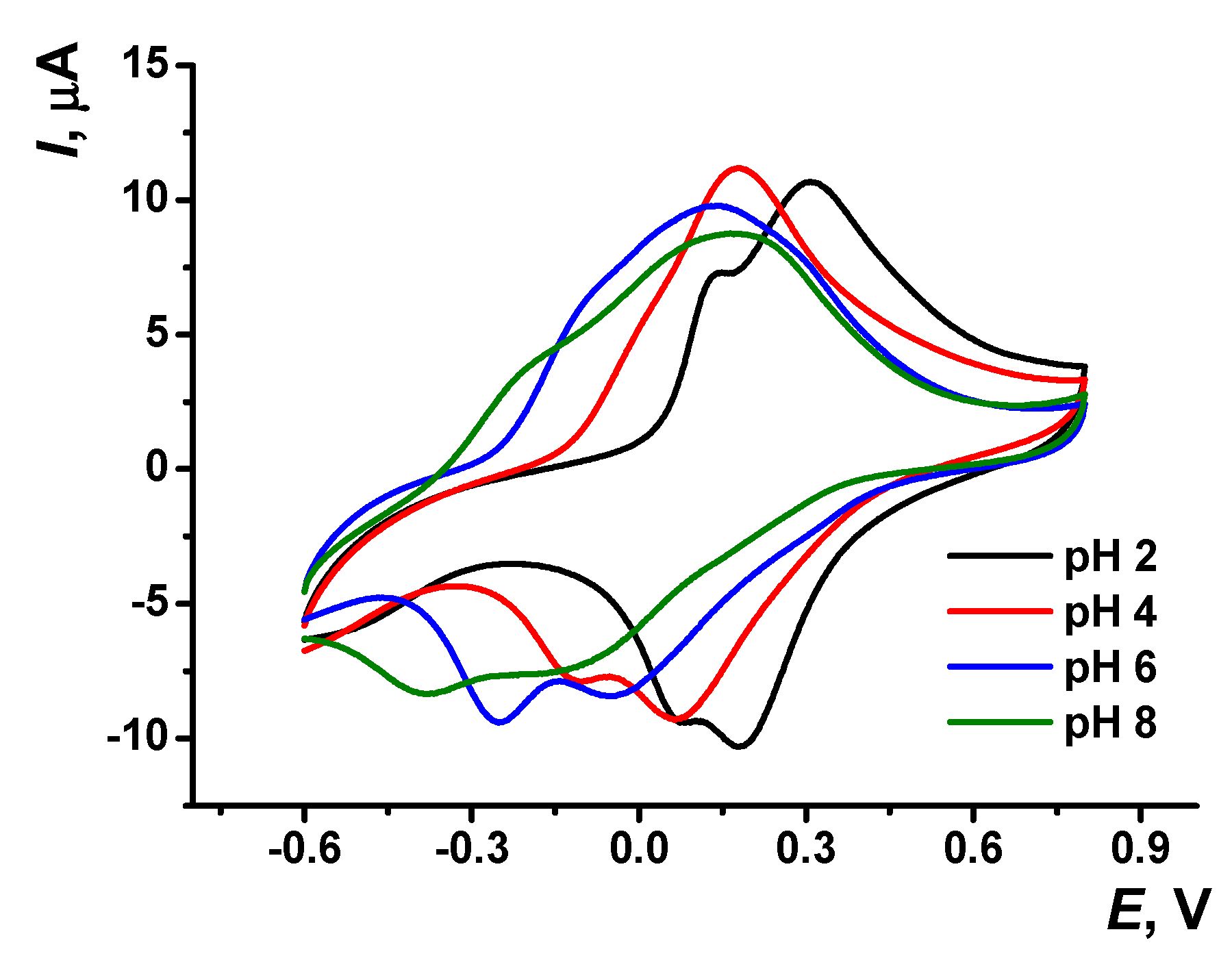
The pH dependency of voltammograms obtained with the GCE covered with poly(Azure A) in the working buffer with no monomer is illustrated in Figure 3. The peak currents are insignificantly decreasing with the pH increase. The effect is more pronounced in basic media and for cathodic peaks. Changes observed can be attributed to the influence of protonation–deprotonation within the polymer film on the electron exchange between reduced and oxidized forms of the dye, both in monomeric and polymeric forms.
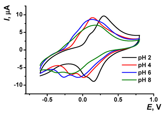
Figure 3.
Cyclic voltammogram recorded on the GCE modified with poly(Azure A) in 0.1 M phosphate buffer at different pH values; scan rate 100 mV/s.
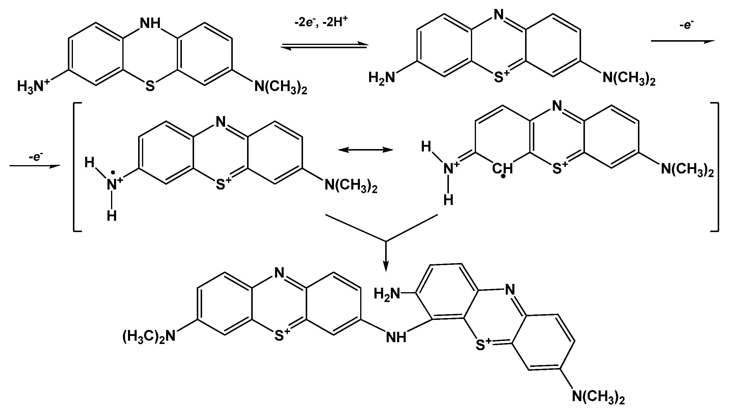
Both peak potentials of the polymer in acidic media (pH = 2.0–6.0) and anodic peak potential of the monomer depended linearly on the pH with the slope close to −59 mV/pH indicating equal number of the hydrogen ions and electrons transferred. This coincides well with the mechanism of Azure A electropolymerization proposed elsewhere for similar conditions of potential scanning [43]. An appropriate reaction scheme is presented in Figure 4. It involves the formation of cation radicals followed by their coupling and stabilization by hydrogen ion release.
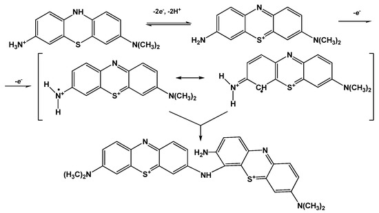
Figure 4.
Mechanism of Azure A electropolymerization.
The pH dependence of the reduction peak of the monomer showed a slope of −73 mV/pH. This can be related to the pH-dependent alternative reaction of the monomer oxidation with dissolved oxygen or pH-caused changes in the accessibility of the monomeric dye molecules toward electron exchange. It should be noted that the pH influence was quite reversible and appropriate peak positions could be restored by the opposite pH shift in the range studied (pH = 2.0–8.0). At higher pH, the polymer film becomes chemically instable, probably due to oxidative decomposition, so that the peaks on the voltammograms changed irregularly within the pH range studied.
3.2. Electropolymerization of Azure A in the Buffer Saturated with Chloroform
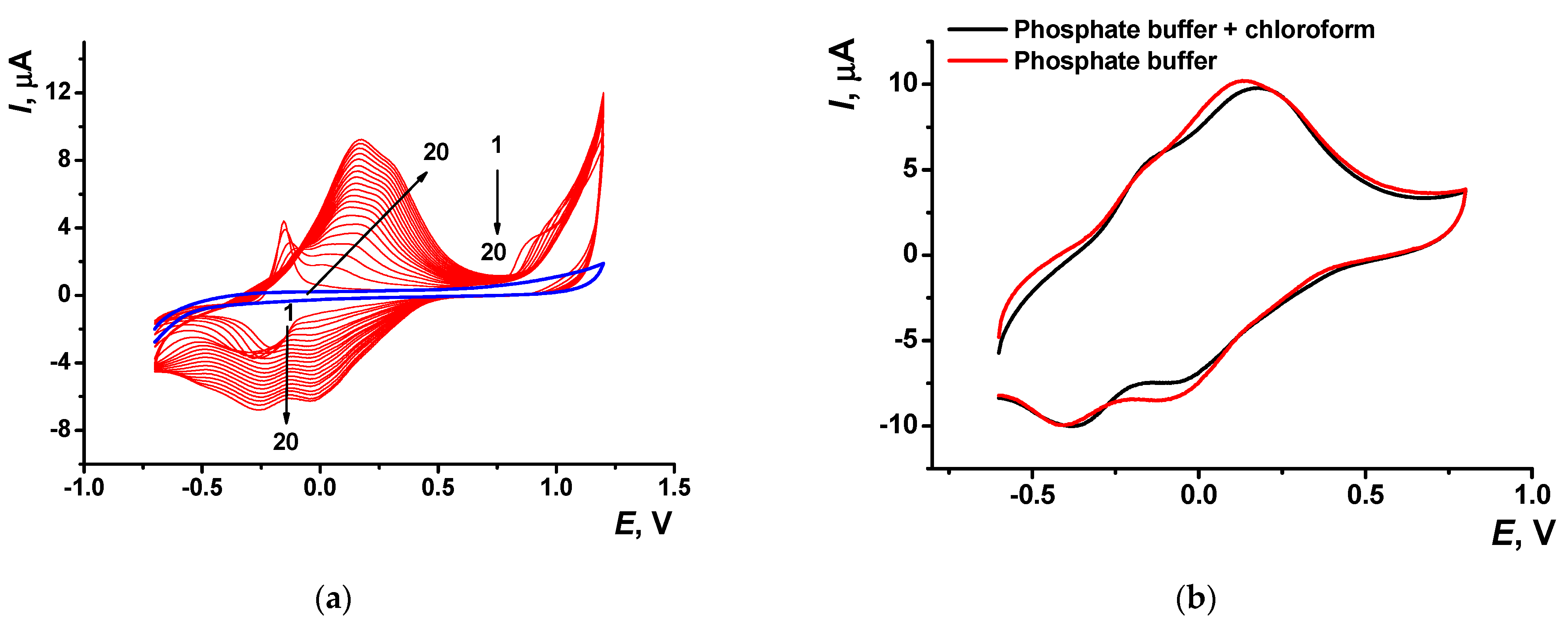
Deposition of the poly(Azure A) film from the phosphate buffer saturated with chloroform (denoted below as poly(Azyre A)/Chl) showed similar peaks on the voltammogram. The peak pairs related to the monomer were shifted to less cathodic potentials (−0.15 and −0.20 V) against those previously described in phosphate buffer with no solvent. Cathodic peaks on the reversed branch of cyclic voltammograms were much better resolved (Figure 5). Shape of the same peaks recorded in the absence of the monomer (Figure 5b) was less sensitive to the presence of organic solvent, assuming similar mechanism of the electrode reactions. Meanwhile, the stability of the polymeric film obtained in the presence of chloroform was higher than that of the film deposited in conventional conditions. The reduction peak of the polymer was stable for at least 10 consecutive scans of the potential, whereas anodic peak tended to decrease in the same series by 15%.
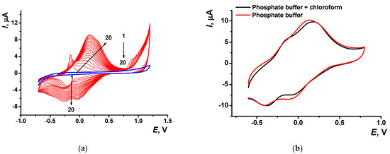
Figure 5.
(a) Multiple cyclic voltammograms recorded on the GCE in 0.1 M phosphate buffer containing 0.1 M NaNO3 and 0.2 mM Azure A and saturated with chloroform, pH = 7.0; scan rate 100 mV/s. Arrows indicate changes in the peaks from the 1st to 20th cycle, blue line corresponds to bare GCE. (b) Single cycle recorded on the GCE covered with poly(Azure A) transferred in the same buffer with no monomer dye.
In accordance with the dependence of the peak currents on the scan rate, redox conversion of the monomeric dye was controlled by diffusion (d(logIp)/d(logν) = 0.53 ± 0.01 and 0.40 ± 0.02 for oxidation and reduction, respectively) whereas polymeric dye showed mixed (adsorption–diffusion) control (d(logIp)/d(logν) = 0.80 ± 0.01 and 0.85 ± 0.02).
The pH dependence of the peak parameters on voltammograms recorded in the Azure A solution saturated with chloroform are presented in Figure S3, Supplementary Materials. In comparison with the peaks recorded in absence of organic solvent, monomer peak currents were higher and those of the polymer coatings slightly lower.
Cyclic voltammograms recorded on the GCE modified with poly(Azure A)/Chl in the absence of the monomeric dye in solution are presented in Figure 6. As in the case of poly(Azure A), the peaks of the poly(Azure A)/Chl shifted to more cathodic potentials with increasing pH values. The parameters of the Ep–pH dependencies are summarized in Table S1. The slope of the Ep–pH dependence mostly corresponded to the equal number of the H+ ions and electrons transferred (−57 ± 2 mV/pH for the monomer oxidation, −60 ± 0.4 mV/pH and −58 ± 0.3 mV/pH for the polymer oxidation and reduction). The slope of the pH dependence of the monomer reduction peak was significantly higher (−83 ± 0.3 mV/pH). The linearity of appropriate dependencies was broader than that of the poly(Azure A) and covered the range of pH = 2.0–7.0.
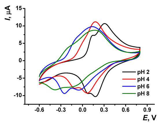
Figure 6.
Cyclic voltammograms recorded on GCE covered with poly(Azure A/Chl), 0.1 M phosphate buffer containing 0.1 M NaNO3; scan rate 100 mV/s.
3.3. DNA Implementation in Surface Layers
Implementation of DNA into the redox active polymer layer is commonly performed by drop casting of the DNA solution [40] or addition of the DNA to the reaction media on the electropolymerization stage [14,44]. Adsorption of native DNA added to the monomer solution within the electropolymerization process led to the decrease of the currents on voltammograms. Thermal denaturing and chemical oxidation of the DNA molecules with reactive oxygen species further suppressed the currents recorded. Typical voltammograms are presented in Figure S3, Supplementary Materials.
3.3.1. EQCM Measurements
The influence of the DNA addition to the Azure A electropolymerization was confirmed by EQCM measurements. The frequency of the quartz oscillation depends on the mass deposited onto the electrode surface, in accordance with Sauerbrey Equation (1) [45].
where Δf is the shift of the quartz resonance frequency, A the area of Au electrodes, ρq the quartz density, μq shear modulus, f0 fundamental resonance frequency of the quartz crystal, Cf the sensitivity coefficient, and Δm the surface mass change. Although Equation (1) describes the deposition of the mass on the QCM surface in dry conditions, proportionality of the frequency change to the mass deposited retained in liquids, although the sensitivity of this dependency is about one half [46].
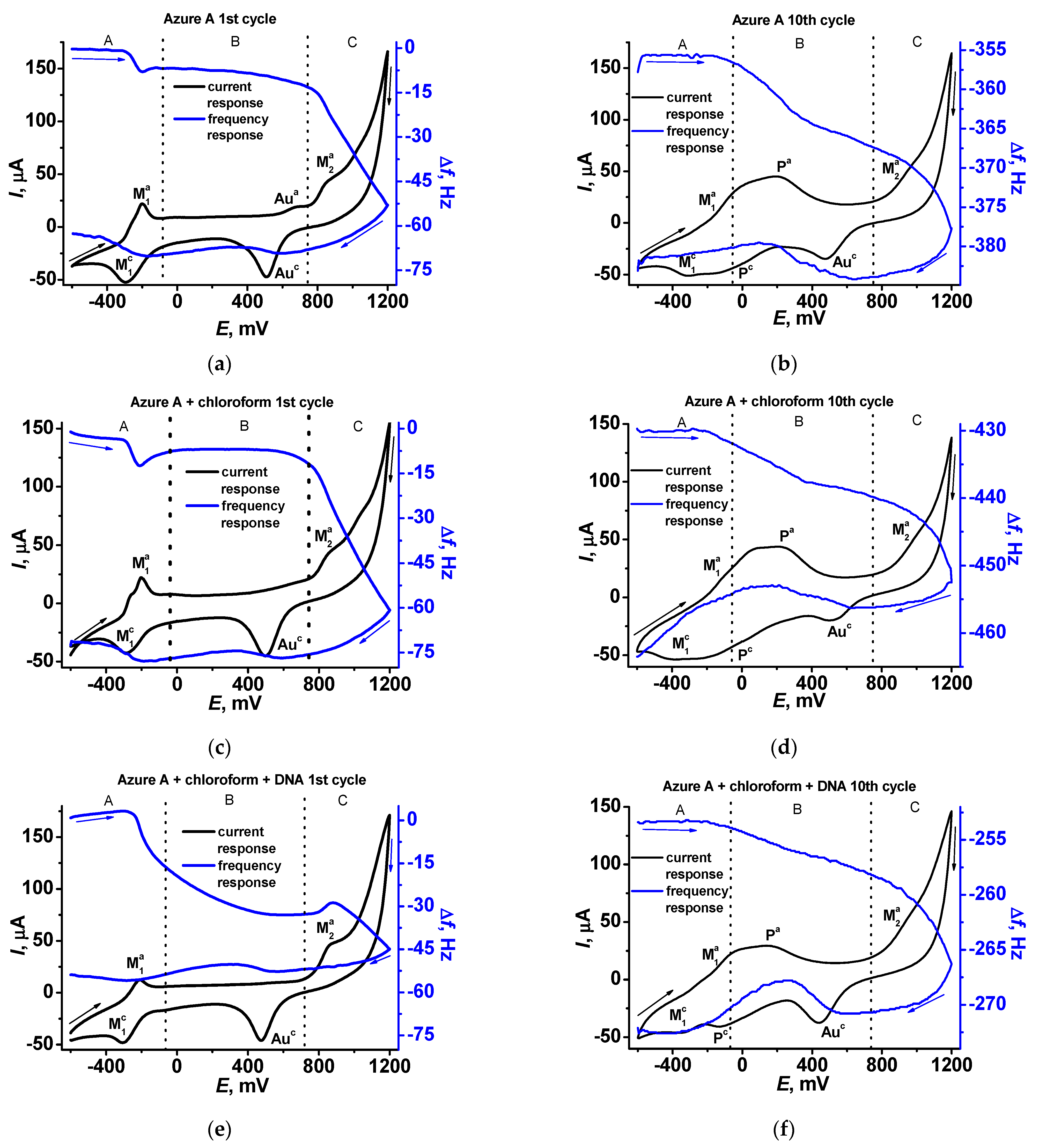
In Figure 7, cyclic voltammograms and sensograms are presented for the first (Figure 7a,c,e) and tenth (Figure 7b,d,f) cycles of the potential scanning. In the first scan, well-resolved peaks of the monomeric form (anodic and cathodic peaks M in the A area of the potentials) are present on the cyclic voltammogram together with an irreversible anodic peak initiating polymerization in the C area. Sensograms indicate adsorption of the oxidized form and desorption of the reduced forms of the dye in the A area, which correspond to appropriate shifts of the frequency. In the B area, insignificant changes of the resonance frequency can be found in the absence of DNA, except for a small decrease related to the gold oxidation. In the presence of the DNA, the mass deposited in the B area increases due to electrostatic accumulation of the DNA molecules. In the C area, frequency significantly decreases due to formation of the polymeric form of the dye. It should be noted that DNA adsorbed in the B area negatively affects the polymer deposition due to partial blocking of the electrode surface. The morphology of the sensograms exert a negative trend due to continuing accumulation of the polymer film to the tenth potential scan (Figure 7b,d,f). On voltammograms recorded at the tenth scan, the signals related to the polymer form of the dye appeared (P signals in the A and B areas), indicating redox activity of the film. Meanwhile, the response of the monomeric forms retains conversion to the waves because of the overlapping signal.
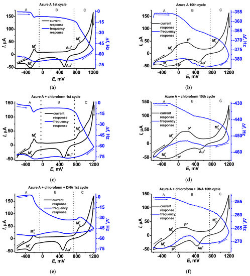
Figure 7.
Cyclic voltammograms (black) and sensograms (blue) recorded on the QCM chip in 0.1 M phosphate buffer containing 0.1 M NaNO3, pH = 7.0 (a,b), in the presence of chloroform (c,d), and in the presence of chloroform and 0.2 mg/mL DNA (e,f).
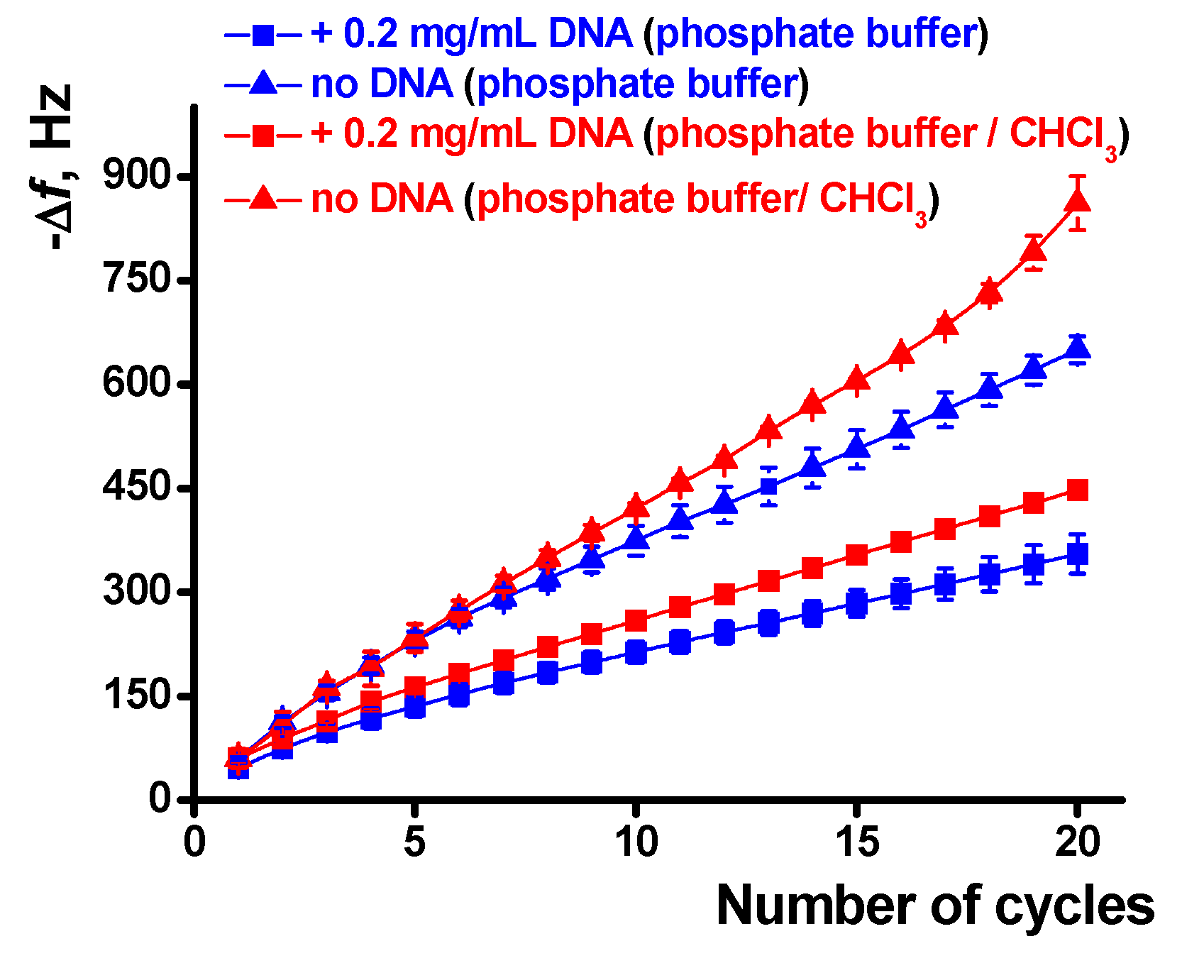
The influence of chloroform and DNA on the polymerization is quantified in Figure 8. The effect is well pronounced in the whole range of the potential scans and is higher for a large number of cycles and the experiments with the DNA addition. The results obtained are well reproducible and show deviation of the frequency change of about 3.5% for six independent EQCM chips modified with the same set of reagents.
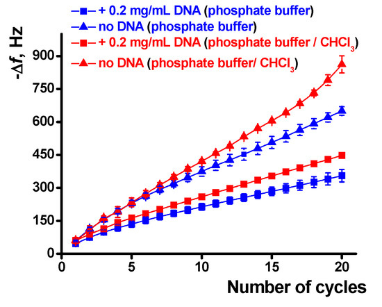
Figure 8.
Dependence of the EQCM frequency shift on the number of potential cycles during the poly(Azure A) electropolymerization, average from six QCM chip measurements.
It should also be noted that the concentration of the DNA shown in Figure 7 and Figure 8 corresponds to the maximal DNA influence. Lower quantities added do not significantly alter the EQCM parameters while larger ones result in significantly higher deviation of the signals. The increase in the number of potential scans that follow is complicated by lower reproducibility of the results, very long duration of the experiment, and occasional resonance quenching due to overloading of its surface.
3.3.2. Scanning Electron and Atomic Force Microscopy
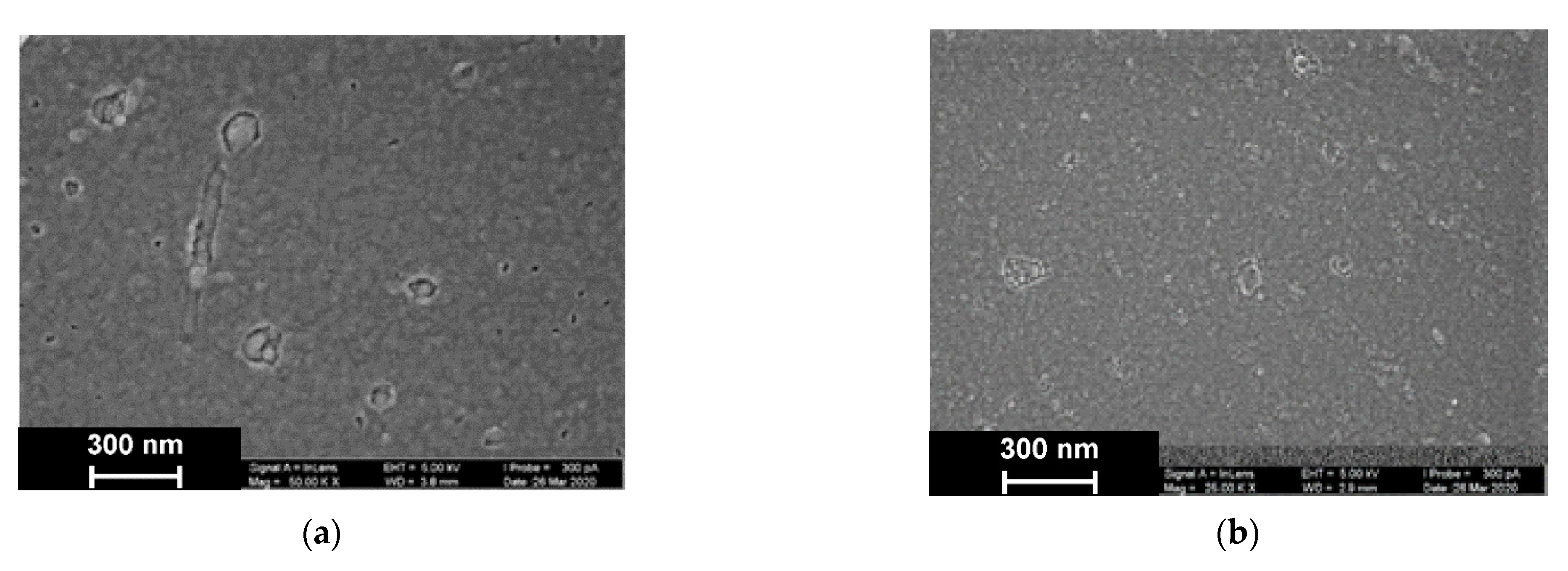
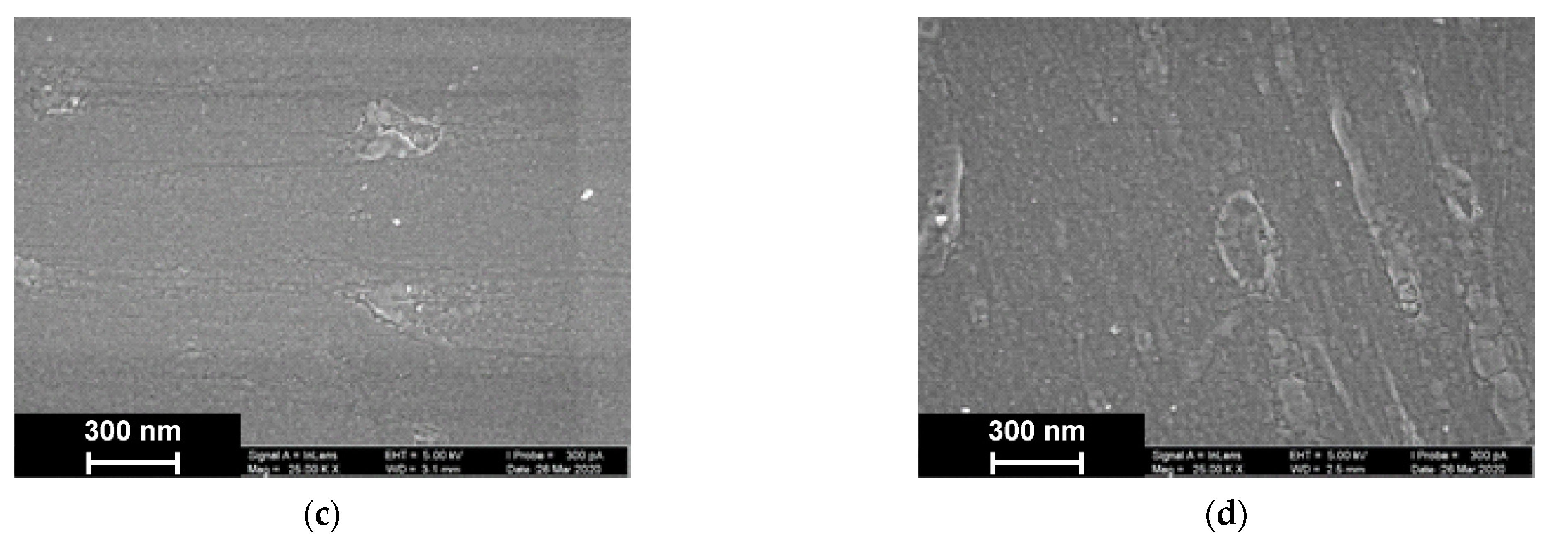
As was established by SEM, electropolymerization of Azure A results in formation of a uniform film with cellular pore structure and roundish defects appearing as dimples with an average diameter of about 40 nm (Figure 9).
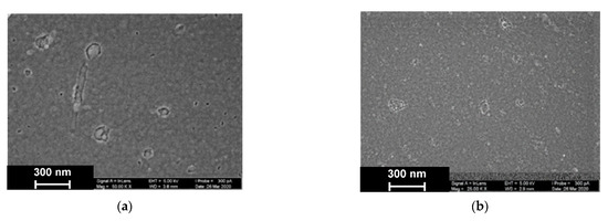
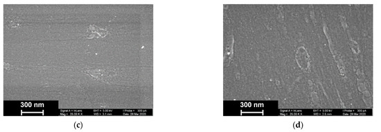
Figure 9.
SEM images of the GCE surface covered with Azure A electropolymerized from phosphate buffer (a,c), in the presence of 0.2 mg/mL DNA (b,d), and in the absence (a,b) and presence of CHCl3 (c,d). Twenty cycles of polymerization.
The addition of DNA to the monomer solution with no CHCl3 makes the layer denser. Additionally, a new kind of defect with spiral or roundish boundaries appeared with an average size of 70 nm. All types of defects with no respect to their size show internal fine crystalline structure. Similar images obtained in phosphate buffer saturated with chloroform indicated formation of the films with a more even surface and smaller domains, some of which were amalgamated in elongated structures.
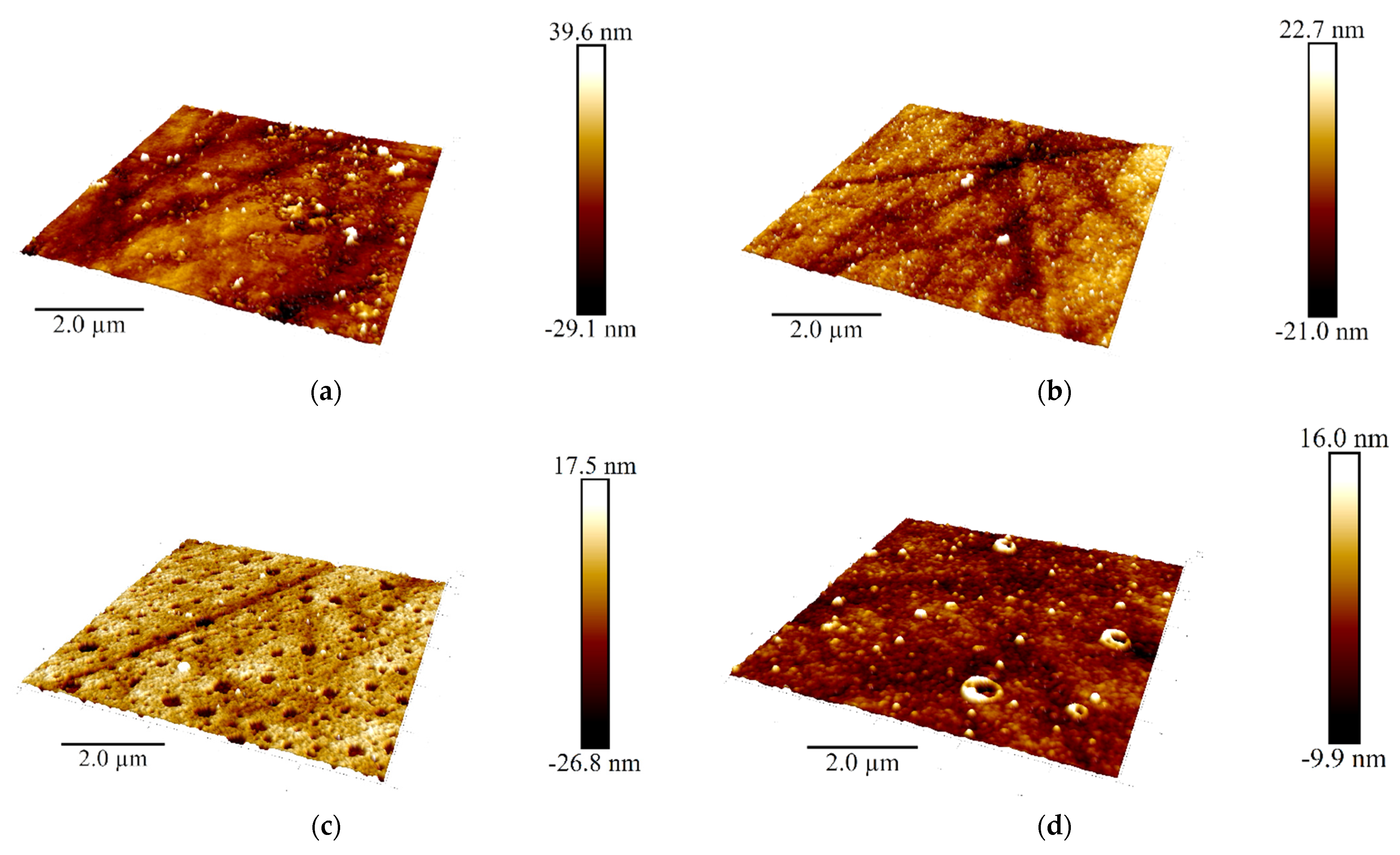
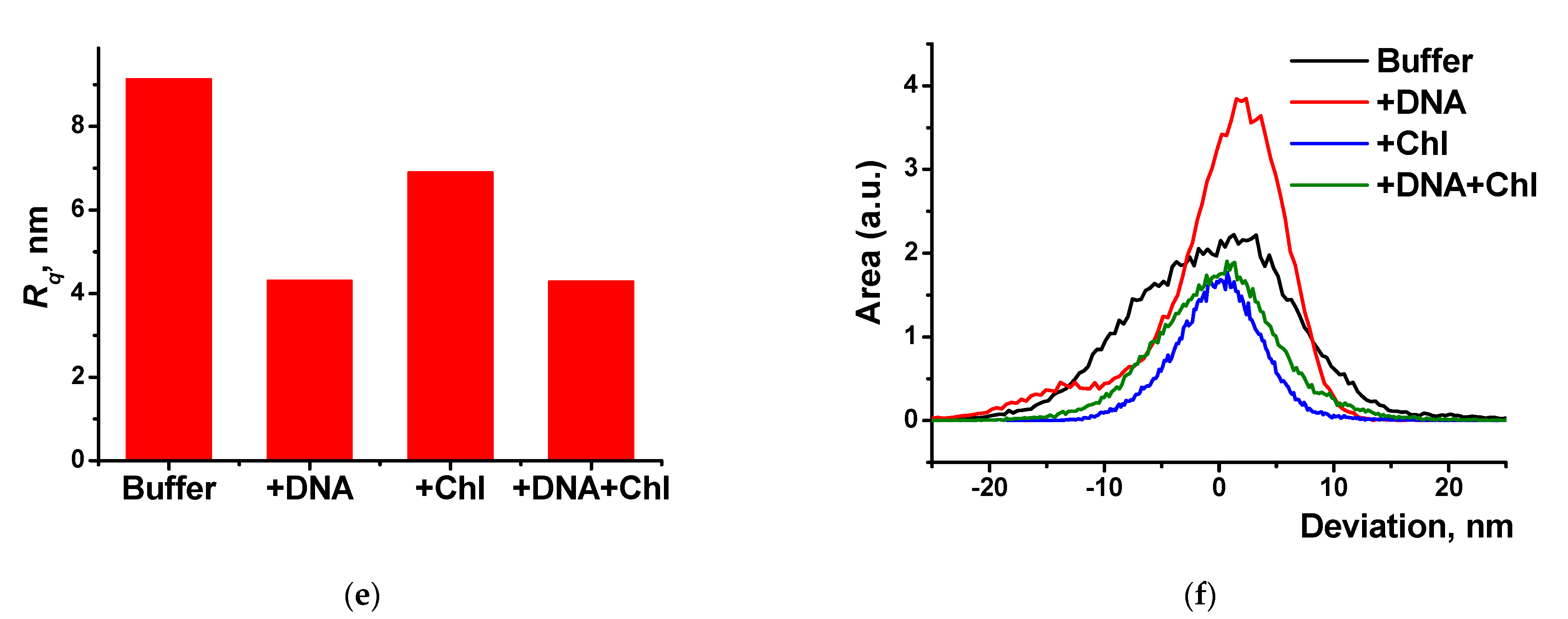
Additional information on the structure of the poly(Azure A) and poly(Azure A)/Chl films was obtained using AMF (Figure 10).
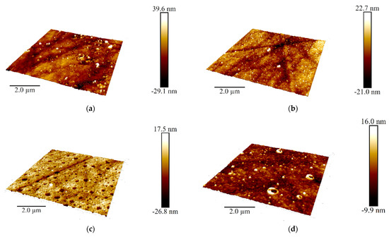
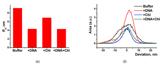
Figure 10.
AFM 3D models of the films on the GCE surface covered with Azure A electropolymerized from phosphate buffer (a,c), in the presence of 0.2 mg/mL DNA (b,d), and in the absence (a,b) and in the presence of CHCl3 (c,d); twenty cycles of polymerization. Root mean square values (e) and distribution of heights over the 10 × 10 μm2 region for the polymers deposited from the buffer and that with addition of DNA (+DNA), saturated with chloroform (+Chl), and that containing both DNA and chloroform (+DNA + Chl) (f).
DNA addition to the monomer solution decreased total roughness of the film surface and height deviation within the scan window. The number of peaks on the surface decreased, but their square became larger. In the presence of chloroform and absence of DNA, holes appeared in the film instead of peaks. Most interesting, they were decorated with a kind of oval embankment so that the height difference was maximal near the pores. Cross lines visible on all the AFM images belong to the scratches formed during mechanical polishing of the glassy carbon sheets used for AFM measurements. Probably, the formation of the holes can be related to the dissolution of a part of Azure A aggregates caused by organic solvent. Combination of electrostatic accumulation with negatively charged DNA and disaggregation of dye molecules resulted in formation of a more complex landscape in the case of simultaneous influence of chloroform and DNA on the electropolymerization stage.
3.3.3. Electrochemical Impedance Measurements
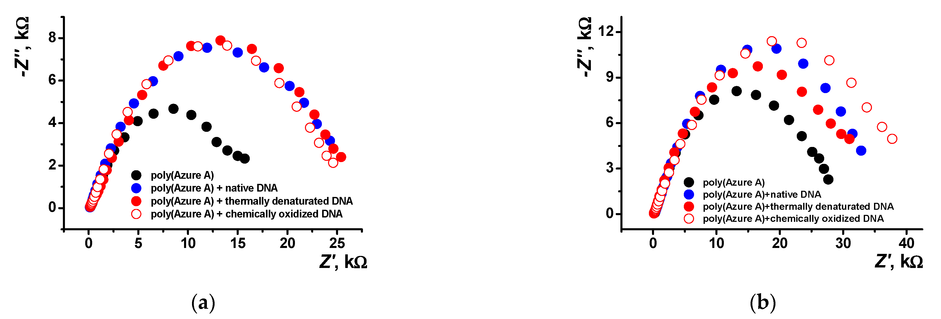
EIS is a powerful tool for electrochemical measurements that provides valuable information on the surface layer assembly and its influence on the electron transfer at the electrode interface. In this work, EIS measurements were made in an equimolar mixture of 0.01 M [Fe(CN)6]3− and [Fe(CN)6]4– ions as redox probe. Three types of DNA, i.e., native DNA, DNA chemically oxidized by the Cu2+/H2O2 mixture, and thermally denatured DNA, were tested. Mechanism and conditions for the model DNA damage were established elsewhere [15,47,48]. Figure 11 shows the Nyquist diagrams obtained with the layers obtained in various conditions. Bode diagram (frequency dependence of the phase angle) is presented in Figure S5 (Supplementary Materials) for various polymer coatings.
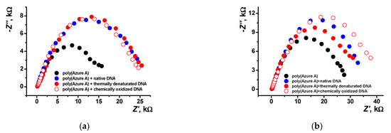
Figure 11.
Nyquist diagrams of the impedance spectra recorded on the GCE covered with poly(Azure A) with and without DNA addition for the film–solution interface: (a) electropolymerization from aqueous solution of 0.2 mM Azure A in 0.1 M phosphate buffer containing 0.1 M NaNO3 and 0.2 mg/mL DNA; (b) saturated with chloroform. Frequency range from 100 kHz to 0.04 Hz, amplitude of the applied sine potential 5 mV, pH = 7.0, and twenty cycles.
As seen in Figure 11b, the introduction of damaged DNA molecules in the growing polymer film increases the radius of the high frequency semicircle. This makes it possible to recognize DNA damaging factors in real sample assay.
Interpretation of the EIS data was made using the equivalent circuit earlier proposed for the electrode coated with the porous film (Figure 12) [49,50].
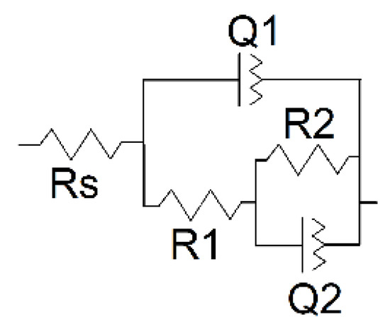
Figure 12.
Equivalent circuit for the assessment of EIS parameters.
Here, capacitance of the intact coating is represented by the constant phase element (CPE) Q1. R1 (pore resistance) is related to the ion conducting paths in the film formed in electropolymerization. The interface between the electrolyte in the internal film filling and the electrode is modeled by double-layer capacitance (CPE Q2) in parallel with a kinetically controlled charge-transfer reaction (R2). The exponent of the constant phase element (n) has been assessed from the Equation (2)
where Z is impedance, Q is the CPE, ω is angular frequency of a sinusoidal signal, and j2 = −1. The factor n is an adjustable parameter. When n differs from 1, the behavior of the system is mostly attributed to the surface heterogeneity [51]. When n = 1, the CPE represents an ideal capacitor. Here, n1 and n2 are related to the Q1 and Q2 CPE in equivalent circuit presented in Figure 12. The results of the EIS data fitting are presented in Table 1.

Table 1.
EIS parameters obtained for poly(Azure A)–DNA assembling in various conditions of DNA treatment (average ± S.D. for six electrodes).
Electropolymerization of Azure A in the presence of chloroform shows a lower n factor indicating higher porosity of the film. This coincides well with the AFM data. Deposition of the polymer in the presence of DNA makes the film smoother due to partial filling of the pores with the biopolymer molecules. As a result, factor n increases together with the R2 values. The charge transfer resistance R1 increases threefold after DNA entrapment. Damaged DNA molecules, being more flexible, decrease this parameter but do not significantly alter R2 values. The effect is less pronounced for the coating obtained in the presence of organic solvent because of higher pore dimensions and lower influence of the DNA molecules on the EIS parameters. Observation changes in the resistance makes it possible to distinguish DNA damaging factors.
4. Discussion
The results obtained showed significance of chloroform for the performance of the DNA sensor based on the Azure A polymerization products. Although the saturated buffer solution contained very small quantities of chloroform (0.8%), the polymer films obtained showed significant changes in their parameters important for sensing specific DNA reactions. In the presence of chloroform, the morphology of the surface layer was fully changed: instead of small peaks, regular pores were observed in the absence of DNA. Introduction of DNA in the reaction media containing organic solvent also affected the surface film by partial filling of one pore and unusual decoration of other pores with oval reeds. Although the surface was generally flattened, these changes increased adsorption capability of the polymer, as followed from the SEM/AFM experiments. The effect of chloroform can be explained by partial disaggregation of the monomeric dye molecules onto the growing polymer film and by changes in the hydrophilicity of the surface important for the interactions with the DNA molecules. The efficiency of electropolymerization controlled by the mass changes confirmed the positive effect of chloroform on the deposition of the polymeric form of the dye, both in the absence of DNA and together with the entrapped biopolymer. The mechanism of chloroform influence coincides well with the results of EIS assessment of the capacity and charge transfer resistance that reflect charge separation and efficiency of the ferri-/ferrocyanide transfer through the polymeric film. The advantages of possible application of the DNA sensor developed are shown in the example of discrimination of native and thermally and chemically damaged DNA by their influence on the EIS parameters. Being negligible for traditional electropolymerization, they demonstrated remarkable difference in the case of the coating deposited in the presence of chloroform. This offers new opportunities for the design of electrochemical DNA sensors that can be used in extreme media, including organic solvents, and for providing reliable information on the biochemical interactions with DNA implemented in the surface layer.
Supplementary Materials
The following are available online at https://www.mdpi.com/article/10.3390/s21092949/s1, Figure S1: The pH dependence of the anodic and cathodic peak currents of the monomer and polymer of poly(Azure A); Figure S2: Cyclic voltammograms recorded on the GCE covered with poly(Azure A) in the presence of dissolved oxygen and after its removal; Figure S3: The pH dependence of the anodic and cathodic peak currents of the monomer and polymer of poly(Azure A) saturated with chloroform; Figure S4: Cyclic voltammograms recorded on GCE in 0.1 M phosphate buffer containing 0.1 M NaNO3 and that saturated with chloroform in the presence of 0.2 mM Azure A and 0.2 mg/mL native and thermally denatured and chemically oxidized DNA. Figure S5: The dependence of the phase angle (φ, °) on the potential frequency obtained with the GCE covered with poly(Azure A) in various conditions. Table S1: The pH dependence of the peak potential of the poly(Azure A) film obtained on GCE.
Author Contributions
Conceptualization, G.E.; methodology, A.P. and G.E.; investigation, V.E., Y.K., A.P., and K.P.; writing—original draft preparation, G.E.; writing—review and editing, G.E. All authors have read and agreed to the published version of the manuscript.
Funding
This research was funded by Russian Science Foundation, grant number 17-73-20024.
Institutional Review Board Statement
Not applicable.
Informed Consent Statement
Not applicable.
Data Availability Statement
No data applicable.
Acknowledgments
SEM and AFM investigation was performed in the Interdisciplinary Center of Analytical Microscopy of Kazan Federal University.
Conflicts of Interest
The authors declare no conflict of interest.
References
- Nejadmansouri, M.; Majdinasab, M.; Nunes, G.S.; Marty, J.L. An overview of optical and electrochemical sensors and biosensors for analysis of antioxidants in food during the last 5 years. Sensors 2021, 21, 1176. [Google Scholar] [CrossRef]
- Baracu, A.M.; Gugoasa, L.A.D. Review—recent advances in microfabrication, design and applications of amperometric sensors and biosensors. J. Electrochem. Soc. 2021, 168, 037503. [Google Scholar] [CrossRef]
- Ozcelikay, G.; Karadurmus, L.; Kaya, S.I.; Bakirhan, N.K.; Ozkan, S.A. A review: New trends in electrode systems for sensitive drug and biomolecule analysis. Crit. Rev. Anal. Chem. 2020, 50, 212–225. [Google Scholar] [CrossRef] [PubMed]
- De Araujoa, W.R.; Cardoso, T.M.G.; da Rocha, R.G.; Santana, M.H.P.; Muñoz, R.A.A.; Richter, E.M.; Paixão, T.L.C.; Coltro, W.K.T. Portable analytical platforms for forensic chemistry: A review. Anal. Chim. Acta 2018, 1034, 1–21. [Google Scholar] [CrossRef] [PubMed]
- Arduini, F.; Cinti, S.; Scognamiglio, V.; Moscone, D.; Palleschi, G. How cutting-edge technologies impact the design of electrochemical (bio)sensors for environmental analysis. A review. Anal. Chem. Acta 2017, 59, 15–42. [Google Scholar] [CrossRef] [PubMed]
- Coluccio, M.L.; Pullano, S.A.; Vismara, M.F.M.; Coppedè, N.; Perozziello, G.; Candeloro, P.; Gentile, F.; Malara, N. Emerging designs of electronic devices in biomedicine. Micromachines 2020, 11, 123. [Google Scholar] [CrossRef] [PubMed]
- Nayak, S.; Blumenfeld, N.R.; Laksanasopin, T.; Sia, S.K. Point-of-care diagnostics: Recent developments in a connected age. Anal. Chem. 2017, 89, 102–123. [Google Scholar] [CrossRef]
- Tate, J.; Ward, G. Interferences in immunoassay. Clin. Biochem. Rev. 2004, 25, 105–120. [Google Scholar]
- Wang, C.-F.; Sun, X.-Y.; Su, M.; Wang, Y.-P.; Lv, Y.-K. Electrochemical biosensors based on antibody, nucleic acid and enzyme functionalized graphene for the detection of disease-related biomolecules. Analyst 2020, 145, 1550–1562. [Google Scholar] [CrossRef]
- Asal, M.; Özen, Ö.; Sahinler, M.; Polatoğlu, I. Recent developments in enzyme, DNA and immuno-based biosensors. Sensors 2018, 18, 1924. [Google Scholar] [CrossRef]
- Porfireva, A.; Hianik, T.; Evtugyn, G. Electrochemical DNA sensors based on nanostructured polymeric materials for determination of antitumor drugs. In Macro, Micro and Nano-Biosensors. Potential Applications and Possible Limitations; Rai, M., Reshetilov, A., Plekhanova, Y., Ingle, A.P., Eds.; Springer Nature: Cham, Switzerland, 2021; pp. 193–212. [Google Scholar] [CrossRef]
- Campuzano, S.; Pedrero, M.; Pingarrón, J.M. Electrochemical nucleic acid based biosensing of drugs of abuse and pharmaceuticals. Curr. Med. Chem. 2018, 25, 4102–4118. [Google Scholar] [CrossRef]
- Lima, H.R.; Silva, J.S.; De Farias, E.A.O.; Teixeira, P.R.S.; Eiras, C.; Nunes, L.C.C. Electrochemical sensors and biosensors for the analysis of antineoplastic drugs. Biosens. Bioelectron. 2018, 108, 27–37. [Google Scholar] [CrossRef] [PubMed]
- De la Cruz Morales, K.; Alarcón-Angeles, G.; Merkoçi, A. Nanomaterial-based sensors for the study of DNA interaction with drugs. Electroanalysis 2019, 31, 1845–1867. [Google Scholar] [CrossRef]
- Kuzin, Y.; Kappo, D.; Porfireva, A.; Shurpik, D.; Stoikov, I.; Evtugyn, G.; Hianik, T. Electrochemical DNA sensor based on carbon black-poly(neutral red) composite for detection of oxidative DNA damage. Sensors 2018, 18, 3489. [Google Scholar] [CrossRef] [PubMed]
- Ye, Y.; Ji, J.; Sun, Z.; Shen, P.; Sun, X. Recent advances in electrochemical biosensors for antioxidant analysis in foodstuff. TrAC-Trends Anal. Chem. 2020, 122, 115718. [Google Scholar] [CrossRef]
- Uzunboy, S.; Çekiç, S.D.; Eksin, E.; Erdemb, A.; Apak, R. CUPRAC colorimetric and electroanalytical methods determining antioxidant activity based on prevention of oxidative DNA damage. Anal. Biochem. 2017, 518, 69–77. [Google Scholar] [CrossRef]
- Öndeş, B.; Muti, M. Electrochemical determination of the effect of caffeic acid onto the interaction between idarubicin and DNA by single-use disposable electrodes. Electroanalysis 2020, 32, 1288–1296. [Google Scholar] [CrossRef]
- Phopin, K.; Tantimongcolwat, T. Pesticide aptasensors-sate of the art and perspectives. Sensors 2020, 20, 6809. [Google Scholar] [CrossRef]
- Topkaya, S.N.; Cetina, A.E. Electrochemical aptasensors for biological and chemical analyte detection. Electroanalysis 2021, 33, 277–291. [Google Scholar] [CrossRef]
- Villalonga, A.; Pérez-Calabuig, A.-M.; Villalonga, R. Electrochemical biosensors based on nucleic acid aptamers. Anal. Bioanal. Chem. 2020, 412, 55–72. [Google Scholar] [CrossRef]
- Goud, K.Y.; Reddy, K.K.; Satyanarayana, M.; Kummari, S.; Gobi, K.V. A review on recent developments in optical and electrochemical aptamer-based assays for mycotoxins using advanced nanomaterials. Microchim. Acta 2020, 187, 29. [Google Scholar] [CrossRef] [PubMed]
- Li, Z.; Mohamed, M.A.; Mohan, A.M.V.; Zhu, Z.; Sharma, V.; Mishra, G.K.; Mishra, R.K. Application of electrochemical aptasensors toward clinical diagnostics, food, and environmental monitoring: Review. Sensors 2019, 19, 5435. [Google Scholar] [CrossRef] [PubMed]
- Li, F.; Yu, Z.; Han, X.; Lai, R.Y. Electrochemical aptamer-based sensors for food and water analysis: A review. Anal. Chim. Acta 2019, 1051, 1–23. [Google Scholar] [CrossRef] [PubMed]
- Park, K.S. Nucleic acid aptamer-based methods for diagnosis of infections. Biosens. Bioelectron. 2018, 102, 179–188. [Google Scholar] [CrossRef] [PubMed]
- Bertok, D.; Lorencova, L.; Chocholova, E.; Jane, E.; Vikartovska, A.; Kasak, P.; Tkac, J. Electrochemical impedance spectroscopy based biosensors: Mechanistic principles, analytical examples and challenges towards commercialization for assays of protein cancer biomarkers. ChemElectroChem 2019, 6, 989–1003. [Google Scholar] [CrossRef]
- Poghossian, A.; Schöning, M.J. Capacitive field-effect EIS chemical sensors and biosensors: A status report. Sensors 2020, 20, 5639. [Google Scholar] [CrossRef]
- Peng, H.; Zhang, L.; Soeller, C.; Travas-Sejdic, J. Conducting polymers for electrochemical DNA sensing. Biomaterials 2009, 30, 2132–2148. [Google Scholar] [CrossRef]
- Evtugyn, G.; Hianik, T. Electrochemical DNA sensors and aptasensors based on electropolymerized materials and polyelectrolyte complexes. TrAC-Trends. Anal. Chem. 2016, 79, 168–178. [Google Scholar] [CrossRef]
- Mohamad, F.S.; Zaid, M.H.M.; Abdullah, J.; Zawawi, R.M.; Lim, H.N.; Sulaiman, Y.; Rahman, N.A. Synthesis and characterization of polyaniline/graphene composite nanofiber and its application as an electrochemical DNA biosensor for the detection of Mycobacterium tuberculosis. Sensors 2017, 17, 2789. [Google Scholar] [CrossRef] [PubMed]
- Wang, J.; Li, Y.; Li, C.; Zeng, X.; Tang, W.; Chen, X. A voltammetric study on the interaction between isoproterenol and cardiomyocyte DNA by using a glassy carbon electrode modified with carbon nanotubes, polyaniline and gold nanoparticles. Microchim. Acta 2017, 184, 2999–3006. [Google Scholar] [CrossRef]
- Tran, L.T.; Tran, H.V.; Dang, H.T.M.; Huynh, C.D.; Mai, T.A. Silver nanoparticles decorated polyaniline nanowires-based electrochemical DNA sensor: Two-step electrochemical synthesis. J. Electrochem. Soc. 2020, 167, 087508. [Google Scholar] [CrossRef]
- Shoaie, N.; Daneshpour, M.; Azimzadeh, M.; Mahshid, S.; Khoshfetrat, S.M.; Jahanpeyma, F.; Gholaminejad, A.; Omidfar, K.; Foruzandeh, F. Electrochemical sensors and biosensors based on the use of polyaniline and its nanocomposites: A review on recent advances. Microchim. Acta 2019, 186, 465. [Google Scholar] [CrossRef]
- Kulikova, T.; Porfireva, A.; Evtugyn, G.; Hianik, T. Electrochemical DNA sensors with layered polyaniline-DNA coating for detection of specific DNA interactions. Sensors 2019, 19, 469. [Google Scholar] [CrossRef]
- Khodadadi, A.; Faghih-Mirzaei, E.; Karimi-Maleh, H.; Abbaspourrad, A.; Agarwal, S.; Gupta, V.K. A new epirubicin biosensor based on amplifying DNA interactions with polypyrrole and nitrogen-doped reduced graphene: Experimental and docking theoretical investigations. Sens. Actuators B 2019, 284, 568–574. [Google Scholar] [CrossRef]
- Jain, R.; Jadon, N.; Pawaiy, A. Polypyrrole based next generation electrochemical sensors and biosensors: A review. TrAC-Trends Anal. Chem. 2017, 97, 363–373. [Google Scholar] [CrossRef]
- Booth, M.A.; Harbison, S.A.; Travas-Sejdic, J. Development of an electrochemical polypyrrole-based DNA sensor and subsequent studies on the effects of probe and target length on performance. Biosens. Bioelectron. 2011, 28, 362–367. [Google Scholar] [CrossRef] [PubMed]
- Rahman, M.M.; Lopa, N.S.; Kim, Y.J.; Choi, D.-K.; Lee, J.-J. Label-free DNA hybridization detection by poly(thionine)-gold nanocomposite on indium tin oxide electrode. J. Electrochem. Soc. 2016, 163, B153–B157. [Google Scholar] [CrossRef]
- Zhang, K.; Zhang, Y. Lable-free electrochemical DNA sensor based on gold nanoparticles/poly(neutral red) modified electrode. Electroanalysis 2010, 22, 673–679. [Google Scholar] [CrossRef]
- Porfireva, A.V.; Goida, A.I.; Rogov, A.M.; Evtugyn, G.A. Impedimetric DNA sensor based on poly(proflavine) for determination of anthracycline drugs. Electroanalysis 2020, 32, 827–834. [Google Scholar] [CrossRef]
- Porfireva, A.; Vorobev, V.; Babkina, S.; Evtugyn, G. Electrochemical sensor based on poly(Azure B)-DNA composite for doxorubicin determination. Sensors 2019, 19, 2085. [Google Scholar] [CrossRef] [PubMed]
- Sha, Y.; Gao, Q.; Qi, B.; Yang, X. Electropolymerization of Azure B on a screen-printed carbon electrode and its application to the determination of NADH in a flow injection analysis system. Microchim. Acta 2004, 148, 335–341. [Google Scholar] [CrossRef]
- Blacha-Grzechnik, A.; Piwowara, K.; Zdyba, T.; Krzywiecki, M. Formation of poly(Azure A)-C60 photoactive layer as a novel approach in the heterogeneous photogeneration of singlet oxygen. Appl. Surf. Sci. 2018, 457, 221–228. [Google Scholar] [CrossRef]
- Kulikova, T.N.; Porfireva, A.V.; Shamagsumova, R.V.; Evtugyn, G.A. Voltammetric sensor with replaceable polyaniline-DNA layer for doxorubicin determination. Electroanalysis 2018, 30, 2284–2292. [Google Scholar] [CrossRef]
- Sauerbrey, G.H. Verwendung von Schwingquarzen zur Wägung dünner Schichten und zur Mikrowägung. Z. Phys. 1959, 155, 206–222. [Google Scholar] [CrossRef]
- Kanazawa, K.K.; Gordon, J.G. Frequency of a quartz microbalance in contact with liquid. Anal. Chem. 1985, 57, 1770–1771. [Google Scholar] [CrossRef]
- Stoewe, R.; Prütz, W.A. Copper-catalyzed DNA damage by ascorbate and hydrogen peroxide: Kinetics and yield. Free Radic. Biol. Med. 1987, 3, 97–105. [Google Scholar] [CrossRef]
- Kuzin, Y.; Ivanov, A.; Evtugyn, G.; Hianik, T. Voltammetric detection of oxidative DNA damage based on interactions between polymeric dyes and DNA. Electroanalysis 2016, 28, 2956–2964. [Google Scholar] [CrossRef]
- Bierwagen, G.; Tallman, D.; Li, J.; He, L.; Jeffcoate, C. EIS studies of coated metals in accelerated exposure. Progr. Org. Coat. 2003, 46, 148–157. [Google Scholar] [CrossRef]
- Petovar, B.; Xhanari, K.; Finsgar, M. A detailed electrochemical impedance spectroscopy study of a bismuth-film glassy carbon electrode for trace metal analysis. Anal. Chim. Acta 2018, 1004, 10–21. [Google Scholar] [CrossRef] [PubMed]
- Lukács, Z. Evaluation of model and dispersion parameters and their effects on the formation of constant-phase elements in equivalent circuits. J. Electroanal. Chem. 1999, 464, 68–75. [Google Scholar] [CrossRef]
Publisher’s Note: MDPI stays neutral with regard to jurisdictional claims in published maps and institutional affiliations. |
© 2021 by the authors. Licensee MDPI, Basel, Switzerland. This article is an open access article distributed under the terms and conditions of the Creative Commons Attribution (CC BY) license (https://creativecommons.org/licenses/by/4.0/).


