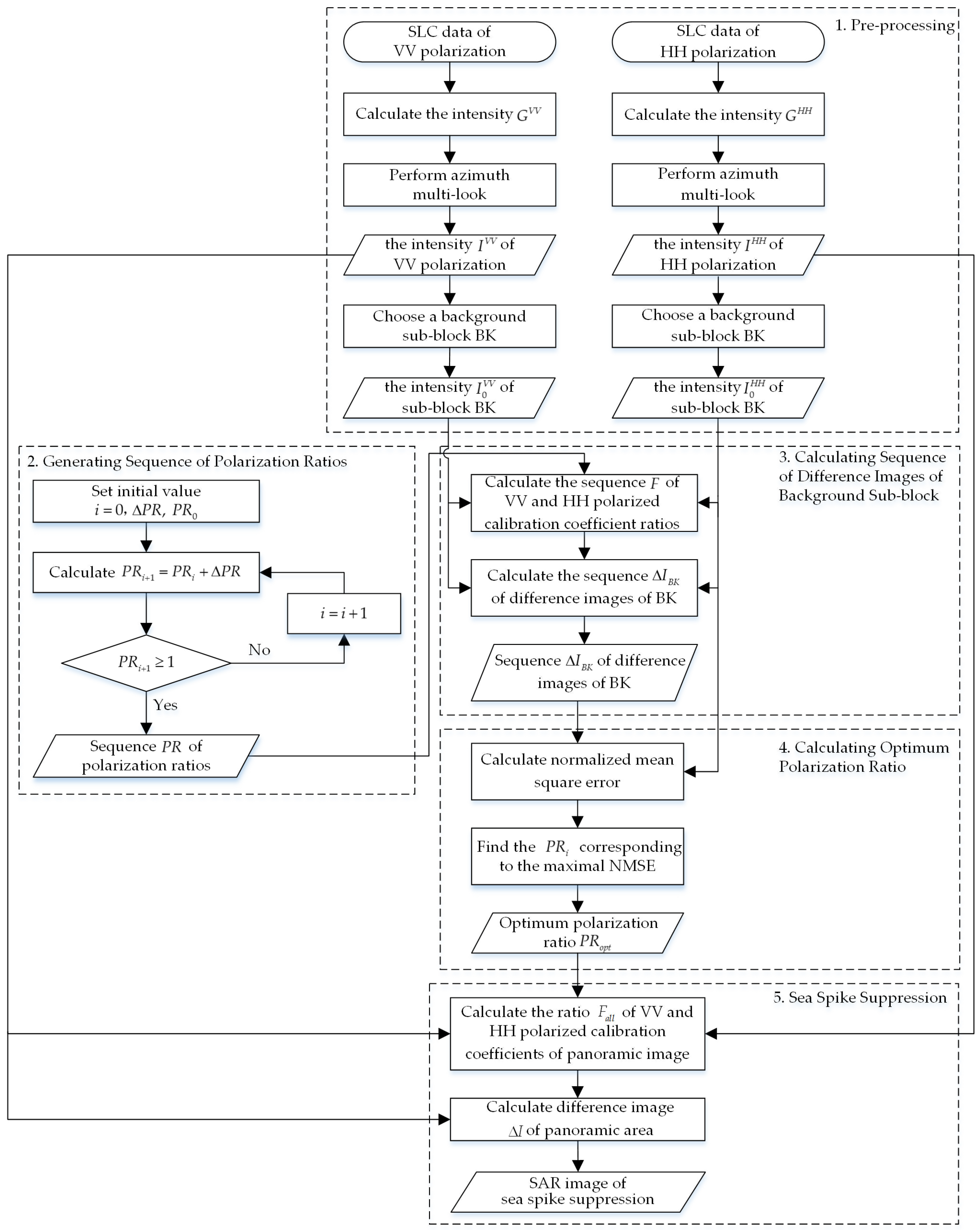
In this section, a sea spike suppression method based on optimum polarization ratio in airborne SAR images is proposed, which is designated for the single-look complex (SLC) data of dual-polarized airborne SAR. The flow chart of the proposed method is shown in
Figure 1. As can be seen, the method can be divided into five parts: pre-processing, generating sequence of polarization ratios, calculating sequence of difference images of background sub-block, calculating optimum polarization ratio and sea spike suppression. The five parts are introduced below.
2.1. Pre-Processing
The intensities of the VV and HH polarized SLC data are calculated and denoted as
and
, respectively. These SLC images are dealt through the azimuth multi-look processing, thus the influence of speckle noises can be reduced. The number
of looks is determined by the ratio of the range resolution and the azimuth resolution, which can be expressed as
where
denotes the function of round-down,
indicates the size of the range resolution cell of the SLC images, and
indicates the size of the azimuth resolution cell. After the azimuth multi-look processing, the intensities of VV and HH polarization are
and
, respectively.
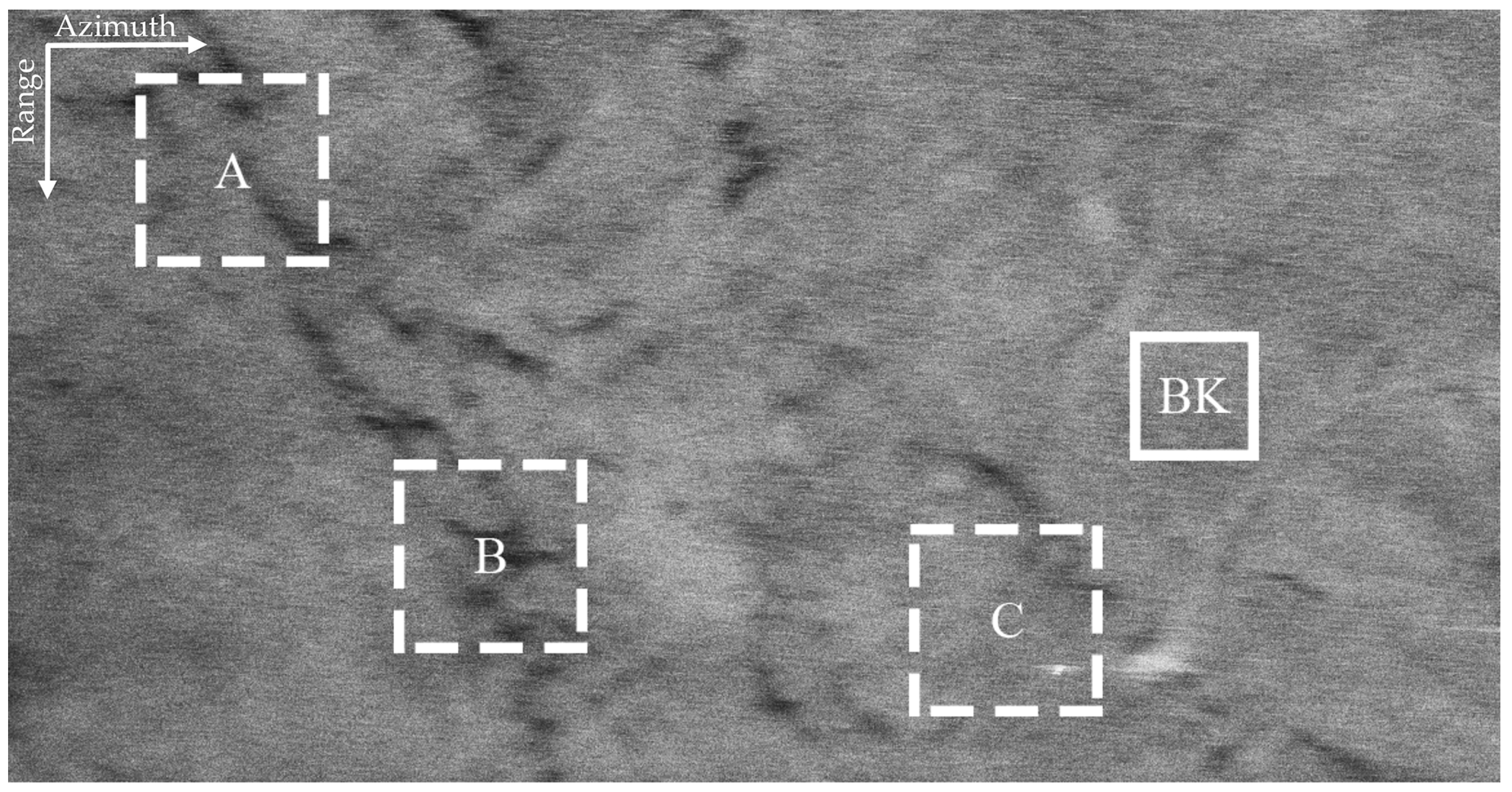
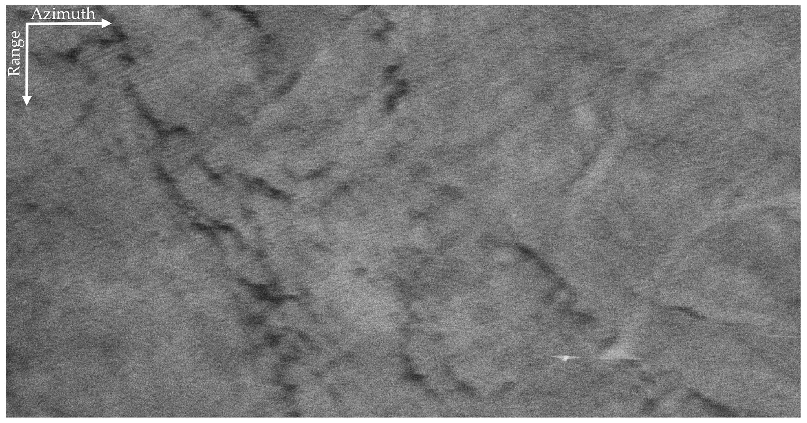
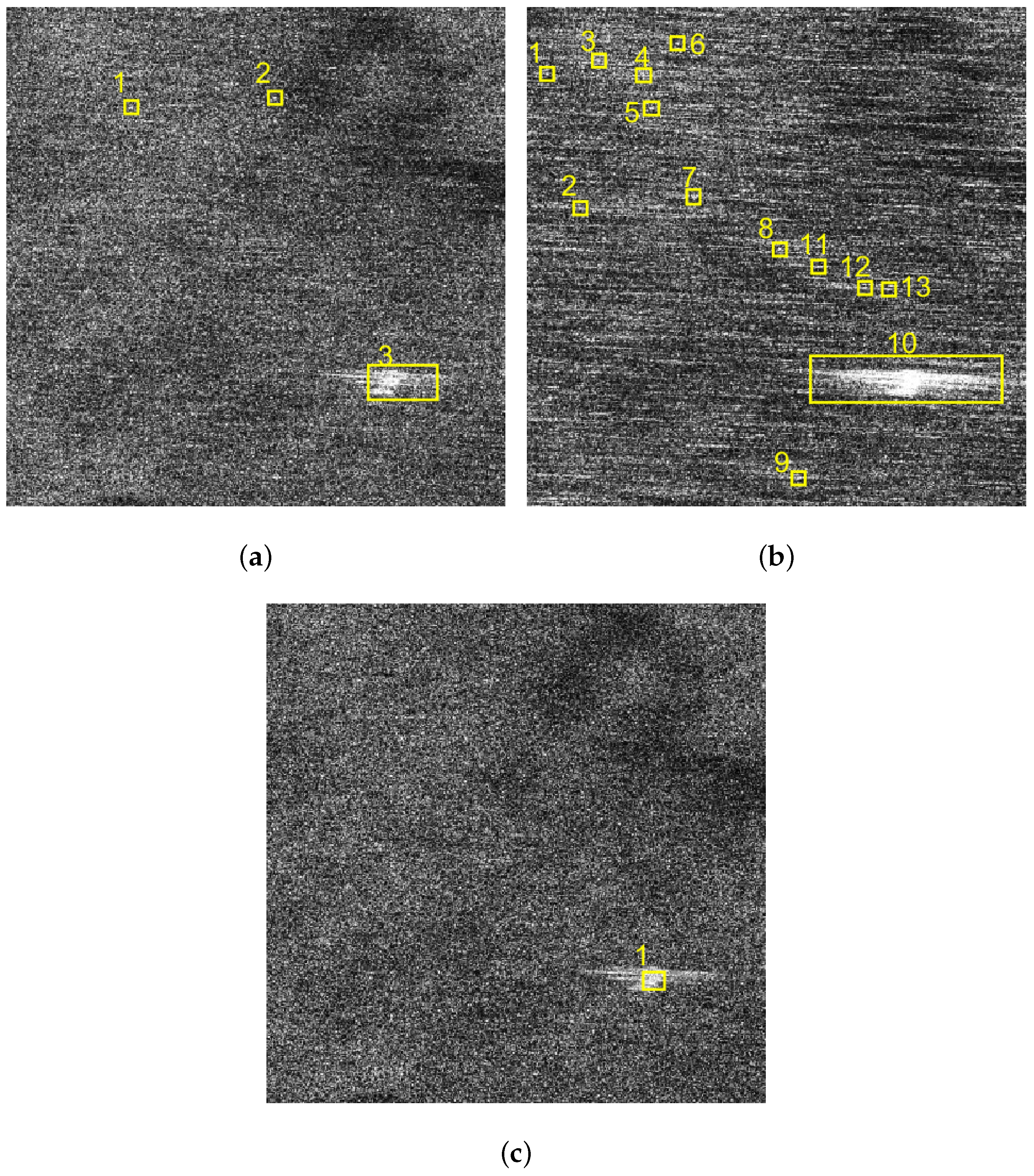
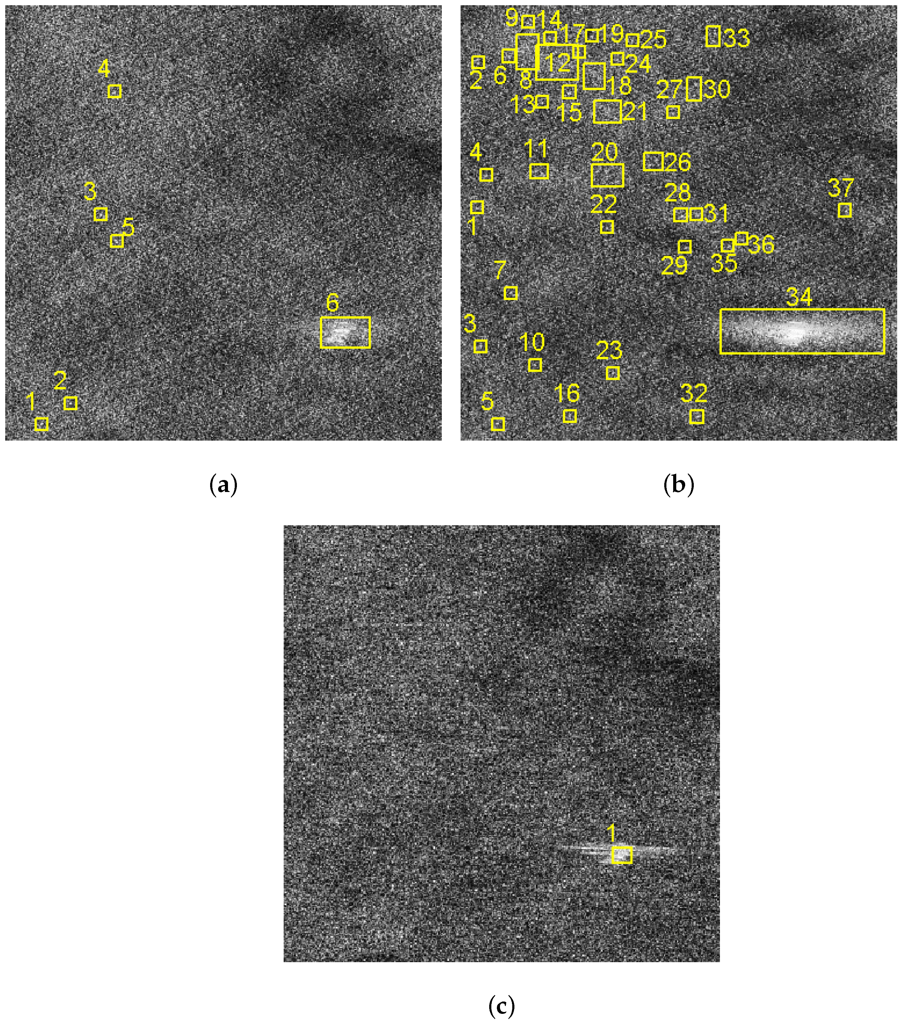
From and , we select a background sub-block, i.e., BK, according to the following two constraints: (1) sea spikes must exist in BK; and (2) no artificial targets exist in BK. SAR ocean images generally contain man-made targets such as ships and oil spills, which will influence the subsequent processing. For this reason, a uniform background sub-block containing only sea spikes is selected for subsequent calculating the sequence of difference images of background sub-block and optimum polarization ratio.
2.2. Generating Sequence of Polarization Ratios
The polarization ratio of the background sub-block BK is defined as the ratio of HH polarized backscatter coefficient
to VV polarized backscatter coefficient
, i.e.,
The fundamental relationship between the backscattering coefficient of background sub-block and SAR image intensity is defined as the equation [
15]
where
is the polarization mode, and
is the calibration coefficient for the
polarized background sub-block BK. According to the literature [
16], the calibration coefficient is a function of slant range. Since the slant range within the background sub-block BK slowly changes, the calibration coefficient here can be approximated as a constant
.
Thus, substituting Equation (
3) into Equation (
2), it can be get that
is defined as the ratio of the calibration coefficient of VV polarization to that of the HH polarization in the background sub-block BK
Hence, Equation (
4) can be simplified to
Breaking waves have been suggested as the main contributor to sea spikes [
5,
6,
7]. In the case of high frequency (X, Ku, Ka band), SAR ocean surface imaging needs to consider the impact of breaking waves on the polarization ratio. Therefore, this paper chooses the theoretical model of the polarization ratio to analyze, which considers the impact of breaking waves [
17]. The ratio of VV polarized backscatter coefficient to HH polarized backscatter coefficient is expressed as
where
where
is the ratio of VV polarized backscatter coefficient to HH polarized backscatter coefficient for the two-scale Bragg scattering. The Bragg wavelength depends on the local incidence angle:
, where
is the radar wavelength [
18].
is the incidence angle and
is the tuning parameter.
Therefore, the ratio of HH polarized backscatter coefficient to VV polarized backscatter coefficient can be expressed as
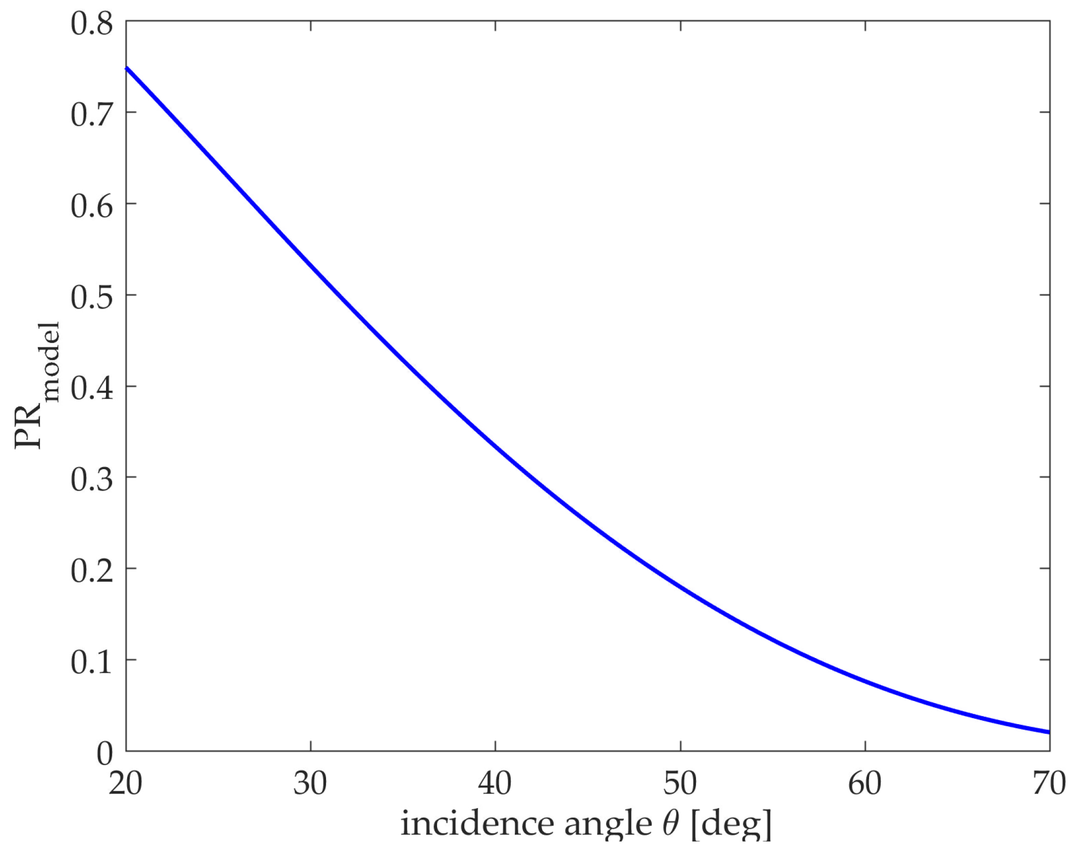
In the literature [
17], the X-band SAR data is fitted to obtain
, which is under the conditions of medium wind speed and cross wind direction. At present, the curve of polarization ratio
variation in the model with the incidence angle
is shown in
Figure 2.
Airborne SAR generally works at medium incidence angle. According to Equation (
9), when the medium incidence angle changes a little, the polarization ratio is almost unchanged with different values of
. For example, when
, if the incidence angle is shifted
around
, the value of the polarization ratio is approximately shifted
. Therefore, it can be assumed that the polarization ratio in the background sub-block BK is a constant. Combined with Equation (
6), the polarization ratio
of the background sub-block BK is expressed as
where
represents the averaging function.
can be written as
where
is the coordinates of a pixel, satisfying
and
.
In practice, atmospheric turbulences can produce large motion errors in airborne SAR systems, which introduce radiometric distortions in the SAR data [
19]. Besides, it is quite difficult to derive absolutely calibrated backscattering coefficient of ocean due to the system noise [
20]. Therefore, airborne SAR data is usually uncalibrated when observing the ocean. In this paper, we intend to generate a sequence of polarization ratios within the theoretical range to approach as close as possible to the polarization ratio
of the background sub-block in subsequent processing.
The redistribution of radar returns between short-scale Bragg waves and wave breaking is characterized by the value of
in the background sub-block BK [
21]. This ratio is minimal for the pure Bragg scattering and approaches 1 when breaking wave component dominates [
21]. Therefore, the polarization ratio
is in the range of
.
By traversing the theoretical interval
, the sequence of polarization ratios will be generated. For initialization, the iterating times
i is set as 0. For higher precision, the step-size
is defined between 0 and 0.1, and the initial value
of the polarization ratio is constrained in the range of 0.01–0.05. Thus, the traverse is conducted through
(where
) and the sequence
of polarization ratios is obtained as
2.4. Calculating Optimum Polarization Ratio
In this paper, we define the polarization ratio that is the closest to the
as the optimum polarization ratio
. When
,
and the difference image
of background sub-block BK correspondingly can be acquired by Equation (
18).
Combining Equations (
14) and (
20), it can be found that
is proportional to
at this time. This means when
, the difference image is regarded as the result of sea spike suppression. Thus, the optimum polarization ratio
will be obtained by comparing the sequence
of difference images of the background sub-block BK.
Since the effect of sea spikes on HH polarization is greater than those on the VV polarization [
23], the normalized mean square error (NMSE) between the HH polarization intensity
and the sequence
of difference images will be used as the evaluation index to obtain the optimum polarization ratio
. The
corresponding to each difference image
is calculated as
Consequently, these NMSEs are compared one by one. The maximal
reflects the dissimilarity between the corresponding difference image
and the HH polarized intensity
reaches largest, and the effect of sea spike suppression is optimum. Thus the optimum polarization ratio
is found.


