Smart Cutting Tools Used in the Processing of Aluminum Alloys
Abstract
:1. Introduction
2. Materials and Methods
2.1. Materials Used in Research
2.2. Equipment and Tools Used in the Processing by Cutting
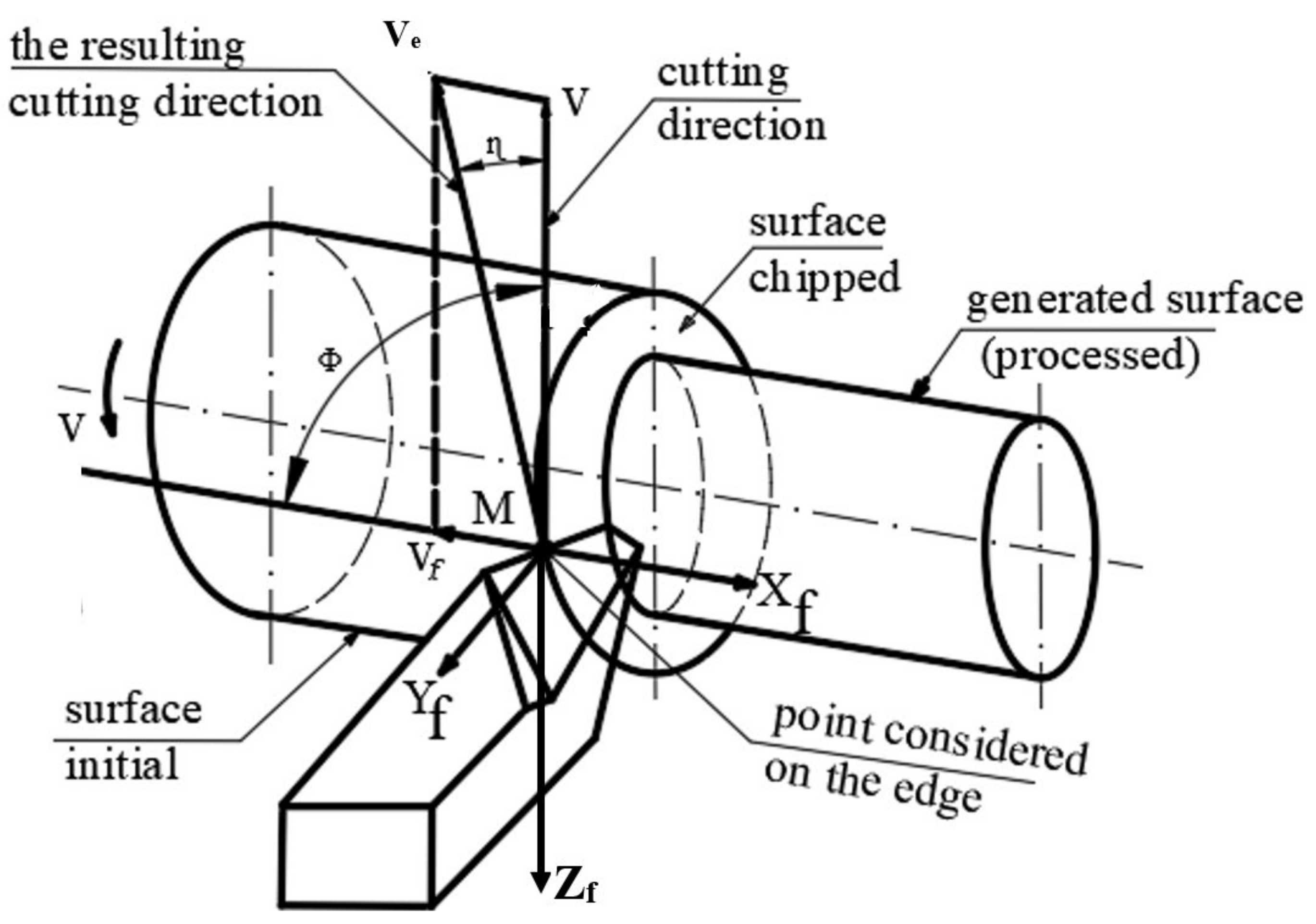
2.3. Analysis of the Evolution of the Functional Geometry of the Tool When Turning with Longitudinal Advance
2.4. Measurement of Vibrations That Occur during the Cutting Process
- −
- Taylor’s hypothesis—the variation of the cutting forces, during the chip formation process, can determine the appearance of autovibrations;
- −
- Kashirin’s theory—the adoption of an inappropriate geometry for the tool release face can cause the appearance of high frictional forces on the tool release face, which has effects on the autovibration phenomenon;
- −
- Sokolcvsky’s theory—autovibrations are introduced by a variation of the geometry of the cutting tool during surface processing;
- −
- Harnis and Grig’s theory—the continuous variation of the cutting depth can determine different values of the total force that appear in the cutting process, and this can determine the occurrence of autovibrations.
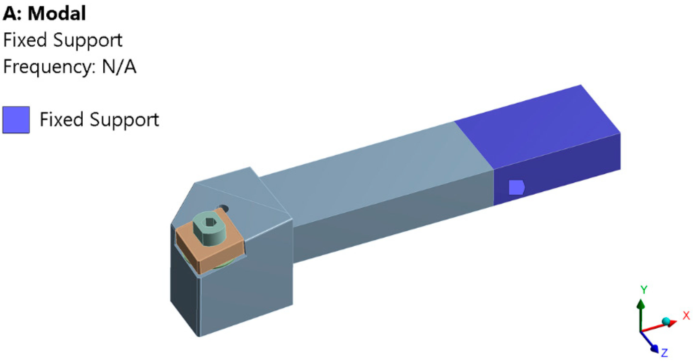
2.5. Analysis of the Own Modes of Vibrations Using FEM
- −
- determination of the response to free vibrations [f = 0]—modal analysis;
- −
- determination of the excitation response with periodic forces [f(t)—Periodic]—harmonic analysis;
- −
- determination of the excitation response in transient regime [f(t)—Transient]—analysis in transient regime.
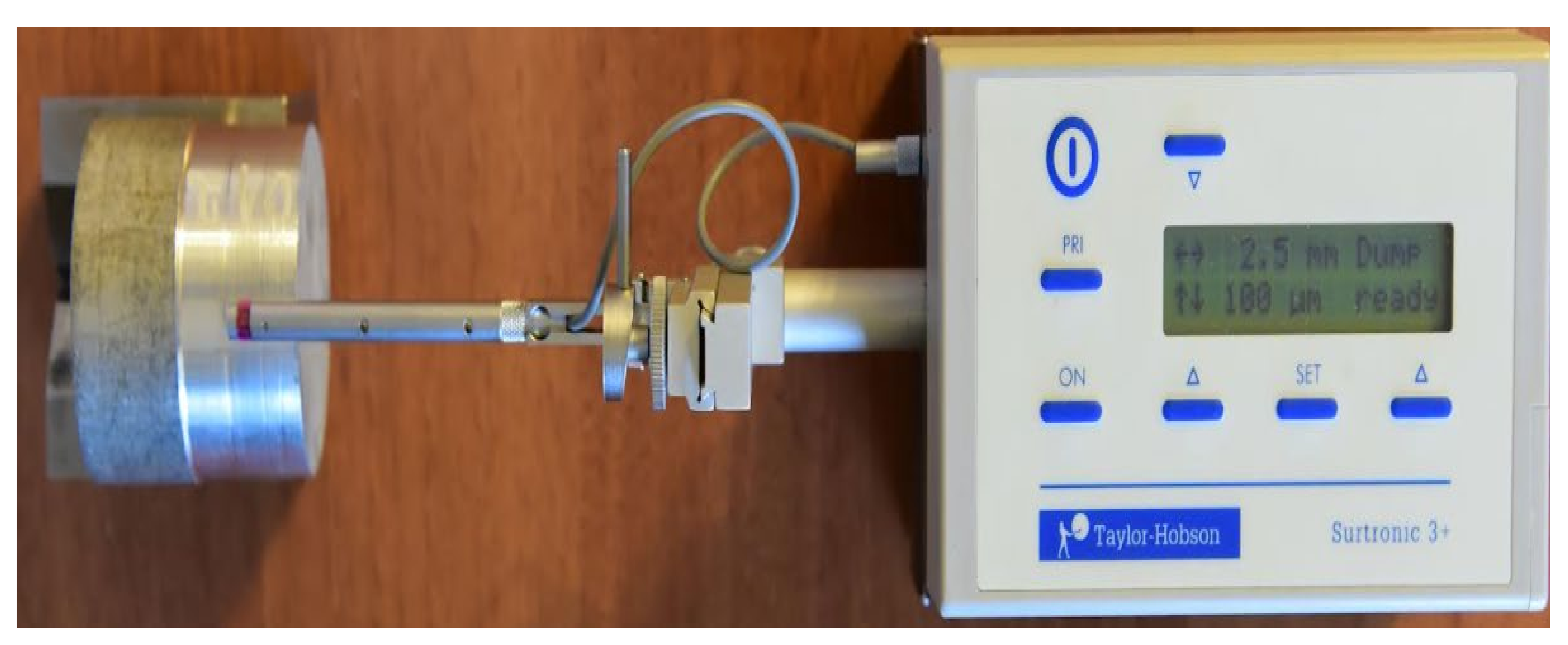
2.6. Measurement of the Roughness of the Processed Surfaces
3. Results and Discussion
3.1. Analysis of Vibrations That Occur during the Cutting Process
- −
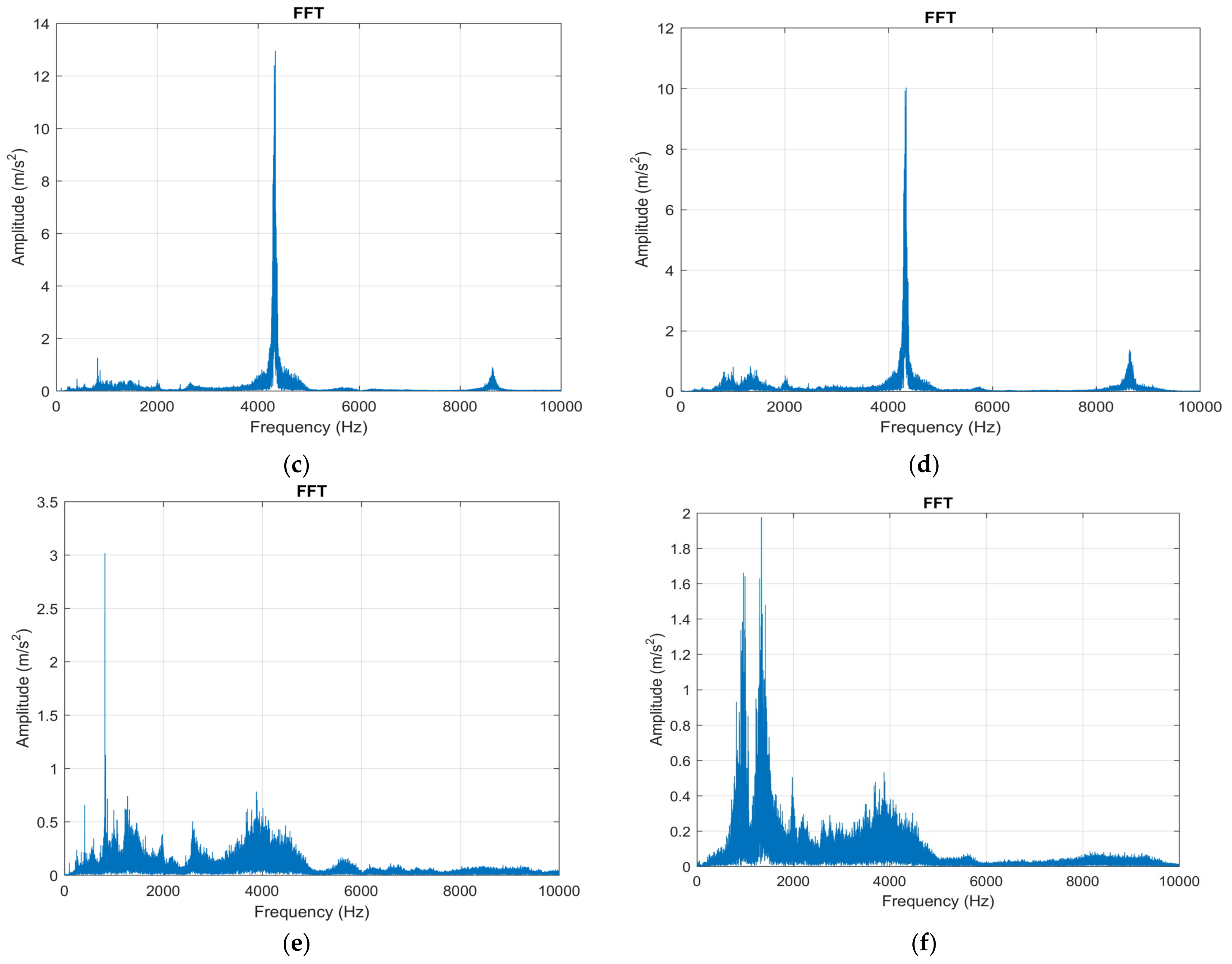
- in the Z direction in the case of using the cutting tool T01 amplitude of vibrations has a maximum value of approximately 2.7 m/s2, and in the case of using the cutting tool T02 the amplitude of vibrations has a maximum value of approximately 1 m/s2. Thus, it was observed that when using the T02 cutting tool, a considerable decrease in vibration amplitude was obtained by 2.7 times. This demonstrates that the use of smart tools T02 allows a considerable decrease in the amplitude of vibrations which can be explained by the possibility of ensuring an optimal functional geometry for the cutting tool and the considerable reduction of frictional forces. After testing the T02 tool, the T03 tool was used in the research, which involved placing two spring washers under the removable plate. The FFT analysis performed when using this tool showed that the maximum amplitude of vibrations was 3 m/s2. Thus, the amplitude of vibrations when using this cutting tool is about 10% higher than when the cutting tool T01 was used and three times larger than when the cutting tool T02 was used. This demonstrates that, although in the case of the T03 tool an attempt was made to create a smart tool that would allow the adjustment of the functional geometry of the tool in a larger area, the rigidity of the cutting tool was greatly reduced. Under these conditions, in the case of tool T03, although a substantial reduction of the frictional forces can be obtained on the clearing and laying faces of the tool, nevertheless, this reduction of the frictional forces does not compensate for the decrease of the rigidity of the cutting tool. As a result, a correlation is required between the parameters of the spring system arranged under the removable plate, the cutting forces, the friction forces, and the rigidity of the cutting tool;
- −
- the analysis of the amplitude of vibrations on the X direction in the case of using the cutting tool T01 showed a value of 1.4 m/s2. This lower value of the X-direction vibration amplitude compared to the Z-direction vibration amplitude is explained by the fact that the X-direction cutting forces are about half the Z-direction cutting forces. When using smart tool T02 in the X direction it was found that the amplitude of vibrations was about 0.03 m/s2. This demonstrates a considerable reduction in vibration amplitude and in the X direction when using the T02 smart tool. The amplitude of vibrations in the case of using the smart tool T03 was about 1.7 m/s2 which shows that even in the X direction the use of a tool that does not have a proper rigidity can cause an amplification of the vibration phenomenon with negative effects on the conditions in which the machining process is carried out.
- −
- the analysis of the Z-direction spectrograms showed that, when using the T01 tool, a maximum amplitude of vibrations is obtained at the beginning of the machining process, and this can be explained by the phenomena accompanying the cutting process at the tool entry into the cut. Additionally, the maximum value of the vibration amplitude was 6 m/s2. It should be noted that when using the smart tool T02 the vibration amplitude in the range up to 5000 Hz is approximately zero or very small. Thus, considering the analyzed frequency range, 10–10,000 Hz, it can be said that the use of the smart tool T02 determines the almost entire elimination of vibrations. If the T03 smart tool was used, the vibration amplitude has approximately the same values as in the case of the T01 tool, with a substantial increase in the vibration amplitude at very high frequencies. This demonstrates that the use of two spring washers is not indicated as it causes a decrease in the stiffness of the active part of the cutting tool, and this can increase the amplitude of the vibrations;
- −
- although the magnitude of the cutting force acting in the X direction is much smaller than that acting in the Z direction, a STFT analysis was also performed and, in this case, the specific spectrograms were drawn, Figure 8b,d,f. The analysis of the spectrograms showed that the maximum values of the vibration amplitude are higher in the X direction than in the Z direction. This is explained by the fact that, although the cutting force is lower in the X direction compared to the one in the Z direction, however, the frictional force that causes the vibrations to occur is much higher on the face of the tool in the X direction. Thus, the use of the smart tool can allow to obtain an optimal functional geometry of the tool, especially in terms of the functional seating angle of the αFe tool. If the tool was used in machining in the classic construction version T01, a maximum value of the vibration amplitude of approximately 6.9 m/s2 was obtained. The use of the first type of T02 smart tool allowed a decrease in amplitude in the range of interest 10–10,000 Hz to a value of about 0.8 m/s2. Thus, it was demonstrated that the use of the T02 tool allows a considerable reduction in vibration amplitude by about 8 times. However, the use of the T02 tool is not recommended for the frequency value range between 5800 and 6000 Hz, when the amplitude of vibrations increases greatly up to 48 m/s2. The use of the T03 smart tool did not allow to obtain the best results in terms of vibration amplitude because vibrations have maximum values in the range of interest 10–10,000 Hz after which the vibration amplitude decreases showing an increase in amplitude value at a frequency value of 5000 Hz. This behavior of the T03 tool demonstrates that a smart tool must be constructively optimized given the design of a spring system arranged under the removable plate adapted to the conditions in which the cutting process takes place. It can also be concluded that the smart tool T02 has the best behavior in terms of vibration in the processing conditions of aluminum alloy A2024-T351.
3.2. Results Obtained in the Analysis of the Own Modes of Vibrations Using FEM
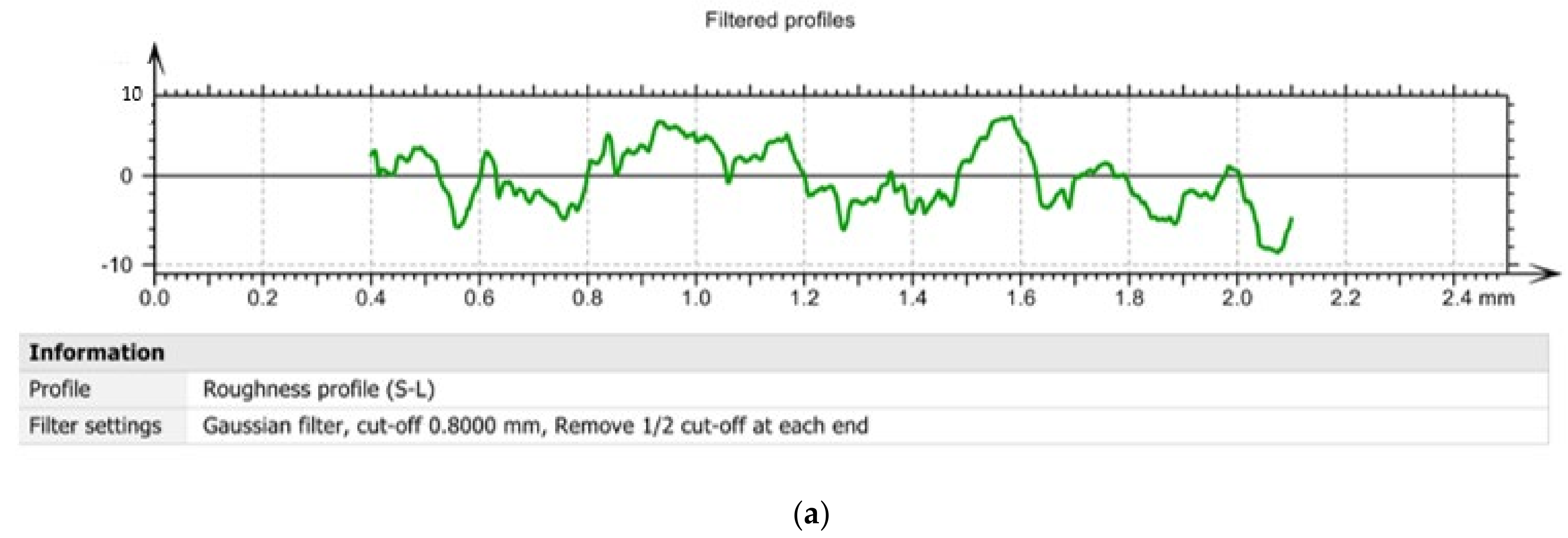
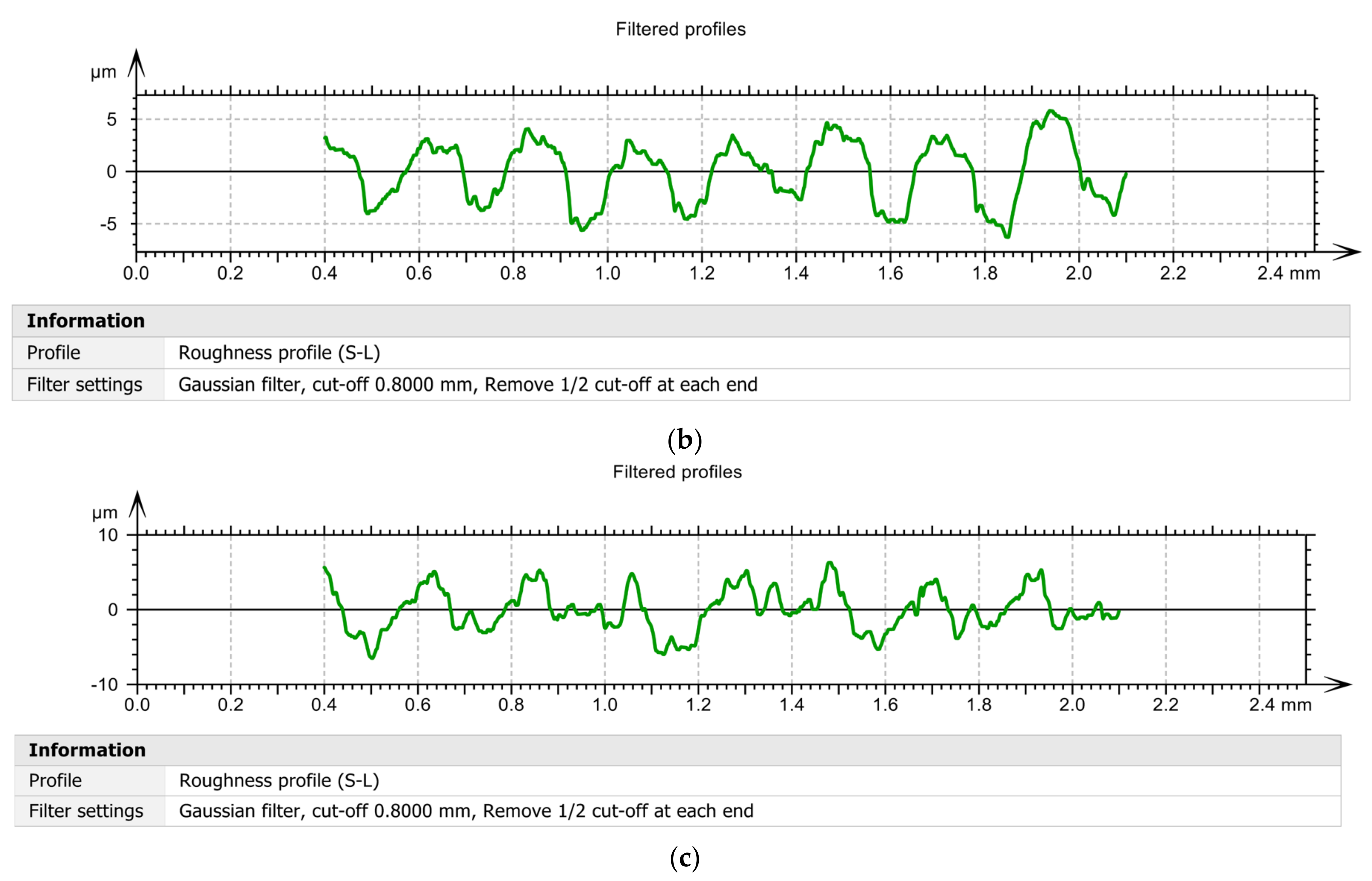
3.3. The Influence of the Use of Smart Tools on the Roughness of Surfaces Machined through Cutting
4. Conclusions
- ▪
- the use of the smart tool T02 determines the almost entire elimination of vibrations, and if a smart tool T03 with a non-optimized elastic system was used, a substantial reduction of the vibration amplitude was not achieved, having approximately the same values as in the case of the tool made in classic constructive variant;
- ▪
- the use of a system consisting of two spring washers is not indicated as it causes a decrease in the stiffness of the active part of the cutting tool, and this may increase the amplitude of the vibrations;
- ▪
- vibration analysis by the FFT and STFT method, respectively, allowed an in-depth analysis of the vibration amplitude for a frequency of up to 10,000 Hz;
- ▪
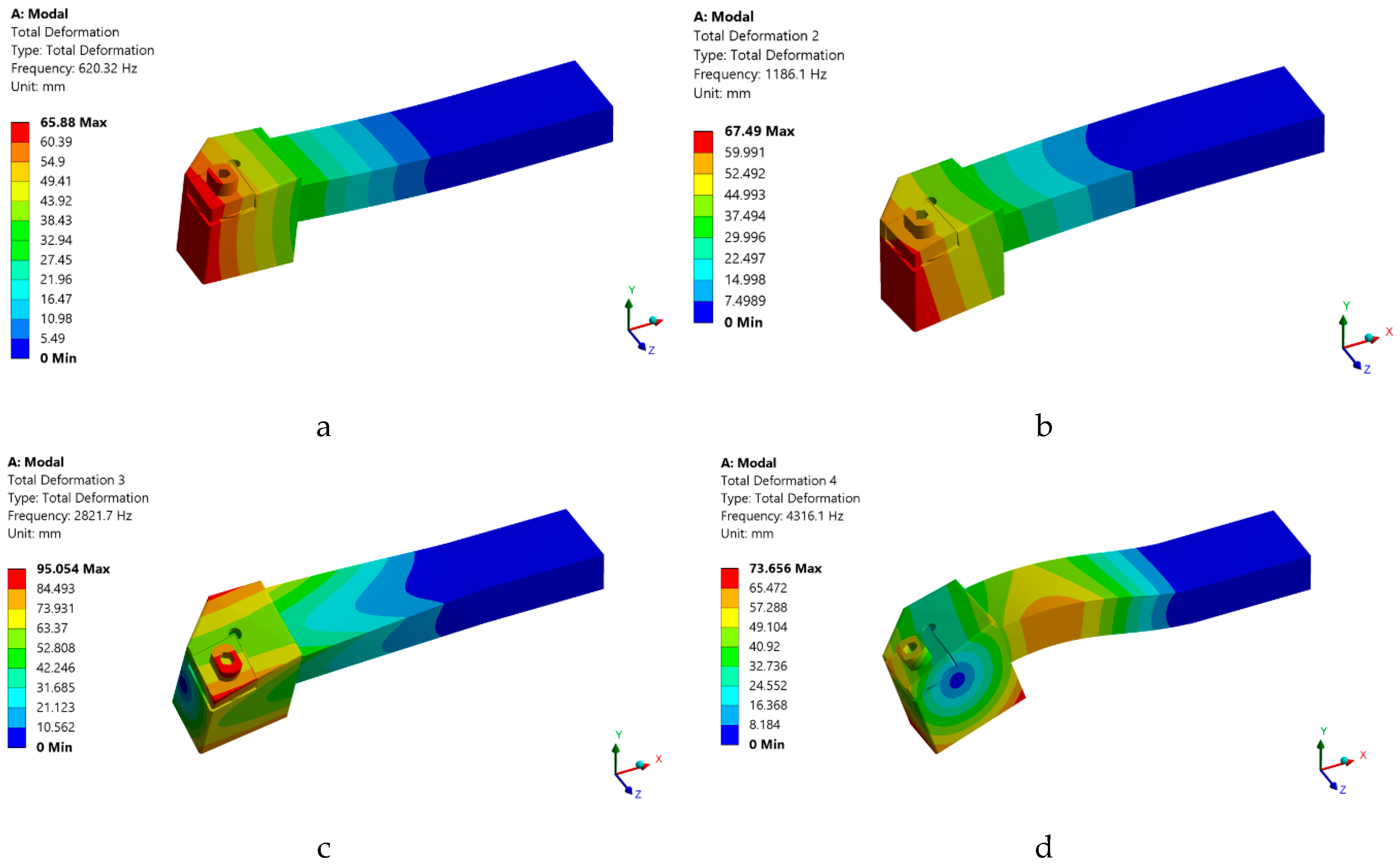
- FEM modeling of the own numerical vibration mode of the tools used in the machining, demonstrated that the use of smart tools allows to greatly increase the speed of the part at which the first proper vibration mode appears. Thus, this type of smart tool can be used successfully even when the speed is very high without the danger of the occurrence of the resonance phenomenon. Additionally, from the analysis of the results obtained in the case of FEM application, it was observed that the first own vibration mode (620.3 Hz), corresponds to a speed of 37,219 rpm, well above the working speed of 800 rpm;
- ▪
- the use of smart tools allows to obtain very low roughness values compared to the roughness values obtained compared to the roughness obtained when using tools in the classic construction version;
- ▪
- the results obtained in terms of surface roughness were very promising, but there may still be a number of aspects that can be optimized, such as, for example, those related to the characteristics of the damping system arranged under the removable plate;
- ▪
- the research results, using the proposed tool, showed that it can be considered a smart tool that allows an instantaneous continuous adjustment of the parameters of the turning process, without the need for certain response times, as in the case of other types of smart tools.
Author Contributions
Funding
Institutional Review Board Statement
Informed Consent Statement
Data Availability Statement
Conflicts of Interest
References
- Rizzo, A.; Goel, S.; Luisa Grilli, M.; Iglesias, R.; Jaworska, L.; Lapkovskis, V.; Novak, P.; Postolnyi, B.O.; Valerini, D. The Critical Raw Materials in Cutting Tools for Machining Applications: A Review. Materials 2020, 13, 1377. [Google Scholar] [CrossRef] [PubMed] [Green Version]
- Grilli, M.; Bellezze, T.; Gamsjäger, E.; Rinaldi, A.; Novak, P.; Balos, S.; Piticescu, R.; Ruello, M. Solutions for Critical Raw Materials under Extreme Conditions: A Review. Materials 2017, 10, 285. [Google Scholar] [CrossRef] [Green Version]
- Dobrota, D.; Titu, M.A.; Dobrita, F.; Petrescu, V. The analysis of homogeneity of the chemical composition in castings made of aluminum alloy. Rev. Chim. 2016, 67, 520–523. [Google Scholar]
- Zu, W.; Jianxin, D.; Yang, C.; Youqiang, X.; Jun, Z. Performance of the self-lubricating textured tools in dry cutting of Ti-6Al-4V. Int. J. Adv. Manuf. Technol. 2012, 62, 943–951. [Google Scholar]
- Teti, R.; Micheletti, G. Tool wear monitoring through acoustic emission. CIRP Ann. 1989, 38, 99–102. [Google Scholar] [CrossRef]
- Xing, Y.; Deng, J.; Li, S.; Yue, H.; Meng, R.; Gao, P. Cutting performance and wear characteristics of Al2O3/TiC ceramic cutting tools with WS2/Zr soft-coatings and nano-textures in dry cutting. Wear 2014, 318, 12–26. [Google Scholar] [CrossRef]
- Fallqvist, M.; Schultheiss, F.R.; Saoubi, M.; Olsson, M.; Ståhl, J.E. Influence of the tool surface micro topography on the tribological characteristics in metal cutting: Part I Experimental observations of contact conditions. Wear 2013, 298–299, 87–98. [Google Scholar] [CrossRef]
- Brili, N.; Ficko, M.; Klančnik, S. Tool Condition Monitoring of the Cutting Capability of a Turning Tool Based on Thermography. Sensors 2021, 21, 6687. [Google Scholar] [CrossRef] [PubMed]
- Giasin, K.; Hodzic, A.; Phadnis, V.; Ayvar-Soberanis, S. Assessment of cutting forces and hole quality in drilling Al2024 aluminium alloy: Experimental and finite element study. Int. J. Adv. Manuf. Technol. 2016, 87, 2041–2061. [Google Scholar] [CrossRef]
- Köklü, U. Influence of the process parameters and the mechanical properties of aluminum alloys on the burr height and the surface roughness in dry drilling. Mater. Tehnol. 2012, 46, 103–108. [Google Scholar]
- Zhu, Z.; Guo, K.; Sun, J.; Li, J.; Liu, Y.; Zheng, Y.; Chen, L. Evaluation of novel tool geometries in dry drilling aluminium 2024-T351/titanium Ti6Al4V stack. J. Mater. Process. Technol. 2018, 259, 270–281. [Google Scholar] [CrossRef]
- Kuntoğlu, M.; Aslan, A.; Pimenov, D.Y.; Usca, Ü.A.; Salur, E.; Gupta, M.K.; Mikolajczyk, T.; Giasin, K.; Kapłonek, W.; Sharma, S. A Review of Indirect Tool Condition Monitoring Systems and Decision-Making Methods in Turning: Critical Analysis and Trends. Sensors 2021, 21, 108. [Google Scholar] [CrossRef]
- Makadia, A.J.; Nanavati, J. Optimisation of machining parameters for turning operations based on response surface methodology. Measurement 2013, 46, 1521–1529. [Google Scholar] [CrossRef]
- Mia, M.; Dhar, N.R. Prediction of surface roughness in hard turning under high pressure coolant using Artificial Neural Network. Measurement 2016, 92, 464–474. [Google Scholar] [CrossRef]
- Neşeli, S.; Yaldız, S.; Türkeş, E. Optimization of tool geometry parameters for turning operations based on the response surface methodology. Measurement 2011, 44, 580–587. [Google Scholar] [CrossRef]
- Kuntoğlu, M.; Aslan, A.; Sağlam, H.; Pimenov, D.Y.; Giasin, K.; Mikolajczyk, T. Optimization and Analysis of Surface Roughness, Flank Wear and 5 Different Sensorial Data via Tool Condition Monitoring System in Turning of AISI 5140. Sensors 2020, 20, 4377. [Google Scholar] [CrossRef]
- Lee, E.C.; Nian, C.Y.; Tarng, Y.S. Design of a dynamic vibration absorber against vibrations in turning operations. J. Mater. Process. Technol. 2001, 108, 278–285. [Google Scholar] [CrossRef]
- Sims, N.D. Vibration absorbers for chatter suppression: A new analytical tuning methodology. J. Sound Vib. 2007, 301, 592–607. [Google Scholar] [CrossRef] [Green Version]
- Moradi, H.; Bakhtiari-Nejad, F.; Movahhedy, M.R. Tunable vibration absorber design to suppress vibrations: An application in boring manufacturing process. J. Sound Vib. 2008, 318, 93–108. [Google Scholar] [CrossRef]
- Lee, J.; Berger, R.; Kim, J.H. Feasibility study of a tunable friction damper. J. Sound Vib. 2005, 283, 707–722. [Google Scholar] [CrossRef]
- Ferri, A.A. Friction damping and isolation systems. Trans. ASME 1995, 117, 196–206. [Google Scholar] [CrossRef]
- Demyanov, V.F.; Malozemov, V.N. Introduction to Minimax; Dover Publications Inc.: Mineola, NY, USA, 2014. [Google Scholar]
- Wang, M.; Zan, T.; Yang, Y.; Fei, R. Design and implementation of nonlinear TMD for chatter suppression: An application in turning processes. Int. J. Mach. Tools Manuf. 2010, 50, 474–479. [Google Scholar] [CrossRef]
- Thomazella, R.; Lopes, W.N.; Aguiar, P.R.; Alexandre, F.A.; Fiocchi, A.A.; Bianchi, E.C. Digital signal processing for self-vibration monitoring in grinding: A new approach based on the time-frequency analysis of vibration signals. Measurement 2019, 145, 71–83. [Google Scholar] [CrossRef]
- Fu, Y.; Zhang, Y.; Gao, H.; Mao, T.; Zhou, H.; Sun, R.; Li, D. Automatic feature constructing from vibration signals for machining state monitoring. J. Intell. Manuf. 2019, 30, 995–1008. [Google Scholar] [CrossRef]
- Bhowmik, B.; Tripura, T.; Hazra, B.; Pakrashi, V. First-order eigen-perturbation techniques for real-time damage detection of vibrating systems: Theory and applications. Appl. Mech. Rev. 2019, 71, 060801. [Google Scholar] [CrossRef]
- Choi, J.P.; Lee, S.J.; Kwon, H.D. Roundness Error Prediction with a Volumetric Error Model Including Spindle Error Motions of a Machine Tool. Int. J. Adv. Manuf. Technol. 2003, 21, 923–928. [Google Scholar] [CrossRef]
- Manhertza, G.; Akos Bereczkyb, A. STFT spectrogram based hybrid evaluation method for rotating machine transient vibration analysis. Mech. Syst. Signal Process. 2021, 154, 107583. [Google Scholar] [CrossRef]
- Rankine, L.; Mesbah, M.; Boashash, B. IF estimation for multicomponent signals using image processing techniques in the time-frequency domain. Signal Process. 2007, 87, 1234–1250. [Google Scholar] [CrossRef] [Green Version]
- Zagórski, I.; Kulisz, M.; Kłonica, M.; Matuszak, J. Trochoidal milling and neural networks simulation of magnesium alloys. Materials 2019, 12, 2070. [Google Scholar] [CrossRef] [Green Version]
- Abdoush, Y.; Pojani, G.; Corazza, G. Adaptive Instantaneous Frequency Estimation of Multicomponent Signals Based on Linear Time–Frequency Transforms, Computer Science. IEEE Trans. Signal Process. 2019, 67, 3100–3112. [Google Scholar] [CrossRef]
- Wang, Y.; Tse, P.W.; Tang, B.; Qin, Y.; Deng, L.; Huang, T.; Xu, G. Order spectrogram visualization for rolling bearing fault detection under speed variation conditions. Mech. Syst. Signal Process. 2019, 122, 580–596. [Google Scholar] [CrossRef]
- Espinoza-Sepulveda, N.; Sinha, J. Mathematical Validation of Experimentally Optimised Parameters Used in a Vibration-Based Machine-Learning Model for Fault Diagnosis in Rotating Machines. Machines 2021, 9, 155. [Google Scholar] [CrossRef]
- Segreto, T.; Caggiano, A.; Karam, S.; Teti, R. Vibration Sensor Monitoring of Nickel-Titanium Alloy Turning for Machinability Evaluation. Sensors 2017, 17, 2885. [Google Scholar] [CrossRef] [Green Version]
- Niancong, L.; Baolin, L.; Hao, J.; Shenghong, W.; Chengwen, Y.; Yun, C. Study on vibration and surface roughness in MQCL turning of stainless steel. J. Manuf. Process. 2021, 65, 343–353. [Google Scholar] [CrossRef]
- Skrzyniarz, M.; Nowakowski, L.; Miko, E.; Borkowski, K. Influence of Relative Displacement on Surface Roughness in Longitudinal Turning of X37CrMoV5-1 Steel. Materials 2021, 14, 1317. [Google Scholar] [CrossRef]
- Abdullah, A. Optimization and analysis of process parameters for flank wear, cutting forces and vibration in turning of AISI 5140: A comprehensive study. Measurement 2020, 163, 107959. [Google Scholar]
- Yemul, N.N.; Deshpande, G.R. Literature Review on Tool Wear in Turning Operation of Aluminium. Int. J. Innov. Eng. Res. Technol. 2021, 8, 15–17. [Google Scholar]
- Pankaj, K.S. Optimization of Machining Parameters for Turning of Aluminium Alloy-2011 using Taguchi Method. IOP Conf. Ser. Mater. Sci. Eng. 2021, 1116, 012092. [Google Scholar]
- Dutta, S.; Kumar, S.; Narala, R. Optimizing turning parameters in the machining of AM alloy using Taguchi methodology. Measurement 2021, 169, 108340. [Google Scholar] [CrossRef]
- Huang, J.; Pham, D.T.; Ji, C.; Zhou, Z. Smart Cutting Tool Integrated with Optical Fiber Sensors for Cutting Force Measurement in Turning. IEEE Trans. Instrum. Meas. 2020, 69, 1720–1727. [Google Scholar] [CrossRef]
- Gürgen, S.; Kuşhan, M.C. The effect of silicon carbide additives on the stab resistance of shear thickening fluid treated fabrics. Mech. Adv. Mater. Struct 2017, 24, 1381–1390. [Google Scholar]
- Wu, X.; Zhong, F.; Yin, Q.; Huang, C. Dynamic response of shear thickening fluid under laser induced shock. Appl. Phys. Lett. 2015, 106, 71903. [Google Scholar] [CrossRef] [Green Version]












| Al | Cr | Cu | Fe | Mg | Mn | Si | Ti | Zn |
|---|---|---|---|---|---|---|---|---|
| 90.7–94.7 | max. 0.1 | 3.8–4.9 | max. 0.5 | 1.2–1.8 | 0.3–0.9 | max. 0.5 | max. 0.1 | max. 0.25 |
| Properties | Value | Comments |
|---|---|---|
| Hardness, Brinell | 120 | AA; Typical; 500 g load; 10 mm ball |
| Ultimate Tensile Strength | 469 MPa | AA; Typical |
| Tensile Yield Strength | 324 MPa | AA; Typical |
| Elongation at Break | 19% | AA; Typical; 1/2 in. (12.7 mm) Diameter |
| Modulus of Elasticity | 73.1 GPa | AA; Typical; Average of tension and compression. Compression modulus is about 2% greater than tensile modulus. |
| Ultimate Bearing Strength | 814 MPa | Edge distance/pin diameter = 2.0 |
| Bearing Yield Strength | 441 MPa | Edge distance/pin diameter = 2.0 |
| Poisson’s Ratio | 0.33 | |
| Fatigue Strength | 138 MPa | AA; 500,000,000 cycles completely reversed stress; RR Moore machine/specimen |
| Shear Modulus | 28 GPa | |
| Shear Strength | 283 MPa | AA; Typical |
| The Sample Number | In Case of Machining Performed with Tool T01 | In Case of Machining Performed with Tool T02 | In Case of Machining Performed with Tool T03 |
|---|---|---|---|
| 1 | 2.717397 | 1.448305 | 2.506057 |
| 2 | 2.172855 | 1.468041 | 2.471939 |
| 3 | 2.477422 | 1.526573 | 2.389087 |
| 4 | 2.646282 | 1.581081 | 2.262302 |
| 5 | 2.464776 | 1.520499 | 2.162325 |
| 6 | 2.626595 | 1.598336 | 2.137241 |
| 7 | 2.237116 | 1.646847 | 2.388526 |
| 8 | 2.263172 | 1.688449 | 2.270452 |
| 9 | 2.173006 | 1.693019 | 2.347753 |
| 10 | 2.281989 | 1.700883 | 2.406131 |
| Mean | 2.406061 | 1.606203 | 2.232181 |
| St Dev | 0.206791 | 0.084961 | 0.120591 |
| Cvariation | 8.594601 | 2.259944 | 5.17075 |
| Median | 2.373382 | 1.598728 | 2.36814 |
| p-value | 0.197 | 0.94 | 0.504 |
Publisher’s Note: MDPI stays neutral with regard to jurisdictional claims in published maps and institutional affiliations. |
© 2021 by the authors. Licensee MDPI, Basel, Switzerland. This article is an open access article distributed under the terms and conditions of the Creative Commons Attribution (CC BY) license (https://creativecommons.org/licenses/by/4.0/).
Share and Cite
Dobrotă, D.; Racz, S.-G.; Oleksik, M.; Rotaru, I.; Tomescu, M.; Simion, C.M. Smart Cutting Tools Used in the Processing of Aluminum Alloys. Sensors 2022, 22, 28. https://doi.org/10.3390/s22010028
Dobrotă D, Racz S-G, Oleksik M, Rotaru I, Tomescu M, Simion CM. Smart Cutting Tools Used in the Processing of Aluminum Alloys. Sensors. 2022; 22(1):28. https://doi.org/10.3390/s22010028
Chicago/Turabian StyleDobrotă, Dan, Sever-Gabriel Racz, Mihaela Oleksik, Ionela Rotaru, Mădălin Tomescu, and Carmen Mihaela Simion. 2022. "Smart Cutting Tools Used in the Processing of Aluminum Alloys" Sensors 22, no. 1: 28. https://doi.org/10.3390/s22010028
APA StyleDobrotă, D., Racz, S.-G., Oleksik, M., Rotaru, I., Tomescu, M., & Simion, C. M. (2022). Smart Cutting Tools Used in the Processing of Aluminum Alloys. Sensors, 22(1), 28. https://doi.org/10.3390/s22010028


