Abstract
To investigate the influence of depth on the rockburst of surrounding rock in a circular tunnel, true-triaxial tests at different depths were carried out on cubic granite specimens with a circular through-going hole. A micro camera was used to monitor the rockburst process of the circular hole sidewall in real time. The test results show that the failure process at different depths can be divided into four periods: the calm period, the particle ejection period, the rock fragment exfoliation period, and the rock bursting period. With an increase in depth, the three-dimensional unequal stress state gradually increased; the failure range and the size of rock fragments increased, the initial failure vertical stress linearly increased, and the strength and stability of the surrounding rock were enhanced. Therefore, the support range of surrounding rock should be increased as the depth increased to improve the overall stability of surrounding rock and reduce the failure range.
1. Introduction
To meet the development and needs of the country, many underground projects have appeared, and the depth has gradually increased [1,2,3,4,5]. The depth has a significant impact on the mechanical properties of the rock. For example, Peng et al. [6,7] conducted uniaxial compression tests and dynamic impact tests on granite from various burial depths, and obtained that peak stress was fitted with a quadratic function in terms of the change in burial depth. Wang et al. [8] reported that the uniaxial compressive strength and the rockburst proneness increased by carrying out uniaxial compression tests on different buried deep limestones. After the underground engineering enters the deep, the deep rock mass is in a complex environment such as high geostress, high ground temperature, high karst water pressure and strong mining disturbance [9,10,11], which leads to a series of deep disasters, and rockburst is one of the common major disasters [12,13]. Rockburst is accompanied by the ejection of rock fragments and the release of a large amount of energy [14,15,16,17,18,19]. Strong rockburst often brings catastrophic consequences, causing casualties and damage to construction equipment, seriously hindering the smooth progress of production [20,21,22]. For example, on 31 May 2015, an extremely intense rockburst struck the headrace tunnel of the Neelum–Jhelum hydropower station in Pakistan, causing 3 deaths, 17 injuries, and serious damage to the TBM and surrounding rock mass. Consequently, more than half a year was needed for recovery before construction could continue [23,24]. On 28 November 2009, an extremely strong rockburst in a drainage tunnel at a depth of 2330 m caused seven deaths and one injury as well as the total destruction of the tunnel boring machine [25,26]. Since 2016, the mining depth of Yunnan Dahongshan Iron Mine has gradually entered the range of 767–1261 m, and the maximum development depth has reached 1301 m. During the construction process, several slight and moderate rockbursts occurred, and the number of rockbursts increased exponentially with the increase in burial depth [27]. Therefore, with the increase in depth, rockburst disaster becomes more prominent [28,29,30,31,32].
In view of the hazards of rockburst disasters, many scholars conducted a series of studies on the rockburst process and occurrence mechanism [33,34,35,36,37,38,39,40]. Singh [33,34] proposed that the use of burst proneness index to analyze rockburst was a simple and reliable method, and the physical and mechanical properties under uniaxial compression had an important influence on the burst proneness index. Si et al. [35,36] reported that the influence of bedding angle and loading rate on the rockburst process and characteristics under the uniaxial and triaxial compression. Wu et al. [37] obtained that the number of openings had a significant impact on the weakening effect of rock mechanical properties, and explained the crack initiation mechanism under the uniaxial compression. Hu et al. [38] observed the rockburst process of the surrounding rock in circular holes under two-dimensional stress conditions, and analyzed the spatial distribution and structural response characteristics of the rockburst process. Gong et al. [39,40] obtained that the effect of lateral stress on rockburst was more obvious than that of horizontal axial stress, and increasing the lateral stress can significantly reduce the severity of rockburst by conducting the true-triaxial tests on cube samples of 100 mm × 100 mm × 100 mm. However, there are relatively few studies on the influence of depth on the rockburst. As the depth increased, the elastic strain energy stored in the rock mass increased, and more elastic strain energy was released when rock failure occurred [41,42]. Therefore, it is necessary to carry out experimental studies on the effect of depth on rockburst process, characteristics and severity of the surrounding rock of the circular tunnel.
In this study, true-triaxial tests were conducted using a true-triaxial testing machine on 100 mm cubic granite specimens containing a circular through-going hole at different depths. The true-triaxial tests were carried out in strict accordance with the testing procedure in the ISRM Suggested Method (determining deformation and failure characteristics of rocks subjected to true triaxial compression) [43]. During the tests, the rockburst process of hole sidewall was monitored and recorded in real time by a micro camera. The influence of depth on rockburst characteristics and severity in circular hole was investigated. This study has important guiding significance for the prevention and control of surrounding rock in circular tunnel at different depths.
2. Experimental Procedures
2.1. Sample Preparation
The granite material was obtained from Changtai County, Zhangzhou City, Fujian Province, China. The naked-eye observation photo of granite material is shown in Figure 1a. A thin rock section was observed with a petrographic microscope under plane-polarized and cross-polarized lights, as shown in Figure 1b,c, and the mineral composition of the rock was approximately 49% quartz, 43% plagioclase, 4% biotite, 3% hornblende, and 1% opaque minerals. Based on IUGS classifications [44], the selected rock material belongs to the granodiorite.

Figure 1.
Granite material: (a) naked-eye observation, (b) plane-polarized light, and (c) cross-polarized light (the letters Q, Pl, Bt, and Hbl represent quartz, plagioclase, biotite, and hornblende, respectively).
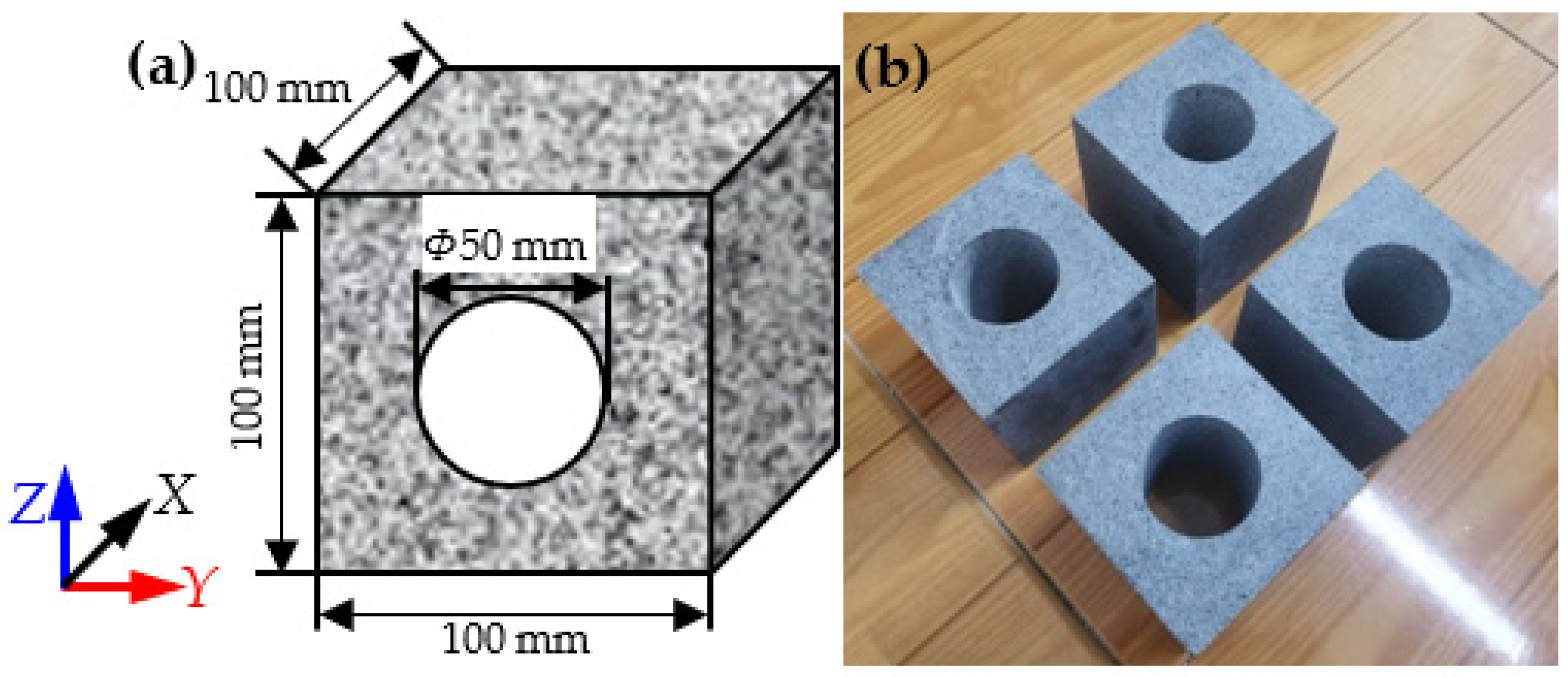
The granite material was cut into cubes with side lengths of 100 mm, and then a cylindrical through-going hole with a diameter of 50 mm was drilled in the center of the specimen, as shown in Figure 2. The machining precision strictly followed the ISRM standards for the cubic samples [43]. The P-wave velocity and density of the granite material were 4.9 km/s and 2766 kg/m3; the uniaxial compressive strength (UCS), elastic modulus, and Poisson’s ratio of granite material were 261.6 MPa, 57.9 GPa, and 0.21, respectively. The granite material in this study had strong rockburst proneness [45,46].
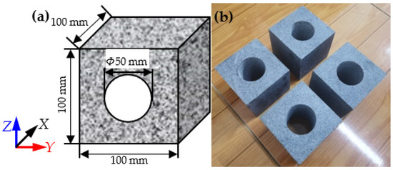
Figure 2.
Granite specimens: (a) schematic of the specimen, (b) image of specimens.
2.2. True-Triaxial Testing Machine
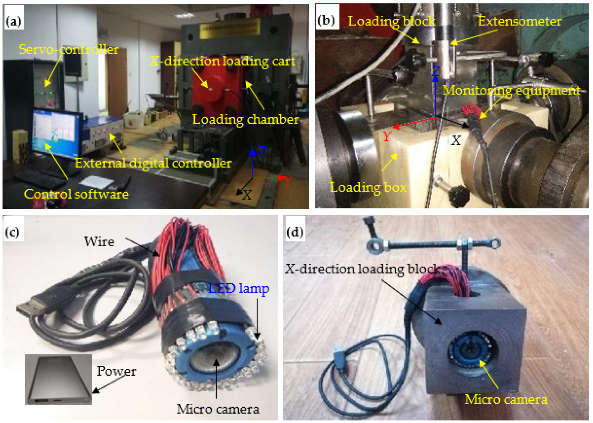
A true-triaxial testing system (Figure 3a,b) was used during the tests, which was introduced in detail in Gong et al. [39,40]. A micro camera (Figure 3c) was used to monitor the failure process of the circular hole sidewall in real time. The combination of the micro camera and the X-direction loading block is shown in Figure 3d. The stress monitoring system is composed of a true-triaxial frame, a servo controller, an external digital controller, a force sensor, a data acquisition instrument, a computer and a rock true-triaxial servo control software. The true-triaxial frame and the loading blocks are composed of high-rigidity metal materials, which have high compressive strength, tensile strength and strong resistance to deformation [47,48,49]. During the test, the experimenter transmits load command to be applied to the servo controller through the computer and rock true-triaxial servo control software, and then it controls the oil pump to apply the corresponding oil pressure, which pushes the loading rod to act on the loading block, and finally realizes sample loading. The force loaded on the sample is transmitted to the external digital controller through the force sensor on the loading rod collected by the data acquisition instrument, and the final test curve is presented on the control software.

Figure 3.
Experimental equipment: (a) true-triaxial testing machine, (b) loading chamber, (c) microcamera, and (d) combination of microcamera and X-direction loading block.
2.3. Initial Stress States at Different Depths
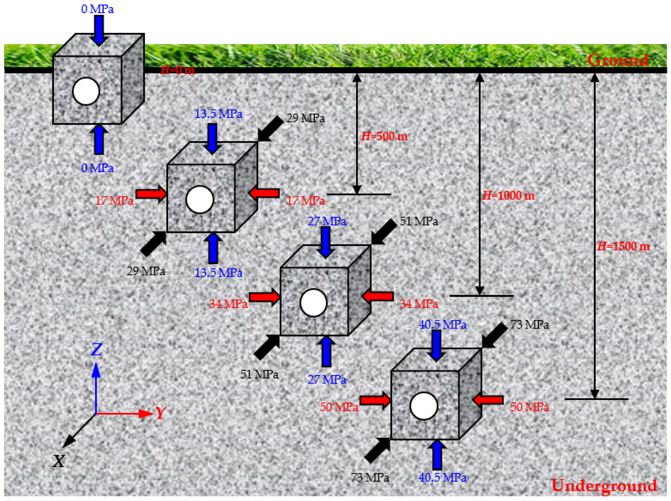
At the depths of 0, 500, 1000, and 1500 m, the initial stress state was determined by the in situ stress calculation Formula (1) [50,51].
where is the vertical stress (MPa), and are the maximum and minimum horizontal stresses (MPa), respectively, H is the depth (m). In the underground rock mass, most of the regions have three-dimensional unequal compressive stress dominated by the vertical and horizontal stresses. Therefore, the initial stress field of three-dimensional unequal compressive stress is set according to the calculations of in situ stress at different depths, as shown in Figure 4. According to the experimental results from Gong et al. [39,40], when the lateral stress is higher, the failure stress of the circular hole sidewall is higher, and the stability of surrounding rock is stronger. The uniaxial compressive strength of the granite selected in this study reaches 261.6 MPa. Under three-dimensional stress, the initial failure stress of surrounding rock is relatively high. However, due to the limitation of stress range of the testing machine, the surrounding rock is difficult to be significantly damaged under high lateral stress. To make the test results more obvious, this study mainly carried out the true-triaxial test in which the X direction stress at different depths serves as the horizontal maximum principal stress σhmax.

Figure 4.
Initial stress states at the depths of 0, 500, 1000, and 1500 m.
3. Experimental Results
3.1. Stress Path and Stress–Time Curves
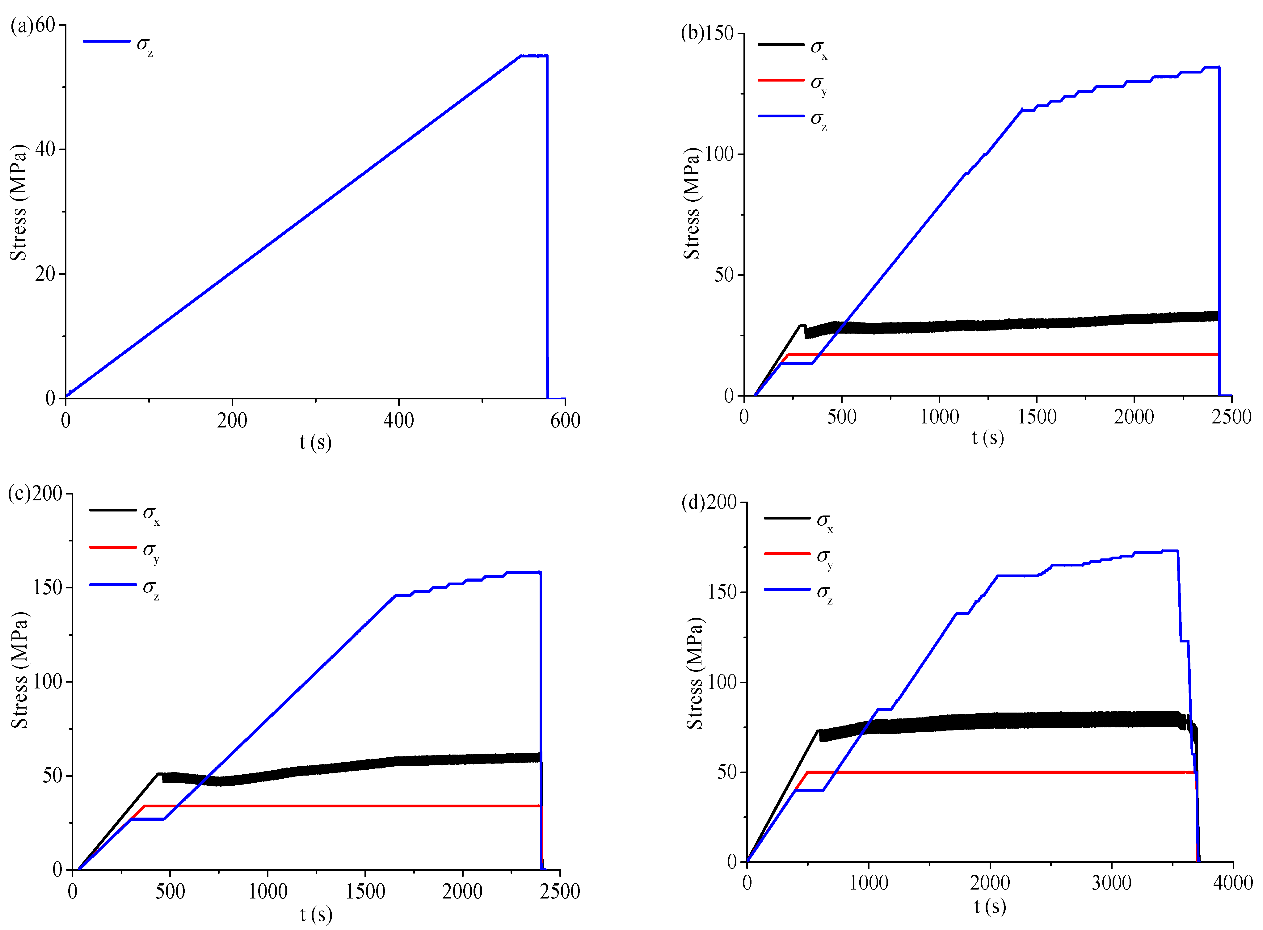
During the test, σx, σy, and σz were increased to the initial stress state under different depths by load control at the loading rate of 1000 N/s. Then, the loading method in the X direction was changed to displacement control, that is, the displacement in the X direction remained unchanged (simulated plane-strain problem). σz continued to increase at the same loading rate. When serious spalling failure occurred on both sidewalls of the circular hole, σz was maintained for a period, and then σx, σy, and σz were decreased to 0 MPa. The stress–time curves at different depths are shown in Figure 5. At the depth of 0 m, the shallow tunnel was simulated, and the horizontal stress was 0 MPa, as shown in Figure 5a. At the depths of 500, 1000, and 1500 m, the initial stress states (σx, σy, σz) were (29, 17, 13.5), (51, 34, 27), and (73, 50, 40.5), respectively. When σx, σy, and σz were increased to the initial stress states by load control, the loading method in the X-direction was changed from force to displacement control, and σx produced slight fluctuation, as shown in Figure 5b–d. When σz was increased to 55 MPa, 136 MPa, 158 MPa, and 173 MPa at the depths of 0, 500, 1000, and 1500 m, σx, σy, and σz were decreased to 0 MPa at the displacement rate of 20 mm/min.
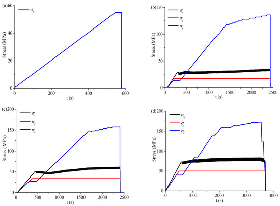
Figure 5.
Stress–time curves at different depths: (a) H = 0 m, (b) H = 500 m, (c) H = 1000 m, and (d) H = 1500 m.
3.2. Failure Process of the Circular Hole Sidewall
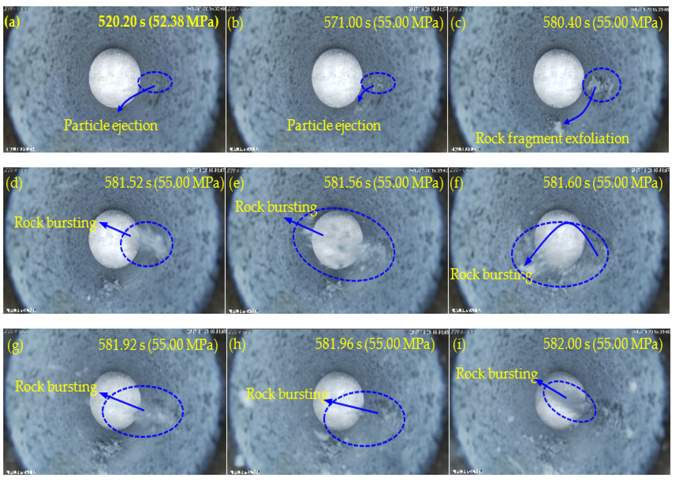
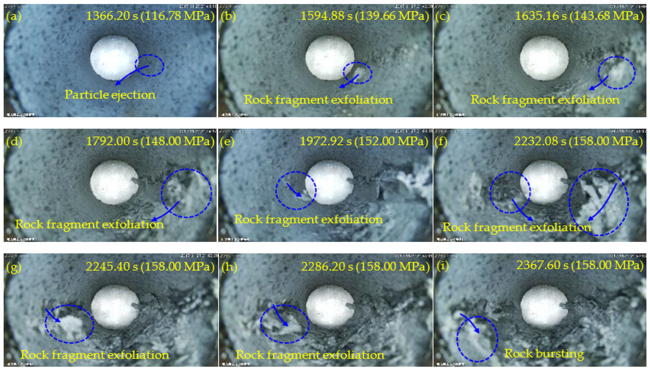
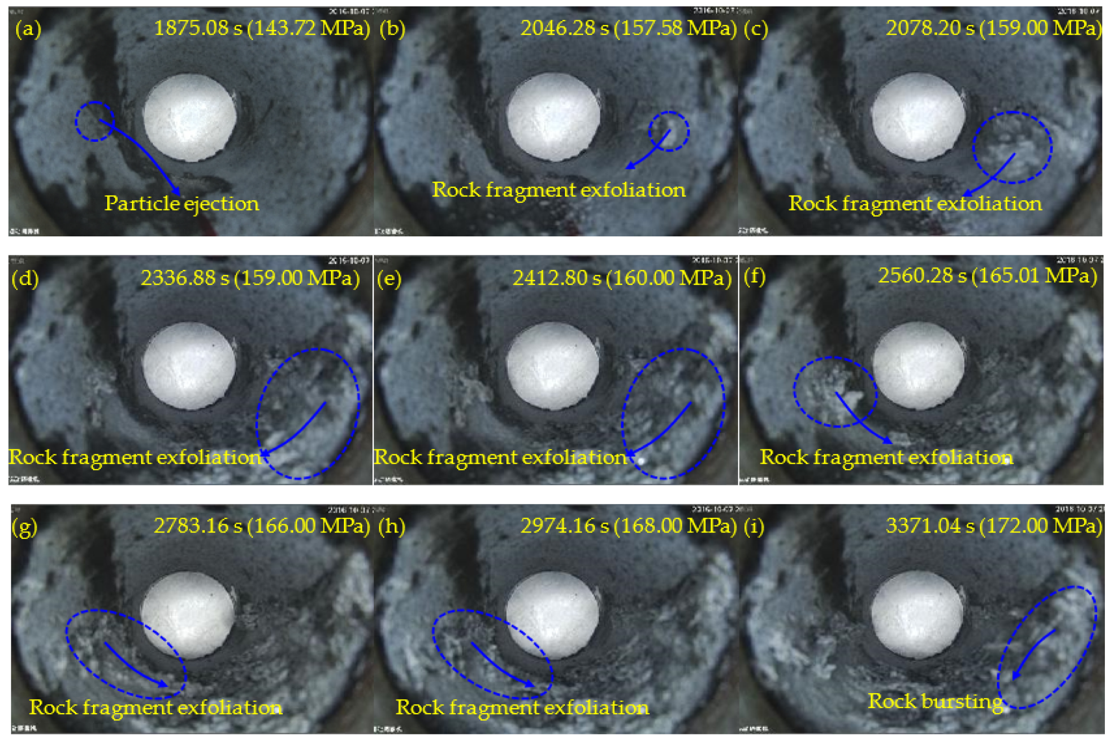
Figure 6, Figure 7, Figure 8 and Figure 9 show the failure processes of the circular hole sidewalls at the depths of 0, 500, 1000, and 1500 m. When H = 0 m, the failure process of sample HK-0-0 is shown in Figure 6. At 520.20 s and when σz = 52.38 MPa, the right sidewall experienced particle ejection, as shown in Figure 6a. When σz was increased to 55.00 MPa and maintained constant, the right sidewall produced particle ejection (Figure 6b), rock fragment exfoliation (Figure 6c), and multiple violent failures (Figure 6d–i). During the violent failure, the right sidewall suffered massive particle ejection and rock fragment exfoliation, as shown in Figure 6d–i. When H = 500 m, the confining pressure was increased to 29 MPa (σx) and 17 MPa (σy). The failure process of sample HK-29-17 is shown in Figure 7. During loading to the initial stress state, no macroscopic failure occurred on the circular hole sidewalls. At 1177.60 s, σz was increased to 99.40 MPa, and fine particle ejection occurred on the right sidewall, as shown in Figure 7a. When σz = 113.57 MPa, the right sidewall produced rock fragment exfoliation (Figure 7b). As σz was continuously increased to 117.99 MPa, the right sidewall produced rock fragment exfoliation (Figure 7c). When σz was loaded to 118.42 MPa, the left sidewall experienced fine particle ejection, as shown in Figure 7d. In Figure 7e, large rock fragment was exfoliated and accompanied by massive particle ejection when σz was increased to 126.00 MPa. As shown in Figure 7f, when σz = 127.99 MPa, the right sidewall produced rock bursting accompanied by massive particle ejection and rock fragment exfoliation. With an increase in σz, two rock fragment exfoliations occurred on the left sidewall, as shown in Figure 7g,h. Finally, when σz = 136.00 MPa, the right sidewall produced rock bursting, and ejected massive particles and rock fragments, as shown in Figure 7i. At the depths of 1000 and 1500 m, the failure processes (Figure 8 and Figure 9) of the circular hole sidewalls were similar to that at the depths of 0 and 500 m. In summary, the failure process at different depths can be divided into four periods: (a) the calm period, (b) the particle ejection period, (c) the rock fragment exfoliation period, and (d) the rock bursting period. The schematic diagrams of the failure process at different stages are shown in Figure 10. With expansion of failure depth, symmetrical V-shaped notches were finally formed on both sidewalls perpendicular to the direction of the maximum principal stress.
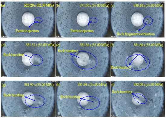
Figure 6.
Failure process at H = 0 m.
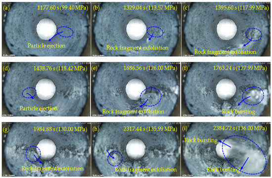
Figure 7.
Failure process at H = 500 m.

Figure 8.
Failure process at H = 1000 m.
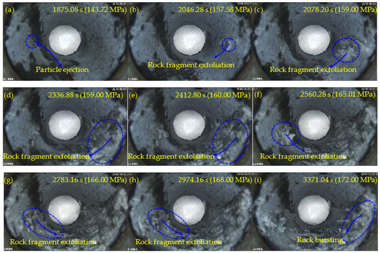
Figure 9.
Failure process at H = 1500 m.
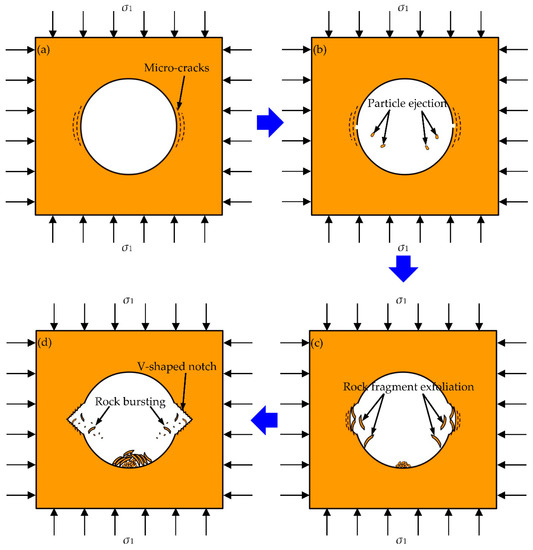
Figure 10.
Schematic diagrams of the four periods of sidewall failure: (a) the calm period, (b) the particle ejection period, (c) the rock fragment exfoliation period, and (d) the rock bursting period [40].
3.3. Failure Characteristics of the Circular Hole Sidewall
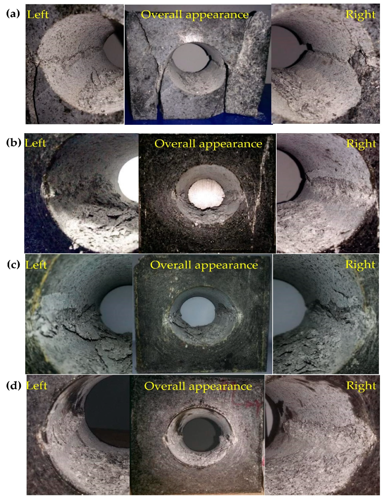
The left and right sidewall failures at different depths are shown in Figure 11. The failure positions of the granite tunnel at the depths of 0, 500, 1000, and 1500 m were distributed in the sidewalls perpendicular to the direction of the maximum principal stress, and symmetrical V-shaped notches were formed on both sidewalls with the increase in the maximum principal stress (vertical stress, σz). During the sidewall failure, the ejected particles and exfoliated rock fragments had a certain speed, indicating that the energy accumulated in the surrounding rock partially transformed the kinetic energy of the rock fragments. From Figure 11, the rock fragments produced by the sidewall failure were mostly distributed at the bottom of the circular hole. Therefore, when the vertical stress is the maximum principal stress, the depth has no effect on the failure position of the surrounding rock in circular hole.

Figure 11.
Photographs of failure at different depths: (a) H = 0 m, (b) H = 500 m, (c) H = 1000 m, and (d) H = 1500 m.
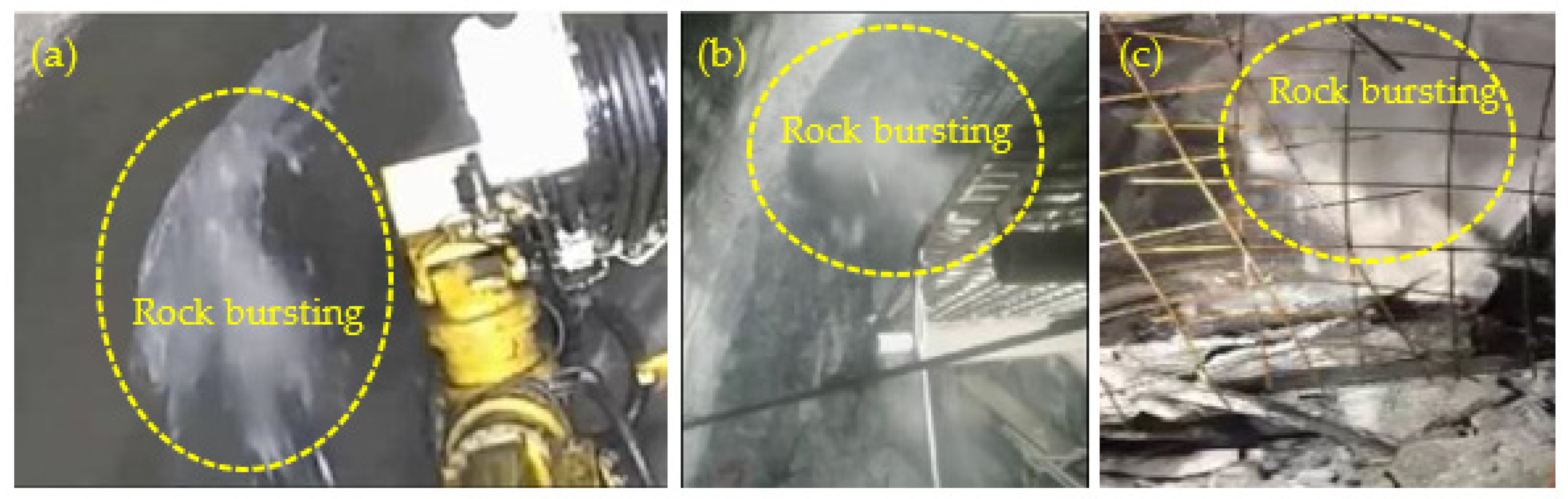
Figure 12 shows the rockburst occurred in the actual engineering. For example, for Bayu Tunnel in Lalin Section of Sichuan–Tibet Railway (Figure 12a), Grand Canyon Tunnel of Sichuan ehan Expressway (Figure 12b), and Qinling Tunnel for the water diversion from the Han to the Wei river project (Figure 12c), the surrounding rock of these tunnels suffered from severe rockburst, and the rock bursting processes were accompanied by massive particle ejection and rock fragment exfoliation. This is consistent with the experimental results in Section 3.2, as shown in Figure 6d–i, Figure 7f,i, Figure 8i and Figure 9i. Therefore, the laboratory simulation tests reproduced the rockburst process of the surrounding rock in a circular tunnel at different depths, and the test results were relatively reliable.
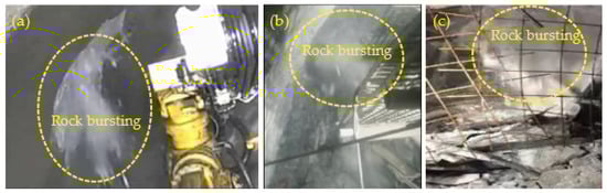
Figure 12.
Photographs of rockburst in the actual engineering: (a) Bayu Tunnel in Lalin Section of Sichuan–Tibet Railway, (b) Grand Canyon Tunnel of Sichuan ehan Expressway, and (c) Qinling Tunnel for the water diversion from the Han to Wei river project.
4. Discussions
4.1. Influence of Depth on Failure Characteristics
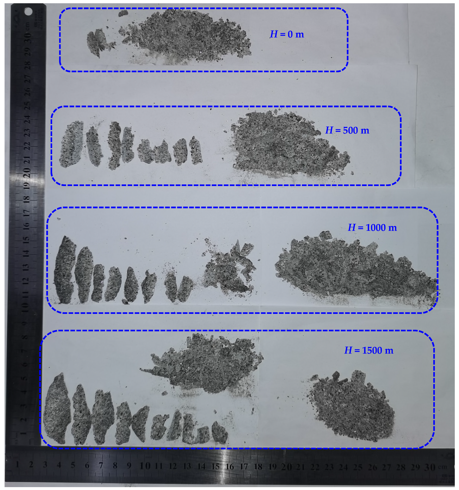
Figure 13 shows the rock fragments produced by the circular hole sidewalls at different depths. When the depth was 0 m, the sidewall failure produced mostly fine rock particles, and the failure range of the left and right sidewalls was relatively small. When H = 500 m, the failure of the left and right sidewalls mostly produced rock fragments showing the characteristics of thick in the middle and thin at the edge. During the rock fragment exfoliation, the sidewall failure also produced some fine particles. By comparison, the failure range at the depth of 500 m was obviously wider than that when H = 0 m, and the size of rock fragments was larger, as shown in Figure 11 and Figure 13. When H = 1000 m, the size of rock fragments further increased and was close to that at the depth of 1500 m. Therefore, within a certain depth range, with increasing depth, the failure range of circular tunnel increased, and the size of rock fragments increased. However, the damage range does not always increase with the depth, and there may be a critical value. Since only four depths were carried out in this study, more experimental studies are needed to determine the critical depth.
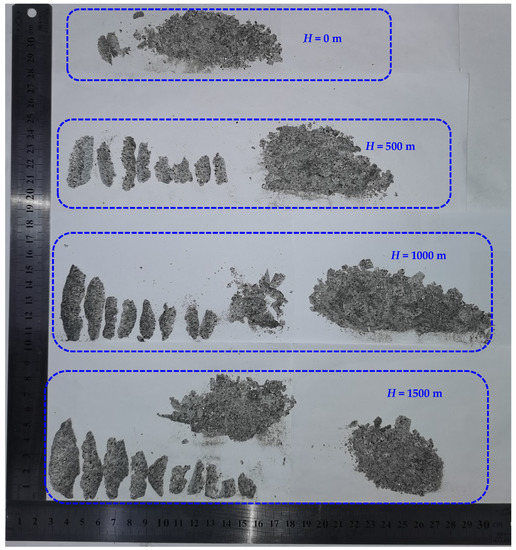
Figure 13.
Rock fragments produced by the circular hole sidewall at different depths.
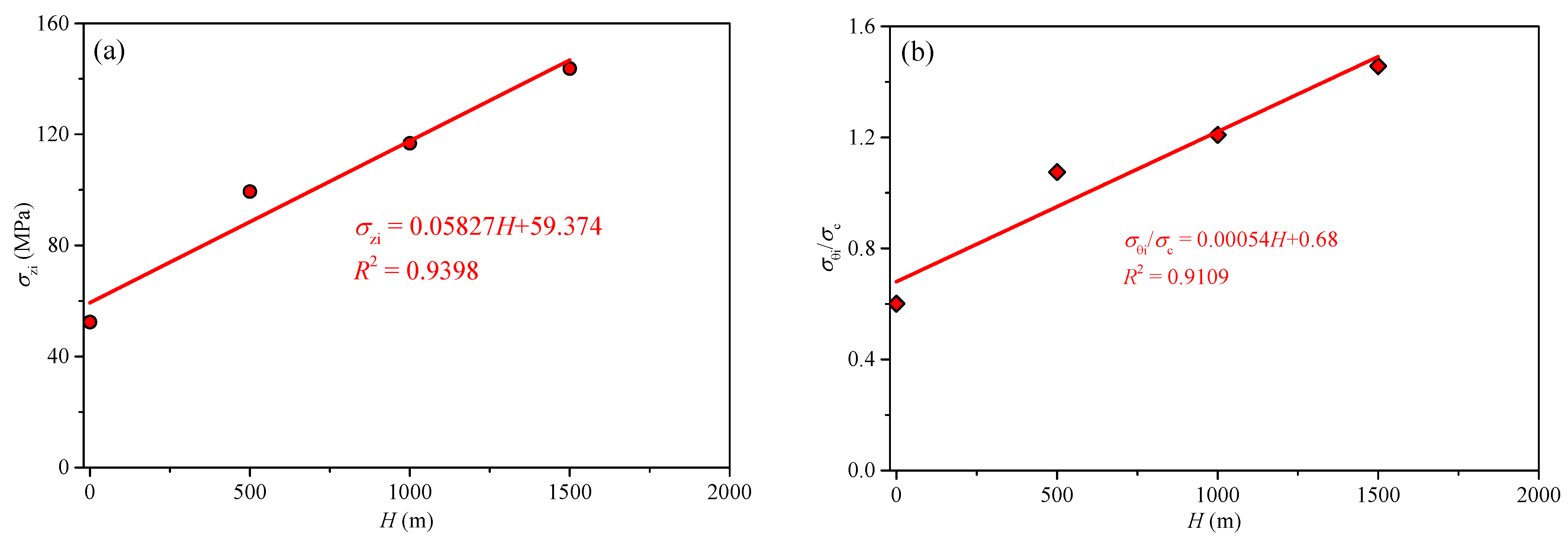
Figure 14a shows the initial failure vertical stress σzi of circular hole sidewalls at different depths. It shows that σzi increased linearly with the increase in depth. The main reason was that the three-dimensional unequal stress state of the surrounding rock gradually increased with the increase in depth, which in turn led to an increase in the strength and stability of the surrounding rock. Therefore, the fundamental reason for the change in surrounding rock stability at different depths is the change in the stress state. To analyze stress distribution in the surrounding rock of a circular tunnel, it is assumed that the rock mass before failure is elastic. According to Kirsch solution, the maximum tangential stress σθi is distributed on the left and right sidewalls. Therefore, results of σθi = 3σzi−σy, and σθi/σc (σc is the uniaxial compressive strength) can be obtained and listed in Table 1. When the sidewall produced initial failure, the range of σθi/σc was from 0.60 to 1.46 at the depths of 0, 500, 1000, and 1500 m, as shown in Figure 14b. The test results agree with those of Dowding and Andersson [52]. From Figure 14b, it is noted that the σθi/σc increases linearly with depth.
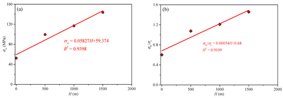
Figure 14.
Stress characteristics of initial sidewall failure at different depths: (a) relationship between σzi and H; (b) relationship between σθi/σc and H.

Table 1.
Stress characteristics of initial sidewall failure at different depths.
4.2. Influence of Depth on Rockburst Severity
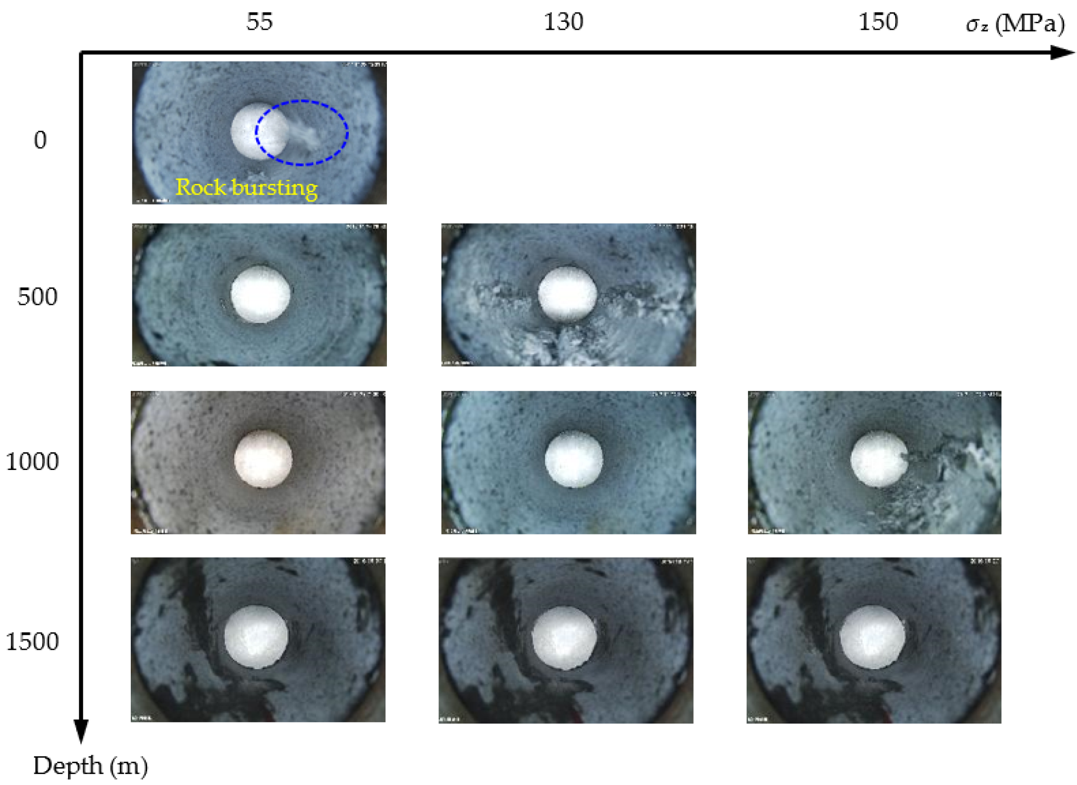
To compare the failure severity of surrounding rock in the circular tunnel at different depths, the failure photographs of the sidewalls were selected when the vertical stress was adjusted to 55, 130, and 150 MPa, as shown in Figure 15. When σz = 55 MPa, a violent rockburst occurred on the circular hole sidewall, and the right sidewall produced massive particle ejection and rock fragment exfoliation at the depth of 0 m. At the depths of 500, 1000, and 1500 m, there was no macroscopic failure on the surrounding rock. By comparison, the rockburst of the surrounding rock in the circular tunnel was the most severe at the depth of 0 m. Since there was no confinement effect of confining pressure at the depth of 0 m, the bearing capacity of the specimen was low, and the vertical stress was below 130 MPa. Therefore, when σz = 130 MPa, the failure photographs of the sidewalls at the depths of 500, 1000 and 1500 m were taken. The left and right sidewalls at the depth of 500 m produced severe failure, and cracks approximately penetrated the entire sample along the axis of the circular hole. At the depth of 1000 m, slight particle ejection occurred on the right sidewall, but no macroscopic failure occurred on the left sidewall. At the depth of 1500 m, no macroscopic failure occurred on the surrounding rock. Since the confining pressure at the depth of 500 m was lower than that at the depths of 1000 and 1500 m, the bearing capacity of the specimen was lower, and the failure at the depth of 500 m was more severe than that at the depths of 1000 and 1500 m. Finally, the vertical stress was not increased to 150 MPa. Therefore, when σz = 150 MPa, the failure photographs of the sidewalls at the depths of 1000 and 1500 m were taken. Severe failure occurred on the right sidewall at the depth of 1000 m, in which cracks approximately penetrated the entire sample along the axis of the circular hole. At a depth of 1500 m, slight particle ejection occurred on the left and right sidewalls in the circular tunnel. By comparison, the failure at the depth of 1000 m was significantly more severe than that at the depth of 1500 m. In summary, when the vertical stress was adjusted to the same stress level, with the increase in depth, the failure severity of the surrounding rock in the circular tunnel gradually decreased. However, when the vertical stress was adjusted to a higher stress level, the failure range of the surrounding rock of the circular tunnel was wider with the increase in depth. Therefore, the support range of the surrounding rock should be increased as the depth increased to improve the overall stability of the surrounding rock and reduce the failure range.
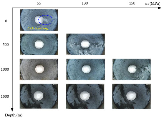
Figure 15.
Failure of the circular hole sidewall under different depths and vertical stresses.
4.3. Reliability and Repeatability of Test Results
Generally, to ensure the accuracy and reliability of experimental results, three tests should be conducted under the same state. However, due to the limited number of granite samples collected from the site, only four cube samples with a circular hole were left and prepared for tests of this paper. To study the influence of depth on the failure process and characteristics of the surrounding rock in a circular tunnel, we carried out experiments at four depths. Due to the limited number of samples, we set the lateral stress as the minimum horizontal principal stress and the hole axis stress as the maximum horizontal principal stress at each depth. Then, true-triaxial tests were conducted at different depths. We illustrate the reliability and repeatability of the experimental results in this study from the following aspects.
(1) At different depths, although the stress state of the surrounding rock has changed, the failure process of the surrounding rock is similar and can be divided into four stages: (a) the calm period, (b) the particle ejection period, (c) the rock fragment exfoliation period, (d) the rock bursting period. Therefore, the results show the repeatability and reliability of the failure process of the circular tunnel surrounding rock in this manuscript.
(2) After the tests, V-shaped notches were formed on the left and right sidewalls in the circular tunnel (Figure 11), which is similar to the failure characteristics in the actual project. For example, spalling in the roof and floor of a circular test tunnel in the underground research laboratory [53], and mild spalling in the sidewalls of a vertical raise bored shaft in an underground mine [54]. This indicates that the test results are consistent with the actual project.
(3) The rock fragments produced by the failure of the tunnel sidewall were mostly thin slices and wedges (Figure 13), which were similar to that produced by rockbursts in a transport roadway at 500 m in Linglong gold mine (Figure 16).
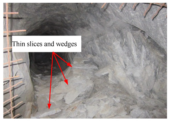
Figure 16.
Rock fragments in a transport roadway at 500 m in Linglong gold mine, China.
(4) According to the test results, with the increase in depth, the three-dimensional unequal stress state of the surrounding rock gradually increased; the failure range and the size of rock fragments increased, and the initial failure vertical stress linearly increased, the strength and stability of the surrounding rock were enhanced. Therefore, the fundamental reason for the change in surrounding rock stability at different depths is the change in the stress state. The test results did not show abnormal data, so the test results are more reliable.
In summary, although only one experiment is carried out for each working condition in this study, the test results are repeatable and reliable.
5. Conclusions
(1) The failure process at different depths can be divided into four periods: (a) the calm period, (b) the particle ejection period, (c) the rock fragment exfoliation period, and (d) the rock bursting period. With expansion of the failure depth, symmetrical V-shaped notches were finally formed on both sidewalls perpendicular to the direction of the maximum principal stress. The failure characteristics were consistent with the spalling failure observed in underground engineering.
(2) With an increase in depth, the three-dimensional unequal stress state of the surrounding rock gradually increased, the failure range and the size of rock fragments increased, the initial failure vertical stress linearly increased, and the strength and stability of the surrounding rock were enhanced. Therefore, the fundamental reason for the change in surrounding rock stability at different depths is the change in the stress state.
(3) When the vertical stress was adjusted to the same stress level, with an increase in depth, the failure severity of surrounding rock in the circular tunnel gradually decreased. However, when the vertical stress was adjusted to a higher stress level, the failure range was wider with increasing depth. Therefore, the support range of the surrounding rock should be increased as the depth increased to improve the overall stability of the surrounding rock and reduce the failure range.
Author Contributions
X.S.: validation, investigation, data curation, writing—review and editing. K.P.: resources, review and editing, supervision, funding support. S.L.: acquisition of data, review and editing. All authors have read and agreed to the published version of the manuscript.
Funding
This research received no external funding.
Institutional Review Board Statement
Not applicable.
Informed Consent Statement
Not applicable.
Data Availability Statement
All data generated or analyzed during this study are included in this published article.
Acknowledgments
This work was supported by the National Natural Science Foundation of China (Grant No. 51974043).
Conflicts of Interest
The authors declare no conflict of interest.
References
- Cai, M.F.; Brown, E.T. Challenges in the mining and utilization of deep mineral resources. Engineering 2017, 3, 432–433. [Google Scholar] [CrossRef]
- Li, X.B.; Gong, F.Q.; Tao, M.; Dong, L.J.; Du, K.; Ma, C.D.; Zhou, Z.L.; Yin, T.B. Failure mechanism and coupled static-dynamic loading theory in deep hard rock mining: A review. J. Rock Mech. Geotech. Eng. 2017, 9, 767–782. [Google Scholar] [CrossRef]
- Tang, C.A.; Wang, J.M.; Zhang, J.J. Preliminary engineering application of microseismic monitoring technique to rockburst prediction in tunneling of Jinping II project. J. Rock Mech. Geotech. Eng. 2010, 2, 193–208. [Google Scholar] [CrossRef] [Green Version]
- Gong, F.Q.; Wu, W.X.; Zhang, L. Brazilian disc test study on tensile strength-weakening effect of high pre-loaded red sandstone under dynamic disturbance. J. Cent. South Univ. 2020, 27, 2899–2913. [Google Scholar] [CrossRef]
- Wu, W.X.; Gong, F.Q. Strength weakening effect of high prestatically loaded marble subjected to low-frequency dynamic disturbance under point load. Shock. Vib. 2021, 2021, 5529897. [Google Scholar] [CrossRef]
- Peng, K.; Liu, Z.P.; Zou, Q.L.; Zhang, Z.Y.; Zhou, J.Q. Static and dynamic mechanical properties of granite from various burial depths. Rock Mech. Rock Eng. 2019, 52, 3545–3566. [Google Scholar]
- Peng, K.; Liu, Z.P.; Zou, Q.L.; Wu, Q.H.; Zhou, J.Q. Mechanical property of granite from different buried depths under uniaxial compression and dynamic impact: An energy-based investigation. Powder Technol. 2020, 362, 729–744. [Google Scholar] [CrossRef]
- Wang, X.J.; Zhang, H.; Chen, Q.L.; Zeng, Q.; Liu, J. Acoustic emission characteristics and damage model of limestone loading with different rockburst tendencies. Chin. J. Rock Mech. Eng. 2022. (In Chinese) [Google Scholar] [CrossRef]
- He, M.C.; Xie, H.P.; Peng, S.P.; Jiang, Y.D. Study on rock mechanics in deep mining engineering. Chin. J. Rock Mech. Eng. 2005, 24, 2803–2813. (In Chinese) [Google Scholar]
- Gao, M.Z.; Zhang, R.; Xie, J.; Peng, G.Y.; Yu, B.; Ranjith, P.G. Field experiments on fracture evolution and correlations between connectivity and abutment pressure under top coal caving conditions. Int. J. Rock Mech. Min. Sci. 2018, 111, 84–93. [Google Scholar] [CrossRef]
- Xie, H.P.; Gao, M.Z.; Zhang, R.; Peng, G.Y.; Wang, W.Y.; Li, A.Q. Study on the mechanical properties and mechanical response of coal mining at 1000 m or deeper. Rock Mech. Rock Eng. 2019, 52, 1475–1490. [Google Scholar] [CrossRef]
- Pu, Y.Y.; Apel, D.B.; Liu, V.; Mitri, H. Machine learning methods for rockburst prediction-state-of-the-art review. Int. J. Min. Sci. Technol. 2019, 29, 565–570. [Google Scholar] [CrossRef]
- Wang, Y.C.; Tang, C.A.; Tang, L.X.; Zhang, S.C.; Li, L.M.; Li, Y.B.; Duan, W.S. Microseismicity characteristics before and after a rockburst and mechanisms of intermittent rockbursts in a water diversion tunnel. Rock Mech. Rock Eng. 2022, 55, 341–361. [Google Scholar] [CrossRef]
- Huang, R.Q.; Wang, X.N. Analysis of dynamic disturbance on rock burst. Bull. Eng. Geol. Environ. 1999, 57, 281–284. [Google Scholar] [CrossRef]
- Si, X.F.; Li, X.B.; Gong, F.Q.; Huang, L.Q.; Liu, X.L. Experimental investigation of failure process and characteristics in circular tunnels under different stress states and internal unloading conditions. Int. J. Rock Mech. Min. Sci. 2022, 154, 105116. [Google Scholar] [CrossRef]
- Keneti, A.; Sainsbury, B.A. Review of published rockburst events and their contributing factors. Eng. Geol. 2018, 246, 361–373. [Google Scholar] [CrossRef]
- Makowski, P.; Niedbalski, Z. A comprehensive geomechanical method for the assessment of rockburst hazards in underground mining. Int. J. Min. Sci. Technol. 2020, 30, 345–355. [Google Scholar] [CrossRef]
- Gong, F.Q.; Pan, J.F.; Jiang, Q. The difference analysis of rockburst and coal burst and key mechanisms of deep engineering geological hazards. J. Eng. Geol. 2021, 29, 933–961. [Google Scholar]
- Gong, F.Q.; Luo, S.; Jiang, Q.; Xu, L. Theoretical verification of the rationality of strain energy storage index as rockburst criterion based on linear energy storage law. J. Rock Mech. Geotech. Eng. 2022. [Google Scholar] [CrossRef]
- Martin, C.D.; Kaiser, P.K.; Mccreath, D.R. Hoek-Brown parameters for predicting the depth of brittle failure around tunnels. Can. Geotech. J. 1999, 36, 136–151. [Google Scholar] [CrossRef]
- Hajiabdolmajid, V.; Kaiser, P.K.; Martin, C.D. Modelling brittle failure of rock. Int. J. Rock Mech. Min. Sci. 2002, 39, 731–741. [Google Scholar] [CrossRef]
- Si, X.F.; Huang, L.Q.; Gong, F.Q.; Li, X.B. Failure Process and Characteristics of Three-Dimensional High-Stress Circular Tunnel under Saturated Water Content. Transactions of Nonferrous Metals Society of China. 2022. Available online: https://kns.cnki.net/kcms/detail/43.1239.TG.20220301.1815.030.html (accessed on 3 March 2022).
- Feng, X.T. Rockburst: Mechanism, Monitoring, Warning and Mitigation; Elsevier-Health Sciences Division: Amsterdam, The Netherlands, 2017. [Google Scholar]
- Li, P.X.; Feng, X.T.; Feng, G.L.; Xiao, Y.X.; Chen, B.R. Rockburst and microseismic characteristics around lithological interfaces under different excavation directions in deep tunnels. Eng. Geol. 2019, 260, 105209. [Google Scholar] [CrossRef]
- Zhang, C.Q.; Feng, X.T.; Zhou, H.; Qiu, S.L.; Wu, W.P. Case histories of four extremely intense rockbursts in deep tunnels. Rock Mech. Rock Eng. 2012, 45, 275–288. [Google Scholar] [CrossRef]
- Si, X.F.; Gong, F.Q. Strength-weakening effect and shear-tension failure mode transformation mechanism of rockburst for fine-grained granite under triaxial unloading compression. Int. J. Rock Mech. Min. Sci. 2020, 131, 104347. [Google Scholar] [CrossRef]
- Zhang, T.; Hu, J.Y.; Lin, F.; Li, S.L.; Yang, D.Y.; Yu, Z.F.; Gao, W. Study on occurrence law and prevention measures of rock burst with high stress characteristic in kilometer deep well of metal mine. Min. Technol. 2017, 17, 28–32. (In Chinese) [Google Scholar]
- Lee, S.M.; Park, B.S.; Lee, S.W. Analysis of rockbursts that have occurred in a waterway tunnel in Korea. Int. J. Rock Mech. Min. Sci. 2004, 41, 911–916. [Google Scholar] [CrossRef]
- Read, R.S. 20 years of excavation response studies at AECL’s Underground Research Laboratory. Int. J. Rock Mech. Min. Sci. 2004, 41, 1251–1275. [Google Scholar] [CrossRef]
- Zhou, H.; Meng, F.Z.; Zhang, C.Q.; Hu, D.W.; Yang, F.J.; Lu, J.J. Analysis of rockburst mechanisms induced by structural planes in deep tunnels. Bull. Eng. Geol. Environ. 2015, 74, 1435–1451. [Google Scholar] [CrossRef]
- Sun, X.M.; Xu, H.C.; He, M.C.; Zhang, F. Experimental investigation of the occurrence of rockburst in a rock specimen through infrared thermography and acoustic emission. Int. J. Rock Mech. Min. Sci. 2017, 93, 250–259. [Google Scholar] [CrossRef]
- Feng, F.; Li, X.B.; Luo, L.; Zhao, X.D.; Chen, S.J.; Jiang, N.; Huang, W.P.; Wang, Y.J. Rockburst response in hard rock owing to excavation unloading of twin tunnels at great depth. Bull. Eng. Geol. Environ. 2021, 80, 7613–7631. [Google Scholar] [CrossRef]
- Singh, S.P. The influence of rock properties on the occurrence and control of rockbursts. Min. Sci. Technol. 1987, 5, 11–18. [Google Scholar] [CrossRef]
- Singh, S.P. Classification of mine workings according to their rockburst proneness. Min. Sci. Technol. 1989, 8, 253–262. [Google Scholar] [CrossRef]
- Si, X.F.; Huang, L.Q.; Gong, F.Q.; Liu, X.L.; Li, X.B. Experimental investigation on influence of loading rate on rockburst in deep circular tunnel under true-triaxial stress condition. J. Cent. South Univ. 2020, 27, 2914–2929. [Google Scholar] [CrossRef]
- Si, X.F.; Huang, L.Q.; Li, X.B.; Gong, F.Q.; Liu, X.L. Mechanical properties and rockburst proneness of phyllite under uniaxial compression. Trans. Nonferrous Met. Soc. China 2021, 31, 3862–3878. [Google Scholar] [CrossRef]
- Hu, X.C.; Su, G.S.; Chen, G.Y.; Mei, S.M.; Feng, X.T.; Mei, G.X.; Huang, X.H. Experiment on rockburst process of borehole and its acoustic emission characteristics. Rock Mech. Rock Eng. 2019, 52, 783–802. [Google Scholar] [CrossRef]
- Wu, H.; Ma, D.; Spearing, A.J.S.; Zhao, G.Y. Fracture response and mechanisms of brittle rock with different numbers of openings under uniaxial loading. Geomech. Eng. 2021, 25, 481–493. [Google Scholar]
- Gong, F.Q.; Luo, Y.; Li, X.B.; Tao, M.; Si, X.F. Experimental simulation investigation on rockburst induced by spalling failure in deep circular tunnels. Tunn. Undergr. Space Technol. 2018, 81, 413–427. [Google Scholar] [CrossRef]
- Gong, F.Q.; Si, X.F.; Li, X.B.; Wang, S.Y. Experimental investigation of strain rockburst in circular caverns under deep three-dimensional high-stress conditions. Rock Mech. Rock Eng. 2019, 52, 1459–1474. [Google Scholar] [CrossRef]
- Luo, Y.; Gong, F.Q.; Li, X.B.; Wang, S.Y. Experimental simulation investigation of influence of depth on spalling characteristics in circular hard rock tunnel. J. Cent. South Univ. 2020, 27, 891–910. [Google Scholar] [CrossRef]
- Luo, S.; Gong, F.Q. Linear energy storage and dissipation laws of rocks under preset angle shear conditions. Rock Mech. Rock Eng. 2020, 53, 3303–3323. [Google Scholar] [CrossRef]
- Feng, X.T.; Haimson, B.; Li, X.C.; Chang, C.D.; Ma, X.D.; Zhang, X.W.; Ingraham, M.; Suzuki, K. ISRM Suggested Method: Determining deformation and failure characteristics of rocks subjected to true triaxial compression. Rock Mech. Rock Eng. 2019, 52, 2011–2020. [Google Scholar] [CrossRef]
- Lyons, P.C. IUGS classification of granitic rocks: A critique. Geology 1976, 4, 425–426. [Google Scholar] [CrossRef]
- Gong, F.Q.; Yan, J.Y.; Li, X.B. A new criterion of rock burst proneness based on the linear energy storage law and the residual elastic energy index. Chin. J. Rock Mech. Eng. 2018, 37, 1993–2014. [Google Scholar]
- Gong, F.Q.; Yan, J.Y.; Li, X.B.; Luo, S. A peak-strength strain energy storage index for rock burst proneness of rock materials. Int. J. Rock Mech. Min. Sci. 2019, 117, 76–89. [Google Scholar] [CrossRef]
- Shcherbakov, S.S. State of volumetric damage of tribo-fatigue system. Strength Mater. 2013, 45, 171–178. [Google Scholar] [CrossRef]
- Bahdanovich, A.; Bendikiene, R.; Cesnavicius, R.; Ciuplys, A.; Grigas, V.; Jutas, A.; Marmysh, D.; Mazaleuski, A.; Nasan, A.; Shemet, L.; et al. Research on tensile behaviour of new structural material MoNiCa. Mater. Sci. 2019, 25, 292–296. [Google Scholar] [CrossRef] [Green Version]
- Bendikiene, R.; Bahdanovich, A.; Cesnavicius, R.; Ciuplys, A.; Grigas, V.; Jutas, A.; Marmysh, D.; Nasan, A.; Shemet, L.; Sherbakov, S.; et al. Tribo-fatigue behavior of austempered ductile iron MoNiCa as new structural material for rail-wheel system. Mater. Sci. 2020, 26, 432–437. [Google Scholar] [CrossRef]
- Brown, E.T.; Hoek, E. Trends in relationships between measured in-situ stresses and depth. Int. J. Rock Mech. Min. Sci. Geomech. 1978, 15, 211–215. [Google Scholar] [CrossRef]
- Stephansson, O.; Särkkä, P.; Myrvang, A. State of stress in Fennoscandia. In Proceedings of the Rock Stress and Rock Stress Measurement, Stockholm, Sweden, 1–3 September 1986; pp. 21–32. [Google Scholar]
- Dowding, C.H.; Andersson, C.A. Potential for rock bursting and slabbing in deep caverns. Eng. Geol. 1986, 22, 265–279. [Google Scholar] [CrossRef]
- Cai, M.; Kaiser, P.K. Assessment of excavation damaged zone using micromechanics model. Tunn. Undergr. Space Technol. 2005, 20, 301–310. [Google Scholar] [CrossRef]
- Hoek, E.; Kaiser, P.K.; Bawden, W.F. Support of Underground Excavations in Hard Rock; Balkema, A.A., Ed.; CRC Press: Rotterdam, The Netherlands, 1998. [Google Scholar]


Publisher’s Note: MDPI stays neutral with regard to jurisdictional claims in published maps and institutional affiliations. |
© 2022 by the authors. Licensee MDPI, Basel, Switzerland. This article is an open access article distributed under the terms and conditions of the Creative Commons Attribution (CC BY) license (https://creativecommons.org/licenses/by/4.0/).