
DRiPLOF: An RPL Extension for Multi-Interface Wireless Sensor Networks in Interference-Prone Environments


Abstract
1. Introduction
- The definition of a rule-set for a new RPL OF called the Dual-Radio interface routing Protocol for LLNs Objective Function (DRiPLOF), which enables true multi-interface operation and provides a good balance between reliability and end-to-end latency, as well as an implementation of DRiPLOF and of another multi-interface capable OF derived from the work of Lemercier et al. [9,10] (see Section 3).
- Modifications and additions to the Contiki-NG [12] operating system (see Section 5.1), which not only bring it closer to 100% compliance with relevant standards [4,11], but also enables tracking of interface-level statistics, making it easier to develop new OFs for RPL networks with multi-interfaced devices.
- Modifications and additions to the Cooja network simulator [13] and the Cooja radio driver for Contiki-NG, allowing anyone to simulate multi-interfaced nodes running a complete protocol stack of their own design.
- Radio drivers for certain physical platforms (e.g., the Zolertia ReMote [14]), such that a newly developed OF may be deployed across a network of multi-interfaced RPL nodes immediately after the simulation stage.
2. Routing Protocol for LLNs
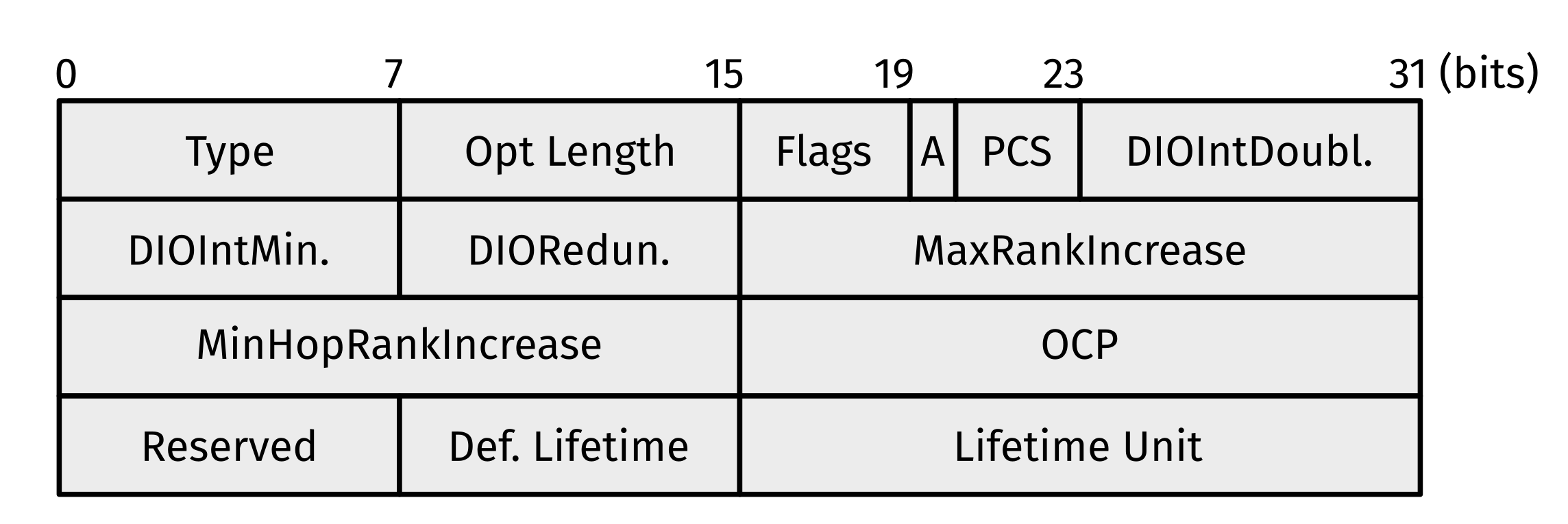
“This information is configured at the DODAG root and distributed throughout the DODAG with the DODAG Configuration option. Nodes other than the DODAG root MUST NOT modify this information.”[4] (p. 52)
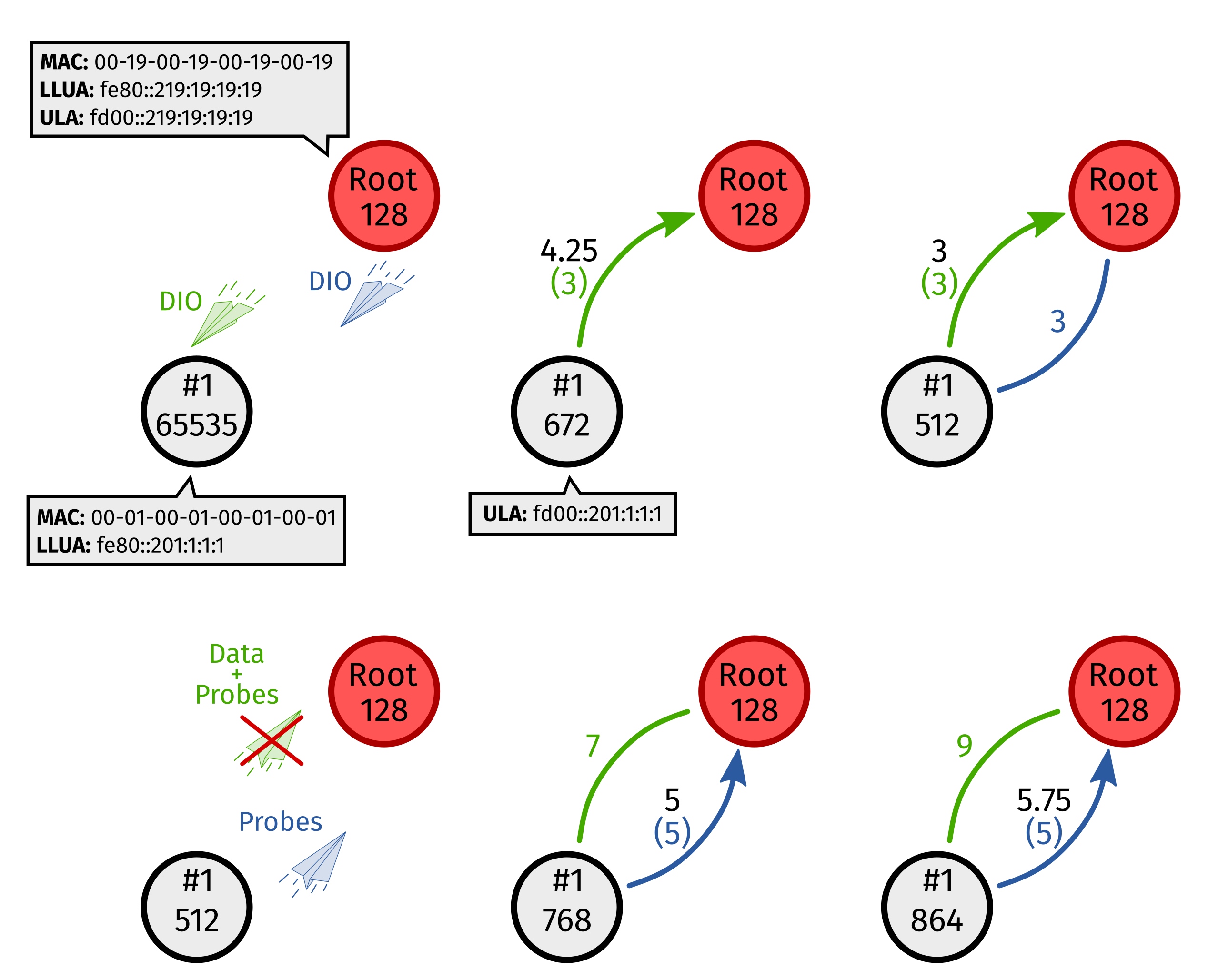
2.1. Node Rank
2.2. Upward Topology Construction and Maintenance
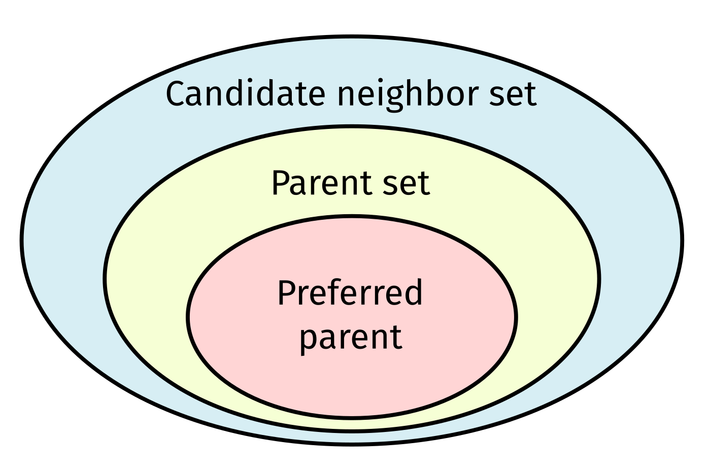
- All candidate parents must belong to the same DODAG version as the node itself.
- Within a DODAG version, a node’s advertised rank must be greater than the rank advertised by any of its parent set members.
| the rank of node n if it would choose node c as its preferred parent; | |
| the advertised rank of candidate neighbor c; | |
| the rank increase associated with the direct path between nodes c and n (typically a routing metric). |
2.3. Downward Traffic
2.3.1. Non-Storing Mode
2.3.2. Storing Mode
3. Related Work
- The MI solution requires one RPL Instance per interface type. Since a node can only belong to one DODAG per instance, belonging to multiple DODAGs means joining multiple instances (each governed by an OF). The OFs can then be tailored to interface types. As such, the main advantage of the MI approach is that it can reuse a generic RPL implementation with a per-technology OF. However, to prevent loops, packets may only switch once between instances to a higher RPLInstanceID. Hence, the MI approach can handle only one link failure along a path and packet switching is uni-directional. In contrast, the proposed PO and IO solutions leverage multi-interfaced nodes in a single DODAG.
- The PO solution is based on OF0 (see Section 2.2). It defines as the average link metric to a neighbor calculated over all interfaces. If an interface is unavailable, its link metric defaults to a fixed maximum value during averaging. Thus, a neighbor incurs a penalty for each interface through which it is unavailable. Unlike OF0, the parent set size is unlimited. The parent yielding the lowest computed rank still becomes the preferred parent, except when there already is one, and one of its interfaces becomes unavailable. Then, metric averaging for the preferred parent is deferred by one OF call. This delay aims to prevent DODAG instability. Note that the interface providing the best link metric towards a neighbor becomes the default interface for (unicast) communication with said neighbor, i.e., it becomes the preferred interface. Preferred interface selection is transparent to RPL. Lemercier et al.’s [9,10] addressing architecture is rather vague. The authors simply stated that “the PO solution combines multiple links into a single virtual link” [9] (p. 2). To the best of our understanding (no code was available for further examination), this means that each node owns a single link-layer address and a single routable and link-local IPv6 address, regardless of how many interfaces it possesses. Assuming each node possesses the same set of interfaces, in order for this to work, each node may possess at most one interface of a given type. Hence, when receiving a message from a given neighbor, it can uniquely identify the neighbor’s originating interface. Furthermore, we assume that each node keeps a single neighbor cache, a single default router list, and a single routing table and that each node (conceptually) tracks a single candidate neighbor set and parent set, respectively. Nodes presumably advertise the same rank across all interfaces. Conveniently, with one link-layer address per node and a single neighbor cache, the PO solution can work with 6LoWPAN ND [7,8], as-is. In addition, both storing and non-storing mode (Section 2.3) would work since nodes are the addressable entities and the default router list and routing table are node-scope as well.
- The IO proposal views each interface as an independent entity. To this extent, a node keeps track of candidate neighbor tuples (nodeID, interfaceID) and, for each physical neighbor, considers only the tuple with the best link quality for addition to the parent set (based on DODAG version and advertised rank) and subsequent rank computation (1). Rank computation remains largely identical, only now, is defined as the link metric of the selected tuple. From the parent set, the neighbor tuple with the lowest computed rank becomes preferred. Note that, contrary to the PO solution, there is no stability mechanism preventing erratic preferred parent changes upon link failures. The absence of any sort of stability mechanism, combined with the fact that every interface is a separate neighbor, is shown to lead to DODAG instability.
4. The Dual-Radio Interface Routing Protocol for LLNs
4.1. Provisions for Multi-Interfaced Operation
- Physical nodes, not their interfaces, are the RPL neighbors.
- Physical nodes are the addressable entities, meaning: (1) all IPv6 addresses are node-scope; and (2) each node has one link-layer address, common to all interfaces.
- Each node may have at most one interface of a given type, allowing it to uniquely identify from which of its neighbor’s interfaces a packet originated.
- Each node owns the same set of interfaces or is otherwise aware of the interfaces it should possess (through a mechanism that is out of this paper’s scope).
- Broadcast DIOs must be sent on all interfaces.
- Unicast DIOs, when sent in response to a DIS, must be sent on the same interface as the incoming DIS.
- Unicast DIOs used for freshness probing (Appendix B) must be sent on all interfaces.
- Otherwise, unicast DIOs must be sent via the preferred interface towards a neighbor.
- Unicast DAOs must be sent to DAO parents via the preferred interface towards those parents.
- DAO Acknowledgments (ACKs), which are always unicast in response to a unicast DAO, must be sent on the same interface as the incoming DAO.
- Broadcast DISs must be sent on all interfaces.
- Unicast DISs used for freshness probing (Appendix B) must be sent on all interfaces.
- Otherwise, unicast DISs must be sent via the preferred interface towards a neighbor.
4.2. Inferred Metrics and Preferred Interface Selection
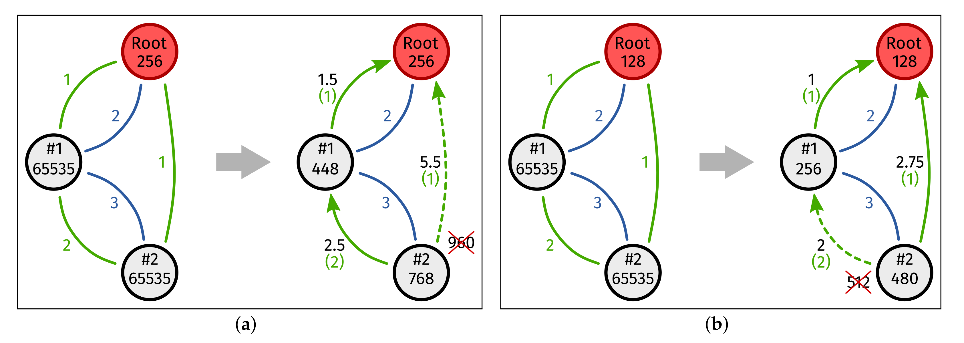
4.3. Parent Selection and Rank Computation
| W | the virtual link metric normalization weight; |
| the number of interfaces per node; | |
| the number of valid physical links towards a given neighbor; | |
| the max number of invalid physical links towards any neighbor, must be and ; | |
| a constant divider, must be ; | |
| the normalized metric of the virtual link towards a given neighbor; | |
| S | a constant scale multiplier; |
| inferred metric of the preferred physical link towards a given neighbor. |
4.4. Theoretical Comparison with POOF
5. Implementation and Simulation Setup
5.1. Multi-Interface Support for Contiki-NG
- A multi-interface radio driver for Zolertia Zoul-based [32] platforms, which serves as an abstraction of underlying radio drivers, as well as a reworked Cooja radio driver based on the same abstraction principles.
- A MAC layer adapted from the Contiki-NG Carrier-Sense Multiple Access (CSMA) MAC layer to accommodate the newly developed radio-driver semantics. We did not alter the original MAC protocol as such, but rather, enabled (near) independent MAC layer functionality for every interface.
- Source files for POOF and DRiPLOF.
- An extension to the Contiki-NG link stats module, which enables multi-interfaced operation. The link stats module is now also responsible for: (1) tracking inferred metrics/interface availability; (2) performing preferred interface selection; (3) performing metric normalization and presenting the result to an OF source file; and (4) tracking the freshness (≠availability) of interfaces.
- A major rework of Contiki-NG’s RPL-Classic routing layer such that it complies with RFC 6719 [11] (Section 3.3) when used with MRHOF and MRHOF-derived OFs (such as DRiPLOF).
- A new probing target selection algorithm and parent selection algorithm such that they now factor in the freshness of interfaces when deciding which neighbor to probe/select as a preferred parent. You can read more about probing and its relation to interface freshness tracking in Appendix B.
5.2. Modifying Cooja to Support Multi-Interfaced Simulations
| the packet delivery ratio | ||
| the received signal strength indicator | ||
| the RSSI for which | ||
| e | Euler’s constant |
| the path loss at distance d from the transmitter | ||
| d | a given distance from the transmitter | |
| the path loss at distance from the transmitter | ||
| a close-in (far-field) reference distance from the transmitter | ||
| an empirically determined path loss exponent | ||
| random variable with Gaussian distribution, zero-mean, and standard deviation | ||
| standard deviation of Gaussian random variable |
| f | operating frequency of the transmitter/receiver | |
| c | the speed of light assuming a vacuum | |
| antenna gain of the transmitter | ||
| antenna gain of the receiver |
| the average path loss at distance from the transmitter | ||
| the maximum transmitting range | ||
| signal transmit power | ||
| sensitivity of the receiver |
5.3. Description of Simulation Setup
5.4. Evaluation Metrics
- The end-to-end latency is the time between a node instructing its transport layer to transmit a packet and it being processed by the root’s transport layer. This metric is only available when: (1) a node is part of the DODAG; and (2) a packet reaches the root.
- The per-node number of parent changes is defined, separately for each non-root node, as the number of times a non-root node switches preferred parent. The act of detaching from or (re-)attaching to the DODAG also counts as a parent change. This metric is deceiving when nodes are often detached from the DODAG.
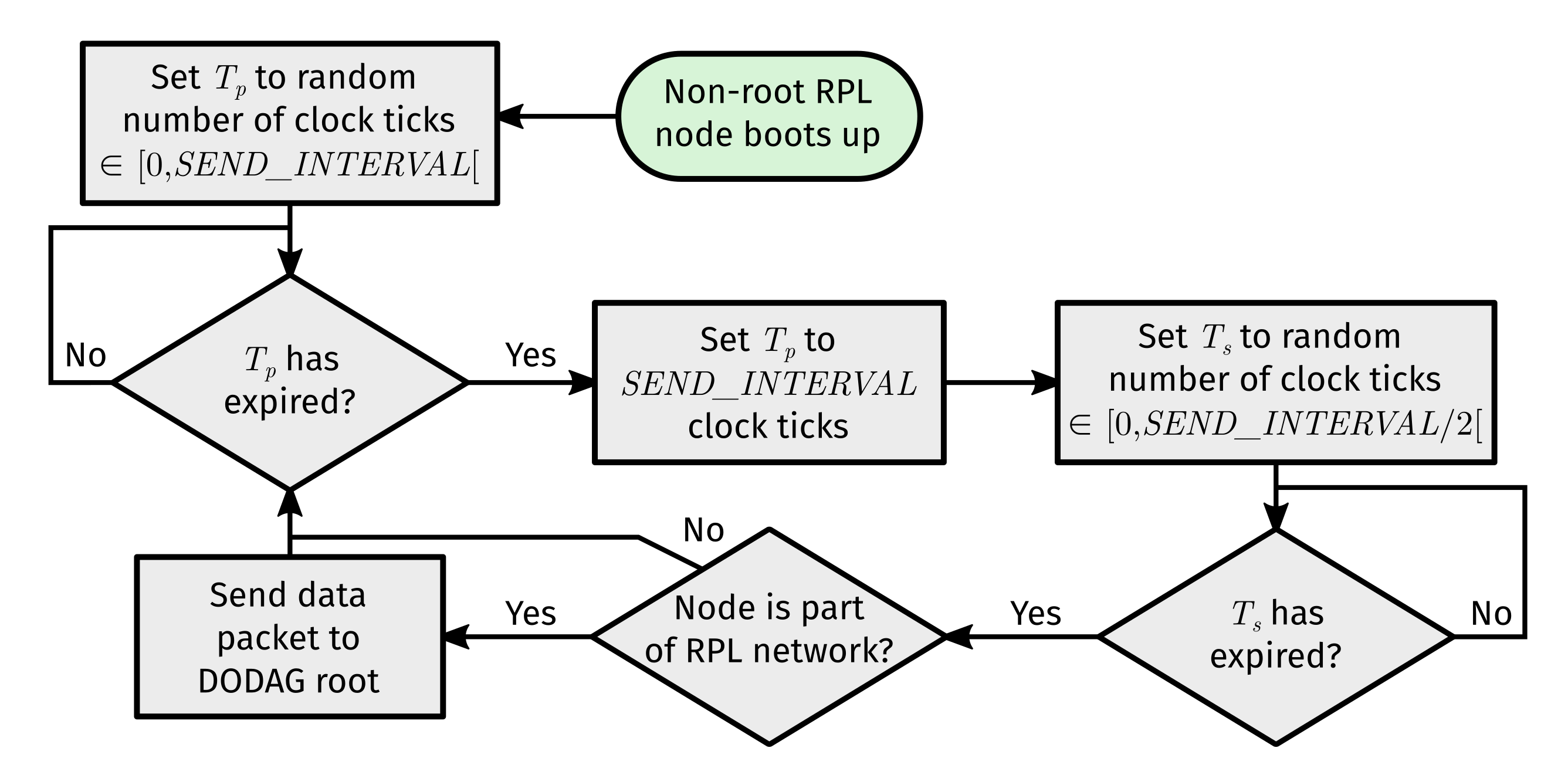
- The per-source Packet Delivery Ratio (PDR) is defined, separately for each non-root node, as the ratio of data packets that were processed by the root’s transport layer to the number of send timer () expiration events. This metric does take into account data packets that: (1) were not sent up the DODAG because a node was detached; or (2) got dropped.
- The time spent as orphan is the time a non-root node spends detached from the DODAG. We start counting from the moment the root starts a DODAG or from the moment the non-root node booted if it did so after DODAG creation.
- The per-source number of retransmissions is defined, separately for each non-root node, as the total number of times it had to retransmit unicast packets to any next-hop neighbor because it did not receive a link-layer acknowledgment.
- The per-node transmit energy is defined, separately for each node (including the root), as the energy spent transmitting over the medium. It is calculated from the clock ticks the radios spent in transmit mode (reported to the Contiki-NG Energest module), the operating frequency, and transmit power. Since Energest cannot distinguish between interfaces, we assumed they all operated with the same transmit power (0 dBm).
- The time-weighted average number of hops is defined, separately for each non-root node, as the average number of hops along the path to the root, adjusted for the portion of simulation time for which a given path had said length. A hop is defined as a router along the path to the destination, which is neither the originator nor the endpoint of an IP datagram.
6. Simulation Results and Discussion
6.1. DRiPLOF’s Performance without External Interference
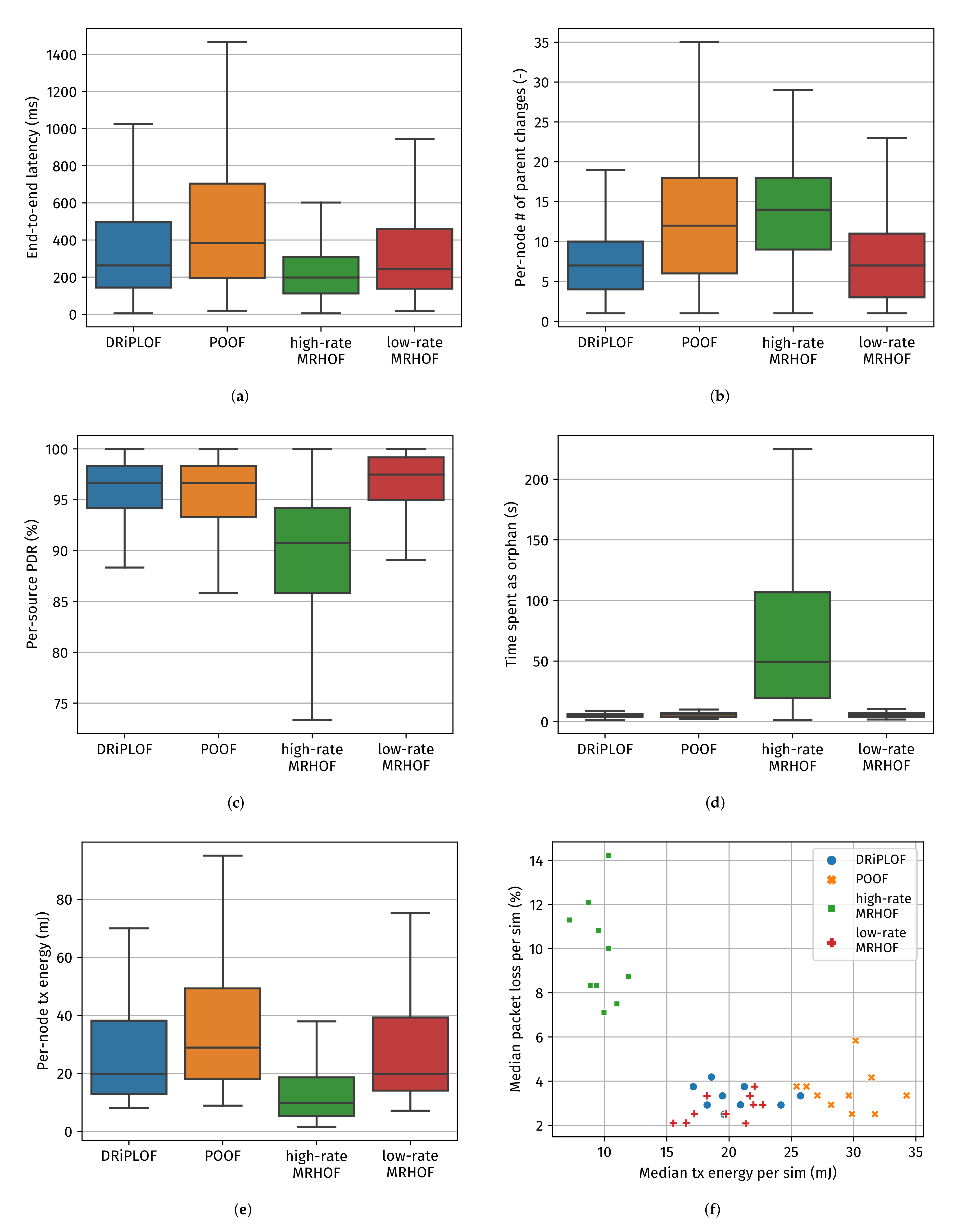
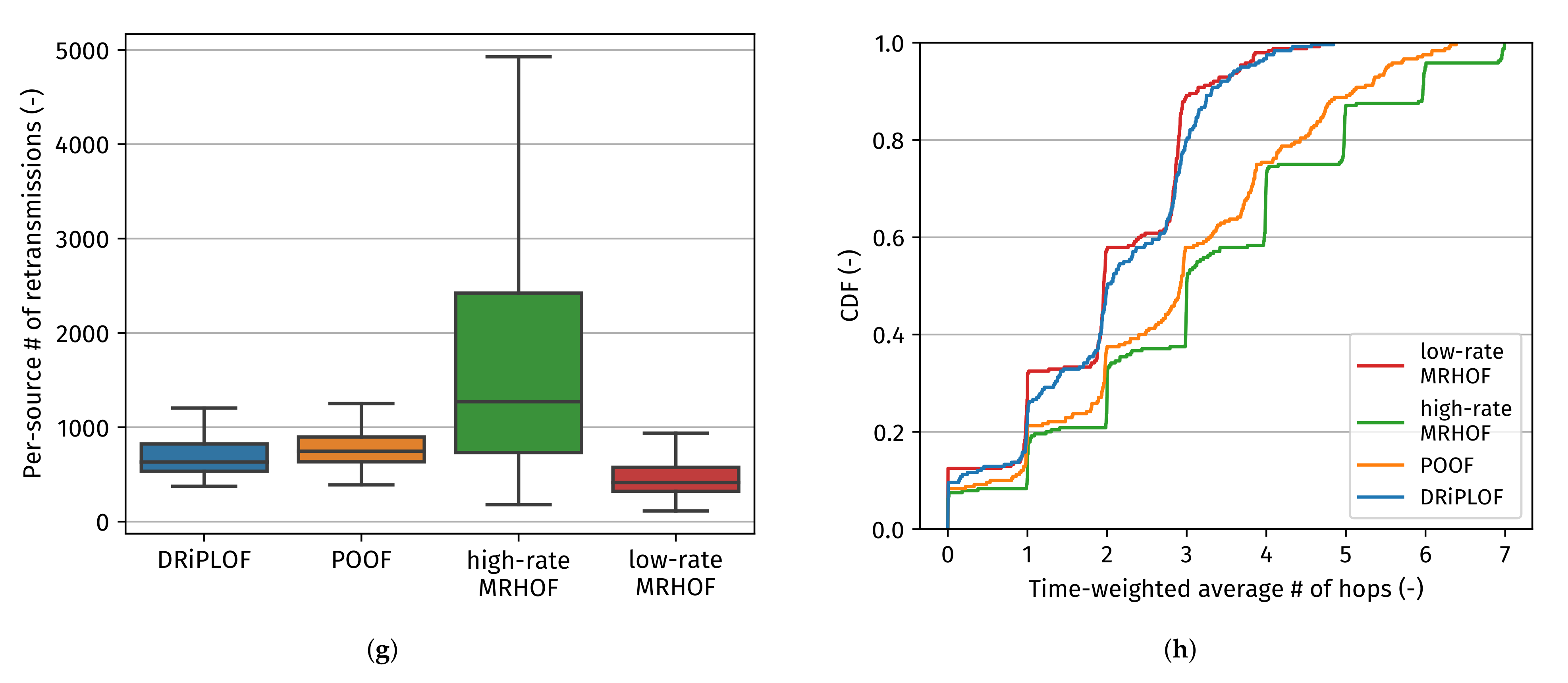
- DRiPLOF exceeds, or otherwise matches, the performance of the state-of-the-art POOF [9,10] in all evaluation metrics. Although the per-source PDR (see Figure 9c) and the number of retransmissions (see Figure 9g) are comparable, DRiPLOF forms a more stable DODAG, as indicated by the number of parent changes (see Figure 9b). This can be explained by the fact that POOF is based on OF0 [16] and, thus, requires an additional stability mechanism, which we found to be inconsistent because it relies on infrequent OF calls (the occurrence of which varies between implementations).
- DRiPLOF outperforms the single-interface approach using MRHOF with high-rate/short-range links (hereafter called “high-rate MRHOF”) in all cases, except for end-to-end latency (Figure 9a) and per-node transmit energy (Figure 9e). While the higher transmit energy cost of DRiPL is partially caused by the additional control traffic required for multi-interface operation, it is mainly because with the high-rate MRHOF, nodes spend more time as orphans (which cannot send data packets to the root and, hence, consume less transmit energy) (Figure 9d). Likewise, the end-to-end latency is artificially kept low, since dropped packets and detached/orphaned nodes are not accounted for (since those cases would equate to infinite latency).
- DRiPLOF matches, or is otherwise close to, the performance of the single-interface approach using MRHOF [11] with low-rate/long-range links (hereafter called “low-rate MRHOF”). Since DRiPLOF is based on MRHOF and because, with DRiPLOF, nodes generally prefer the low-rate interfaces, both solutions form relatively short and stable paths (Figure 9b,h). Although the transmit energy consumption of DRiPLOF is slightly higher due to control traffic duplication over both interfaces, in practice, this effect is negligible compared to the overall energy consumption of the devices. For all practical purposes, DRiPLOF matches the performance of the best single-hop solution we tested (when there is no cross-technology interference).
6.2. DRiPLOF’s Performance in the Face of External Stressors
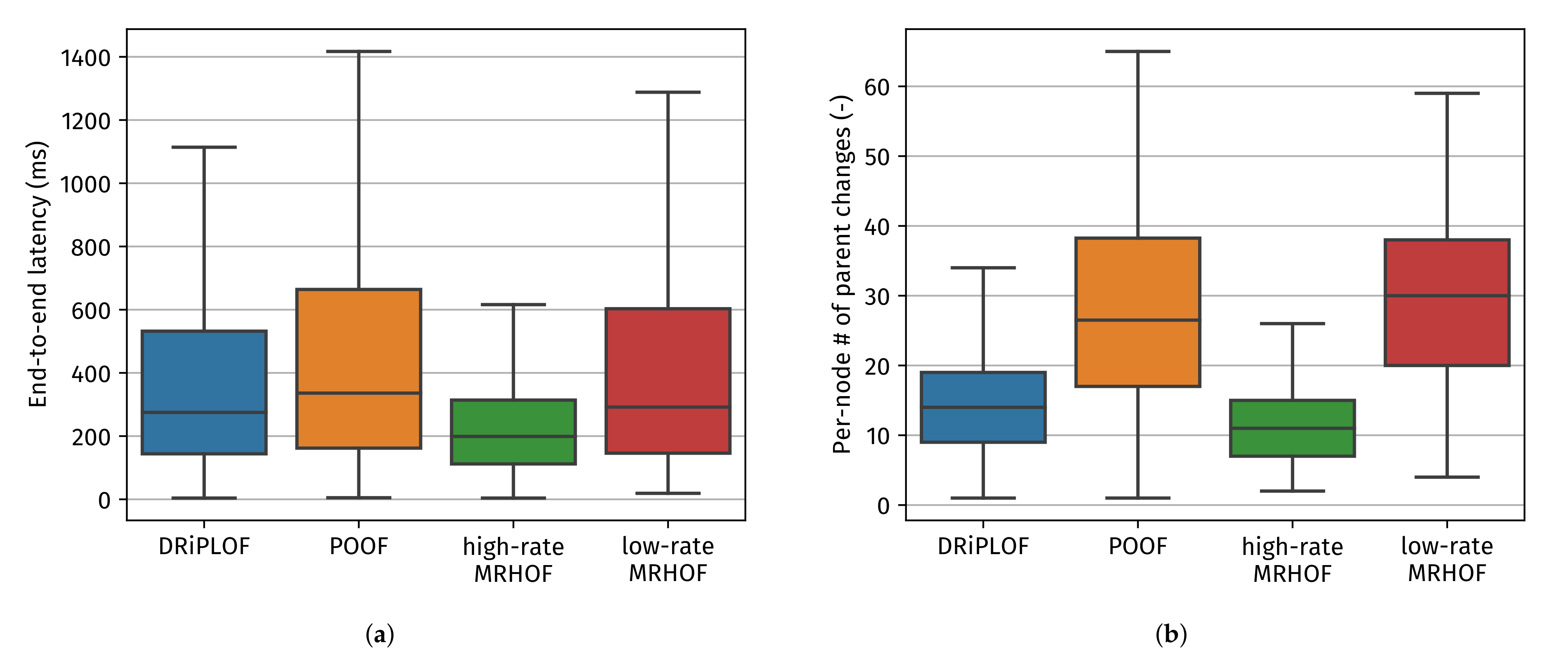
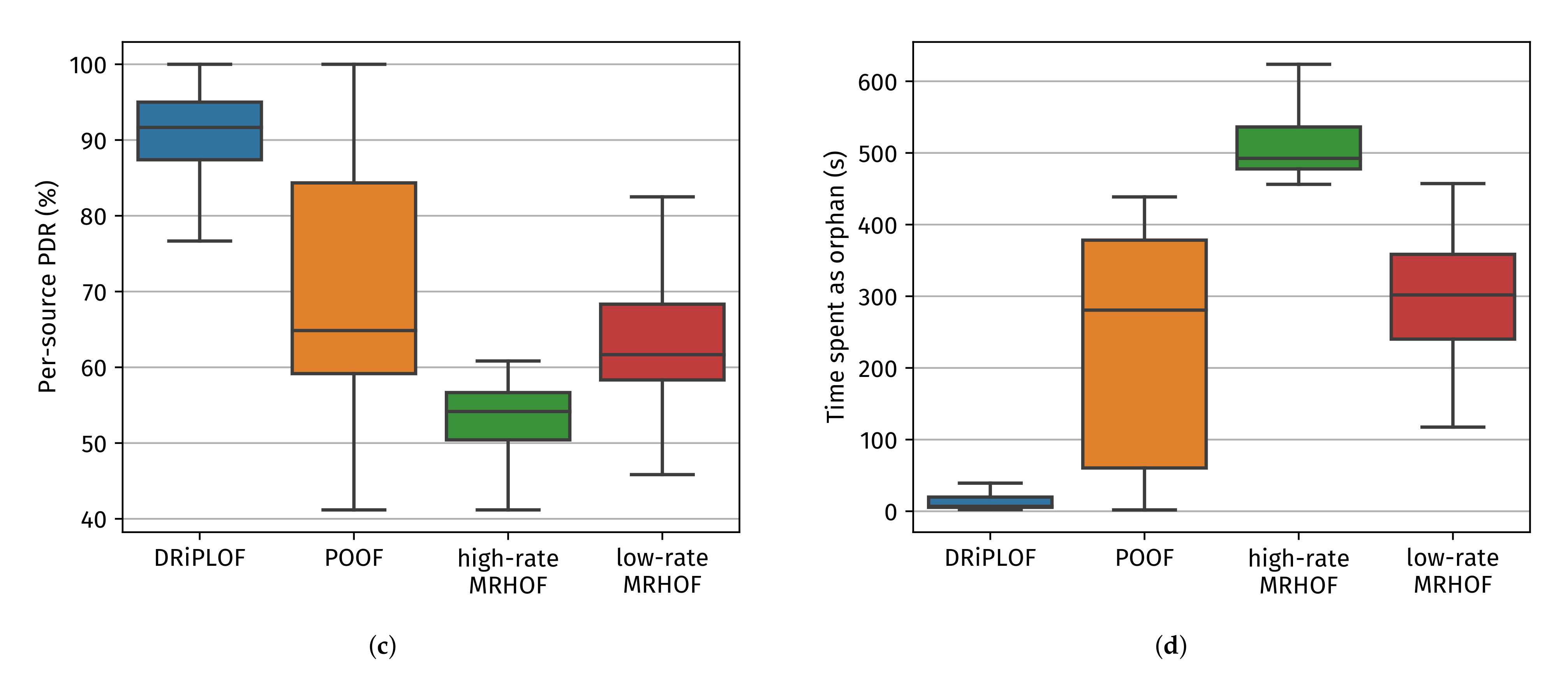
- The improved stability of DRiPLOF over POOF is significant, as shown by the number of parent changes (Note that, similar to end-to-end latency, the per-node number of parent changes may be kept artificially low if nodes are orphaned often. Nonetheless, if the time spent as an orphan is higher for a given solution while that solution also has a higher number of parent changes, that is a bad sign.) (Figure 10b) and time spent as an orphan (Figure 10d). These metrics indicate that DRiPLOF pays a much lower convergence penalty than POOF. That is, although the stability mechanism of POOF already causes more parent changes than DRiPLOF in baseline conditions, the difference is more pronounced here. Moreover, where previously the time spent as an orphan was similar, nodes now spend much more time as an orphan with POOF. This shows that POOF’s lesser stability mechanism is not the only culprit, since that leads to more switching between actual parents, not to nodes emptying their parent set. This can be explained by the unavailable interface penalty being much more severe for POOF, which increases the chance of having to drop the preferred parent. This is most problematic for nodes close to the root, whom typically have small parent sets because of rank requirements. If those drop their preferred parent, there is a high chance of them needing to perform a local repair. Even worse, these nodes often have large sub-DODAGs, meaning a local repair has great potential for high convergence penalties [5]. To be fair, we could lower POOF’s unavailable interface penalty, however not by such a quantity that its convergence penalty becomes trivial.
- DRiPLOF now outperforms all other OF/interface configurations. Especially noteworthy is the per-source PDR (Figure 10c), which was comparable between DRiPLOF, low-rate MRHOF, and POOF under baseline conditions, but only remained relatively stable for DRiPLOF when jamming was involved. Because we are blocking all possible connections to the root in the single-interface case, there is no point in comparing network stability between DRiPLOF and low-/high-rate MRHOF, since a single-interface solution can really only wait for the jamming to end.
- As mentioned before, end-to-end latency (Figure 10a) is artificially kept low when delivery rates (Figure 10c) are low and/or nodes spend much time being orphaned (Figure 10d). As such, Figure 10a should not be used to compare DRiPLOF with POOF nor low-/high-rate MRHOF, but rather with the end-to-end latency of DRiPLOF in non-jamming circumstances (Figure 9a), as the delivery rate and time spent as an orphan are relatively comparable. Doing so reveals that DRiPLOF’s ability to quickly adapt to changing conditions without incurring a large convergence penalty does not come at the cost of increased end-to-end latency.
7. Conclusions and Future Work
Supplementary Materials
Author Contributions
Funding
Institutional Review Board Statement
Informed Consent Statement
Data Availability Statement
Acknowledgments
Conflicts of Interest
Abbreviations
| 6LoWPAN | IPv6 over Low-Power Wireless Personal Area Network |
| 6TiSCH | IPv6 over the TSCH mode of IEEE 802.15.4e |
| ACK | Acknowledgment |
| CA | Collision Avoidance |
| CSMA | Carrier-Sense Multiple Access |
| DAD | Duplicate Address Detection |
| DAO | Destination Advertisement Object |
| DIO | DODAG Information Object |
| DIS | DODAG Information Solicitation |
| DODAG | Destination-Oriented Directed Acyclic Graph |
| DODAGID | DODAG Identifier |
| DRiPL | Dual Radio-Interface Routing Protocol for LLNs |
| DRiPLOF | DRiPL Objective Function |
| ETX | Expected number of Transmissions |
| GHz | Gigahertz |
| ICMP | Internet Control Message Protocol |
| ICMPv6 | ICMP Version 6 |
| IEEE | Institute of Electrical and Electronics Engineers |
| IETF | Internet Engineering Task-Force |
| IO | Interface Oriented |
| IP | Internet Protocol |
| IPv6 | IP Version 6 |
| IoT | Internet of Things |
| JNI | Java Native Interface |
| LLN | Low-power and Lossy Network |
| LQL | Link-Quality Level |
| MAC | Medium Access Control |
| MHz | Megahertz |
| MI | Multiple RPL Instances |
| MOP | Mode Of Operation |
| MP2P | Multi-Point to Point |
| MRHOF | Minimum Rank with Hysteresis Objective Function |
| NA | Neighbor Advertisement |
| NCE | Neighbor Cache Entry |
| ND | Neighbor Discovery |
| NS | Neighbor Solicitation |
| NUD | Neighbor Unreachability Detection |
| OCP | Objective Code Point |
| OF | Objective Function |
| OF0 | Objective Function Zero |
| P2MP | Point to Multi-Point |
| PHY | physical layer |
| PIO | Prefix Information Option |
| PLC | Power-Line Communication |
| PO | Parent Oriented |
| QoS | Quality of Service |
| RA | Router Advertisement |
| RPI | RPL Packet Information |
| RPL | Routing Protocol for Low-power and Lossy Networks |
| RS | Router Solicitation |
| TSCH | Time-Slotted Channel Hopping |
| WSN | Wireless Sensor Network |
Appendix A. IPv6 Neighbor Discovery
Appendix B. Contiki-NG Modifications in Detail
- The rank computed for the path through the preferred parent.
- The highest rank advertised by any of its parent set members (≠the computed rank for the path through said node), rounded to the next higher integral rank.
- The largest computed rank through the parent set, minus MaxRankIncrease.
References
- IEEE Std 802.15.4e-2012 (Amendment to IEEE Std 802.15.4-2011); IEEE Standard for Local and Metropolitan Area Networks—Part 15.4: Low-Rate Wireless Personal Area Networks (LR-WPANs) Amendment 1: MAC sublayer. IEEE: Piscataway, NJ, USA, 2012; pp. 1–225.
- Vilajosana, X.; Pister, K.; Watteyne, T. Minimal IPv6 over the TSCH Mode of IEEE 802.15.4e (6TiSCH) Configuration; RFC 8180; IETF: Fremont, CA, USA, 2017; pp. 1–28. [Google Scholar]
- Thubert, P. An Architecture for IPv6 over the Time-Slotted Channel Hopping Mode of IEEE 802.15.4 (6TiSCH); RFC 9030; IETF: Fremont, CA, USA, 2021; pp. 1–57. [Google Scholar]
- Winter, T.; Thubert, P.; Brandt, A.; Hui, J.; Kelsey, R.; Levis, P.; Pister, K.; Struik, R.; Vasseur, J.P.; Alexander, R. RPL: IPv6 Routing Protocol for Low-Power and Lossy Networks; RFC 6550; IETF: Fremont, CA, USA, 2012; pp. 1–157. [Google Scholar]
- Tabaja, A.; Cohen, R. When the Network of a Smart City Is Not So Smart. In Proceedings of the 2020 IEEE Conference on Communications and Network Security (CNS ’20), Avignon, France, 29 June–1 July 2020; pp. 1–9. [Google Scholar]
- Vilajosana, X.; Watteyne, T.; Chang, T.; Vučinić, M.; Duquennoy, S.; Thubert, P. IETF 6TiSCH: A Tutorial. IEEE Commun. Surv. Tutorials 2020, 22, 595–615. [Google Scholar] [CrossRef]
- Shelby, Z.; Chakrabarti, S.; Nordmark, E.; Bormann, C. Neighbor Discovery Optimization for IPv6 over Low-Power Wireless Personal Area Networks (6LoWPANs); RFC 6775; IETF: Fremont, CA, USA, 2012; pp. 1–55. [Google Scholar]
- Thubert, P.; Nordmark, E.; Chakrabarti, S.; Perkins, C. Registration Extensions for IPv6 over Low-Power Wireless Personal Area Network (6LoWPAN) Neighbor Discovery; RFC 8505; IETF: Fremont, CA, USA, 2018; pp. 1–47. [Google Scholar]
- Lemercier, F.; Montavont, N.; Toutain, L.; Vijayasankar, K.; Vedantham, R.; Chiummiento, P. Support for hybrid network in RPL. In Proceedings of the 2016 IEEE International Conference on Smart Grid Communications (SmartGridComm ’16), Sydney, Australia, 6–9 November 2016; pp. 527–532. [Google Scholar]
- Lemercier, F.; Montavont, N. Performance Evaluation of an RPL Hybrid Objective Function for the Smart Grid Network. In Proceedings of the 2018 17th International Conference on Ad-Hoc Networks and Wireless (ADHOC-NOW ’18), Saint-Malo, France, 5–7 September 2018; pp. 27–38. [Google Scholar]
- Gnawali, 0.; Levis, P. The Minimum Rank with Hysteresis Objective Function; RFC 6719; IETF: Fremont, CA, USA, 2012; pp. 1–13. [Google Scholar]
- Contiki-NG: The OS for Next Generation IoT Devices. Available online: https://github.com/contiki-ng/contiki-ng (accessed on 19 January 2022).
- The Cooja Network Simulator. Available online: https://github.com/contiki-ng/cooja (accessed on 26 January 2022).
- Zolertia. Zolertia RE-Mote Platform. Available online: https://github.com/Zolertia/Resources/wiki/RE-Mote (accessed on 26 January 2022).
- Tsvetkov, T. RPL: IPv6 Routing Protocol for Low Power and Lossy Networks. In Proceedings of the Seminar “Sensor Nodes: Operation, Network and Application” (SN ’11), Munich, Germany, July 2011; pp. 59–66. [Google Scholar]
- Vasseur, J.P.; Kim, M.; Pister, K.; Dejean, N.; Barthel, D. Routing Metrics Used for Path Calculation in Low-Power and Lossy Networks; RFC 6551; IETF: Fremont, CA, USA, 2012; pp. 1–30. [Google Scholar]
- Thubert, P. Objective Function Zero for the Routing Protocol for Low-Power and Lossy Networks (RPL); RFC 6552; IETF: Fremont, CA, USA, 2012; pp. 1–14. [Google Scholar]
- Hui, J.; Vasseur, J.P.; Culler, D.; Manral, V. An IPv6 Routing Header for Source Routes with the Routing Protocol for Low-Power and Lossy Networks (RPL); RFC 6554; IETF: Fremont, CA, USA, 2012; pp. 1–13. [Google Scholar]
- Thubert, P.; Bormann, C.; Toutain, L.; Cragie, R. IPv6 over Low-Power Wireless Personal Area Network (6LoWPAN) Routing Header; RFC 8138; IETF: Fremont, CA, USA, 2017; pp. 1–37. [Google Scholar]
- IEEE Std 802.15.4-2020 (Revision of IEEE Std 802.15.4-2015); IEEE Standard for Low-Rate Wireless Networks. IEEE: Piscataway, NJ, USA, 2020; pp. 1–800.
- Jang, Y.; Kim, Y.; Park, S.; Choi, S. Link Adaptation Strategies for IEEE 802.15.4 WPANs: Protocol Design and Performance Evaluation. J. Commun. Netw. 2019, 21, 376–384. [Google Scholar] [CrossRef]
- Boucetta, C.; Nour, B.; Moungla, H.; Lahlou, L. An IoT Scheduling and Interference Mitigation Scheme in TSCH Using Latin Rectangles. In Proceedings of the 2019 IEEE Global Communications Conference (GLOBECOM ’19), Puako, USA, 9–13 December 2019; pp. 1–6. [Google Scholar]
- Krueger, L.; Steenbrink, L.; Timm-Giel, A. Avoiding Local Interference in IEEE 802.15.4 TSCH Networks using a Scheduling Function with Distributed Blacklists. In Proceedings of the Mobile Communication—Technologies and Applications; 24. ITG-Symposium, Osnabrück, Germany,, 15–16 May 2019; pp. 1–6. [Google Scholar]
- Han, D.; Gnawali, O. Performance of RPL Under Wireless Interference. IEEE Commun. Mag. 2013, 51, 137–143. [Google Scholar]
- Zhang, T.; Ji, X.; Xu, W. Jamming-Resilient Backup Nodes Selection for RPL-Based Routing in Smart Grid AMI Networks. Mob. Networks Appl. 2022, 27, 329–342. [Google Scholar] [CrossRef]
- Bezunartea, M.; Wang, C.; Braeken, A.; Steenhaut, K. Multi-radio Solution for Improving Reliability in RPL. In Proceedings of the 2018 IEEE 29th Annual International Symposium on Personal, Indoor and Mobile Radio Communications (PIMRC ’18), Bologna, Italy, 9–12 September 2018; pp. 129–134. [Google Scholar]
- Balmau, O.; Dzung, D.; Karaaǧaç, A.; Nesovic, V.; Paunovic, A.; Pignolet, Y.A.; Tehrani, N.A. Evaluation of RPL for Medium Voltage Power Line Communication. In Proceedings of the 2014 IEEE International Conference on Smart Grid Communications (SmartGridComm ’14), Venice, Italy, 3–6 November 2014; pp. 446–451. [Google Scholar]
- Narten, T.; Nordmark, E.; Simpson, W.; Soliman, H. Neighbor Discovery for IP Version 6 (IPv6); RFC 4861; IETF: Fremont, CA, USA, 2007; pp. 1–97. [Google Scholar]
- Thomson, S.; Narten, T.; Jinmei, T. IPv6 Stateless Address Autoconfiguration; RFC 4862; IETF: Fremont, CA, USA, 2007; pp. 1–30. [Google Scholar]
- Rady, M.; Lampin, Q.; Barthel, D.; Watteyne, T. g6TiSCH: Generalized 6TiSCH for Agile Multi-PHY Wireless Networking. IEEE Access 2021, 9, 84465–84479. [Google Scholar] [CrossRef]
- Van Leemput, D.; Bauwens, J.; Elsas, R.; Hoebeke, J.; Joseph, W.; De Poorter, E. Adaptive multi-PHY IEEE802.15.4 TSCH in sub-GHz industrial wireless networks. Ad Hoc Netw. 2021, 111, 102330. [Google Scholar] [CrossRef]
- Zolertia. The Zoul Module. Available online: https://github.com/Zolertia/Resources/wiki/The-Zoul-module (accessed on 22 February 2022).
- Java Native Interface Specification Contents. Available online: https://docs.oracle.com/javase/8/docs/technotes/guides/jni/spec/jniTOC.html (accessed on 31 January 2022).
- Rappaport, T.S. Wireless Communications, Principles and Practice, 2nd ed.; Prentice-Hall: Upper Saddle River, NJ, USA, 2002; ISBN 0-13-042232-0. [Google Scholar]
- Seidel, Y.S.; Rappaport, T.S. 914 MHz Path Loss Prediction Models for Indoor Wireless Communications in Multifloored Buildings. IEEE Trans. Antennas Propag. 1992, 40, 207–217. [Google Scholar] [CrossRef]
- Kaddouri, S.; Hajj, M.E.; Zaharia, G.; Zein, G.E. Indoor Path Loss Measurements and Modeling in an Open-Space Office at 2.4 GHz and 5.8 GHz in the Presence of People. In Proceedings of the 2018 IEEE 29th Annual International Symposium on Personal, Indoor and Mobile Radio Communications (PIMRC ’18), Bologna, Italy, 9–12 September 2018; pp. 1–7. [Google Scholar]
- Wunderlich, S.; Welpot, M.; Gaspard, I. Indoor radio channel modeling and mitigation of fading effects using linear and circular polarized antennas in combination for smart home system at 868 MHz. Adv. Radio Sci. 2014, 12, 53–59. [Google Scholar] [CrossRef][Green Version]
- Kurt, S.; Tavli, B. Path-Loss Modeling for Wireless Sensor Networks: A review of models and comparative evaluations. IEEE Antennas Propag. Mag. 2017, 1, 18–37. [Google Scholar] [CrossRef]
- IEEE Std 802.11-2020 (Revision of IEEE Std 802.11-2016); IEEE Standard for Information Technology–Telecommunications and Information Exchange between Systems—Local and Metropolitan Area Networks–Specific Requirements—Part 11: Wireless LAN Medium Access Control (MAC) and Physical Layer (PHY) Specifications. IEEE: Piscataway, NJ, USA, 2021; pp. 1–4379.
- LoRaWAN L2 1.0.4 Specification; TS1-1.0.4 (Rev. 1.0.4). LoRa Alliance: Fremont, CA, USA, 2020; pp. 1–90.
- Cam-Winget, N.; Hui, J.; Popa, D. Applicability Statement for the Routing Protocol for Low-Power and Lossy Networks (RPL) in Advanced Metering Infrastructure (AMI) Networks; RFC 8036; IETF: Fremont, CA, USA, 2017; pp. 1–24. [Google Scholar]


| Reference | Solution Name | Single DODAG | Stability Mechanism | 6LoWPAN ND Compatible a | Works in Storing and Non-Storing MOP b | Tested under Jamming | Firmware Available | Interfaces |
|---|---|---|---|---|---|---|---|---|
| [9,10] | MI | ✗ | ✗ | ✓ | ✓ | ✗ | ✗ | 1 × 802.15.4g 1 × PLC |
| PO | ✓ | ± | ✓ | ✓ | ✗ | ✗ | ||
| IO | ✓ | ✗ | ± | ? | ✗ | ✗ | ||
| [26] | — | ✓ | ? | ? | ? | ✗ | ✗ | 1 × 802.15.4 1 × 802.15.4g |
| [27] | — | ✓ | ✓ | ✗ | ± | ✗ | ✗ c | 1 × 802.15.4g 1 × PLC |
| [30] | — | ✓ | ✓ | ± | ± | ✗ | ✓ | 2 × 802.15.4g |
| This paper | DRiPL | ✓ | ✓ | ✓ | ✓ | ✓ | ✓ | 2 × 802.15.4 (any) |
| Constant | Interface #1 | Interface #2 |
|---|---|---|
| f | 2400 MHz | 868 MHz |
| 0 dBm | 0 dBm | |
| S | −100 dBm | −100 dBm |
| a | −92 dBm | −92 dBm |
| 0 dBi | 0 dBi | |
| 0 dBi | 0 dBi | |
| c | m/s | m/s |
| 3.0 | 3.0 | |
| b | 3.0 | 5.0 |
| 1.0 m | 1.0 m | |
| ≈ 99.648 m | ≈ 196.303 m |
| Parameter | Value |
|---|---|
| Simulation duration | 20 min/run |
| Simulation runs | 10 runs/config (80 total) |
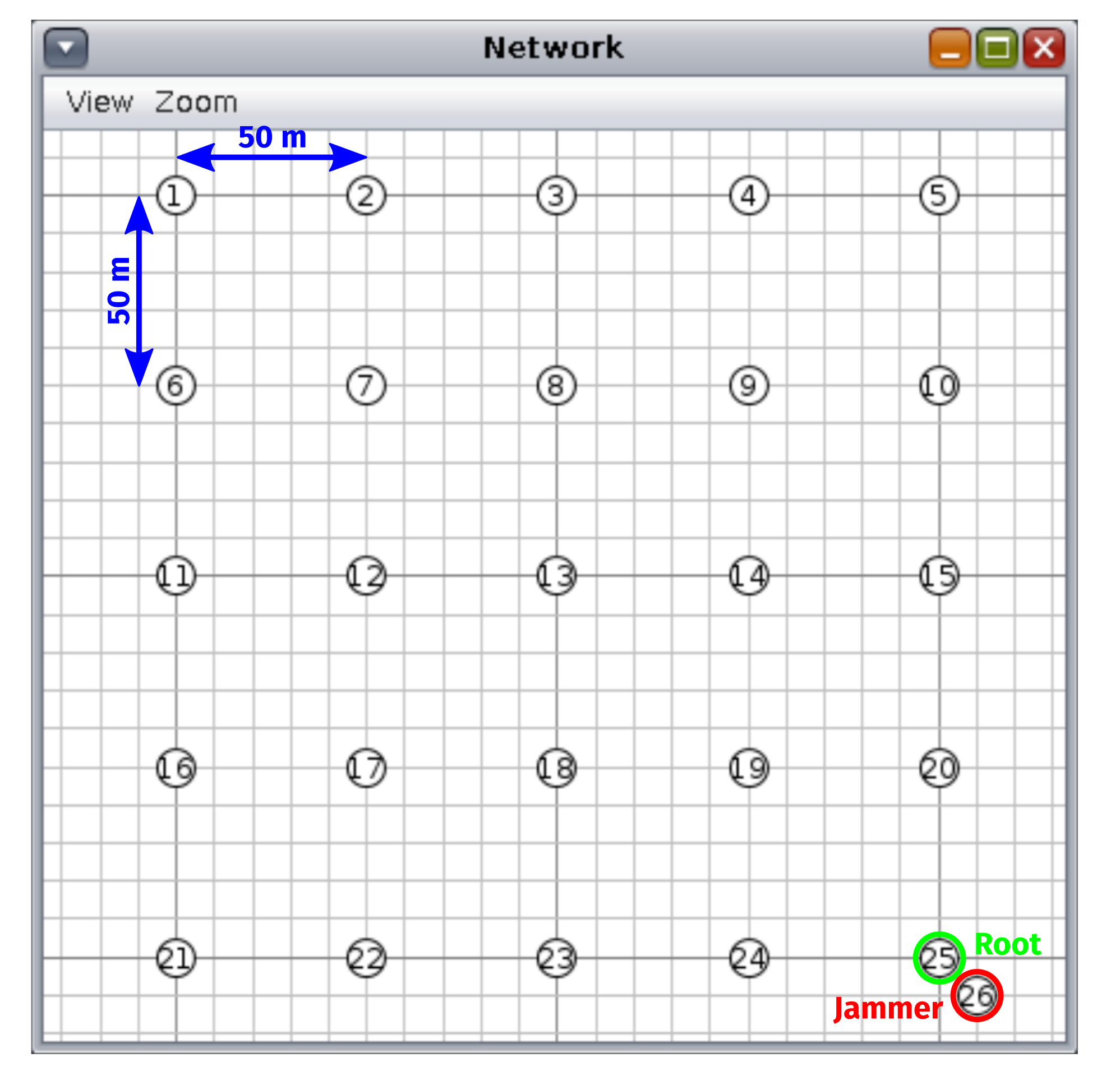
| Grid size | 5 nodes × 5 nodes |
| Inter-node spacing | 50 m |
| Data packet rate | ≈6 packets/min |
| MAC protocol | CSMA-CA (always-on) |
| Data rate | low-rate: 25 kbps |
| high-rate: 250 kbps |
Publisher’s Note: MDPI stays neutral with regard to jurisdictional claims in published maps and institutional affiliations. |
© 2022 by the authors. Licensee MDPI, Basel, Switzerland. This article is an open access article distributed under the terms and conditions of the Creative Commons Attribution (CC BY) license (https://creativecommons.org/licenses/by/4.0/).
Share and Cite
Elsas, R.; De Poorter, E.; Hoebeke, J. DRiPLOF: An RPL Extension for Multi-Interface Wireless Sensor Networks in Interference-Prone Environments. Sensors 2022, 22, 3906. https://doi.org/10.3390/s22103906
Elsas R, De Poorter E, Hoebeke J. DRiPLOF: An RPL Extension for Multi-Interface Wireless Sensor Networks in Interference-Prone Environments. Sensors. 2022; 22(10):3906. https://doi.org/10.3390/s22103906
Chicago/Turabian StyleElsas, Robbe, Eli De Poorter, and Jeroen Hoebeke. 2022. "DRiPLOF: An RPL Extension for Multi-Interface Wireless Sensor Networks in Interference-Prone Environments" Sensors 22, no. 10: 3906. https://doi.org/10.3390/s22103906
APA StyleElsas, R., De Poorter, E., & Hoebeke, J. (2022). DRiPLOF: An RPL Extension for Multi-Interface Wireless Sensor Networks in Interference-Prone Environments. Sensors, 22(10), 3906. https://doi.org/10.3390/s22103906