
Brain Implantable End-Fire Antenna with Enhanced Gain and Bandwidth


Abstract
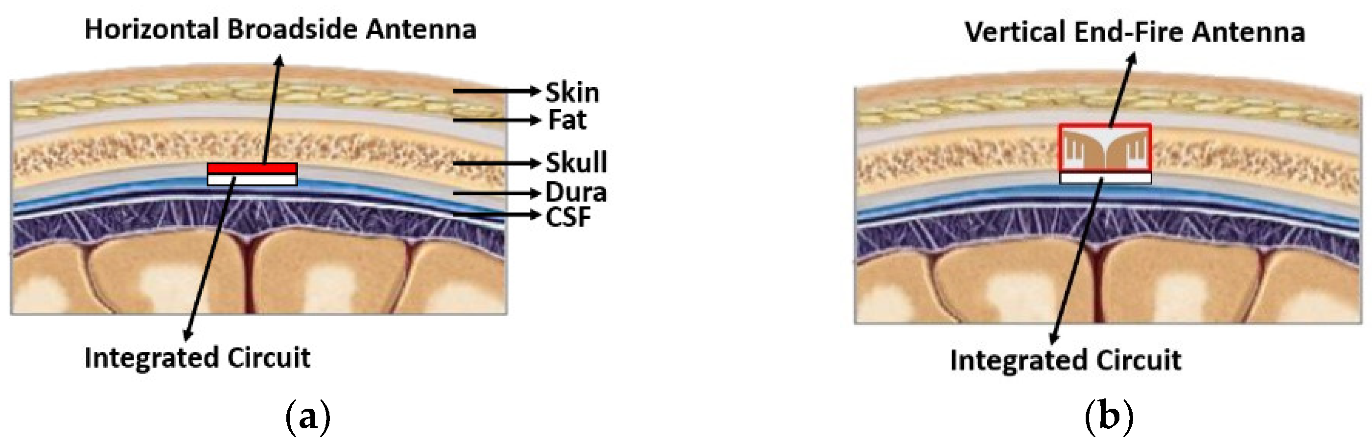
:1. Introduction
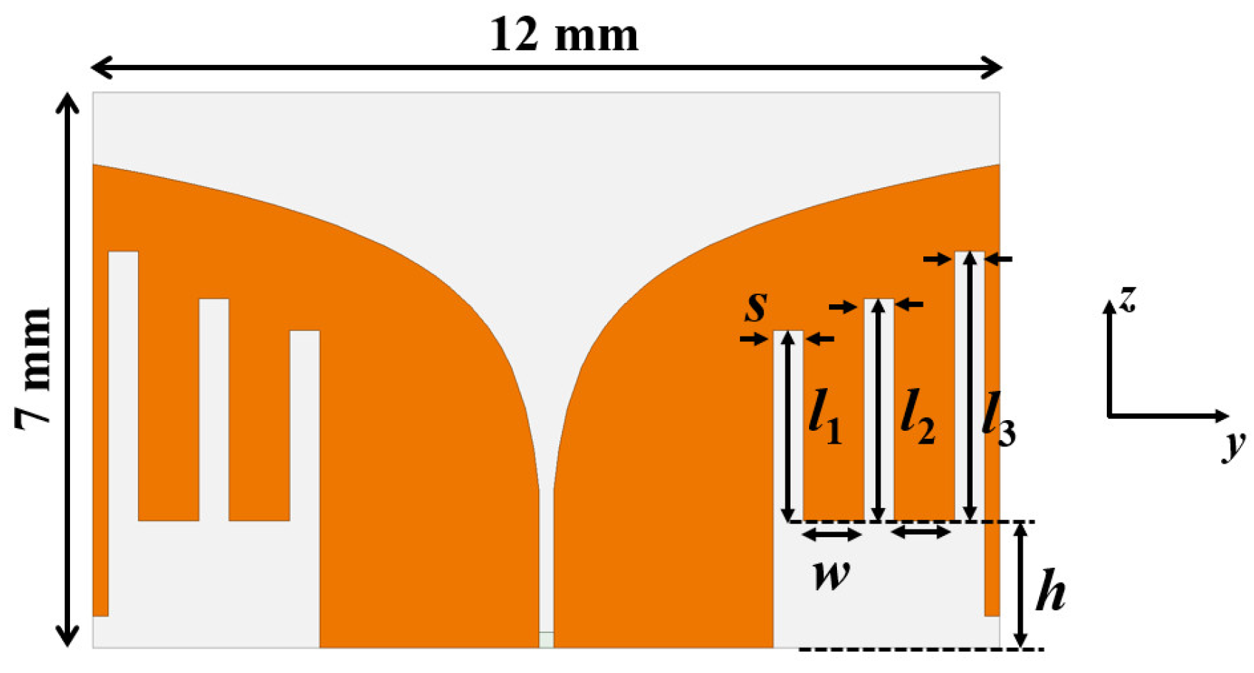
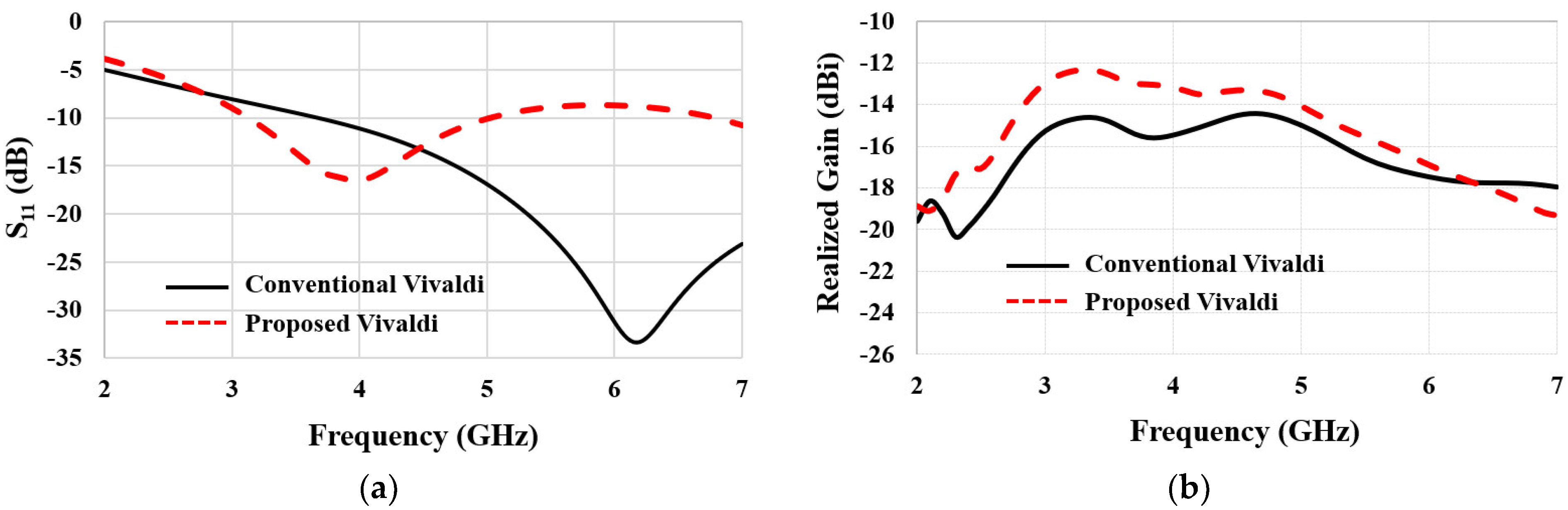
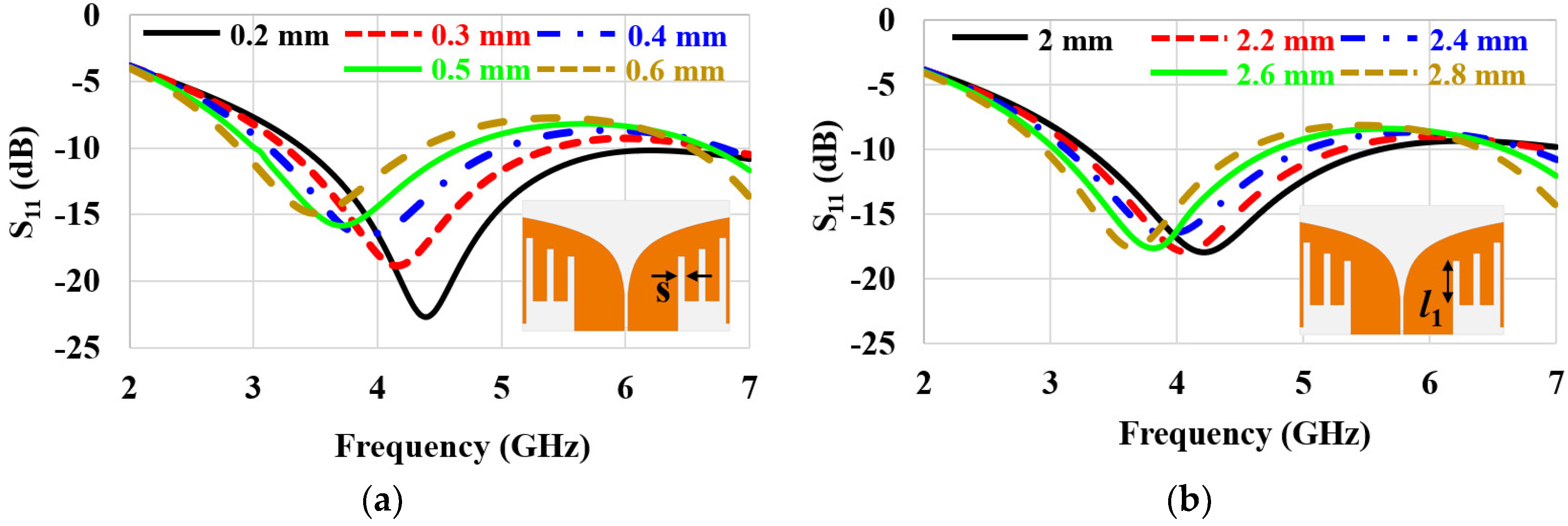
2. Antenna Design
3. Antenna Prototype Fabrication and Measurement
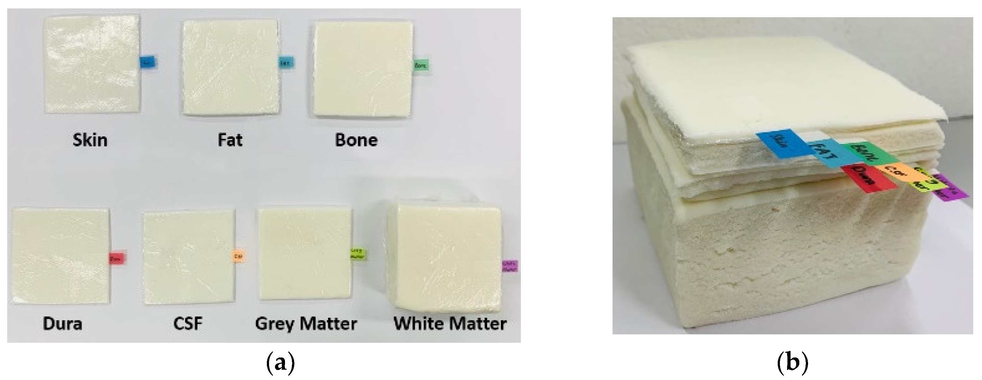
3.1. Fabrication of Brain-Tissue-Emulating Phantom
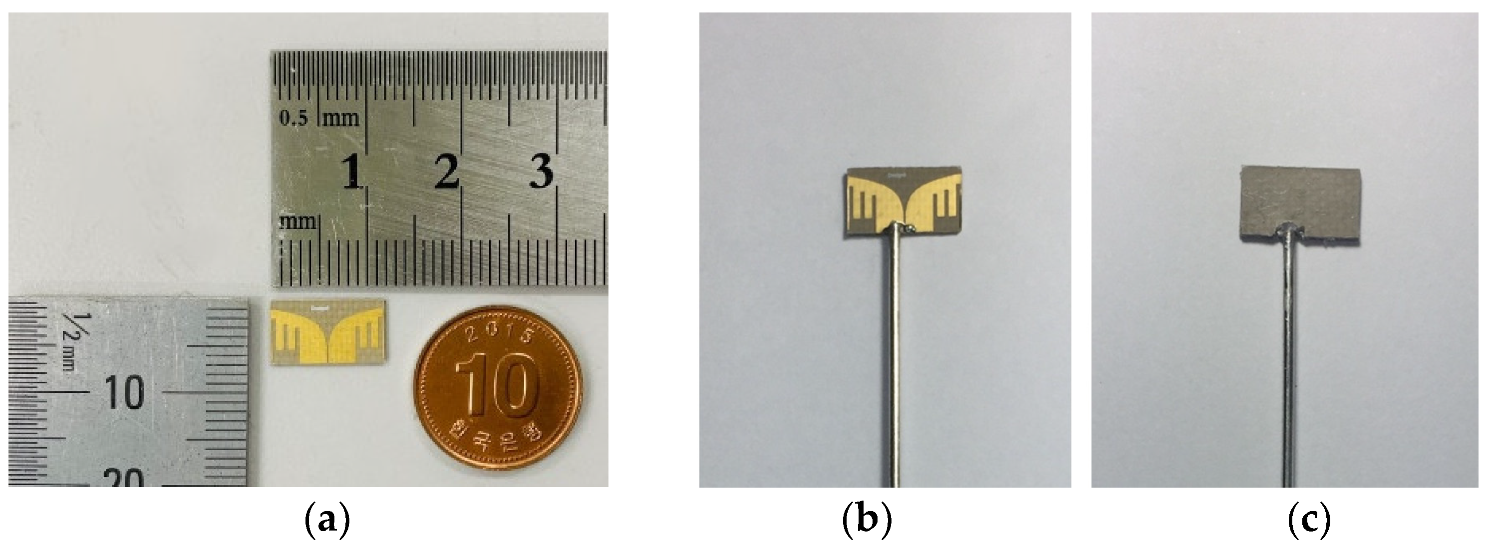
3.2. Fabrication of Antenna Prototype
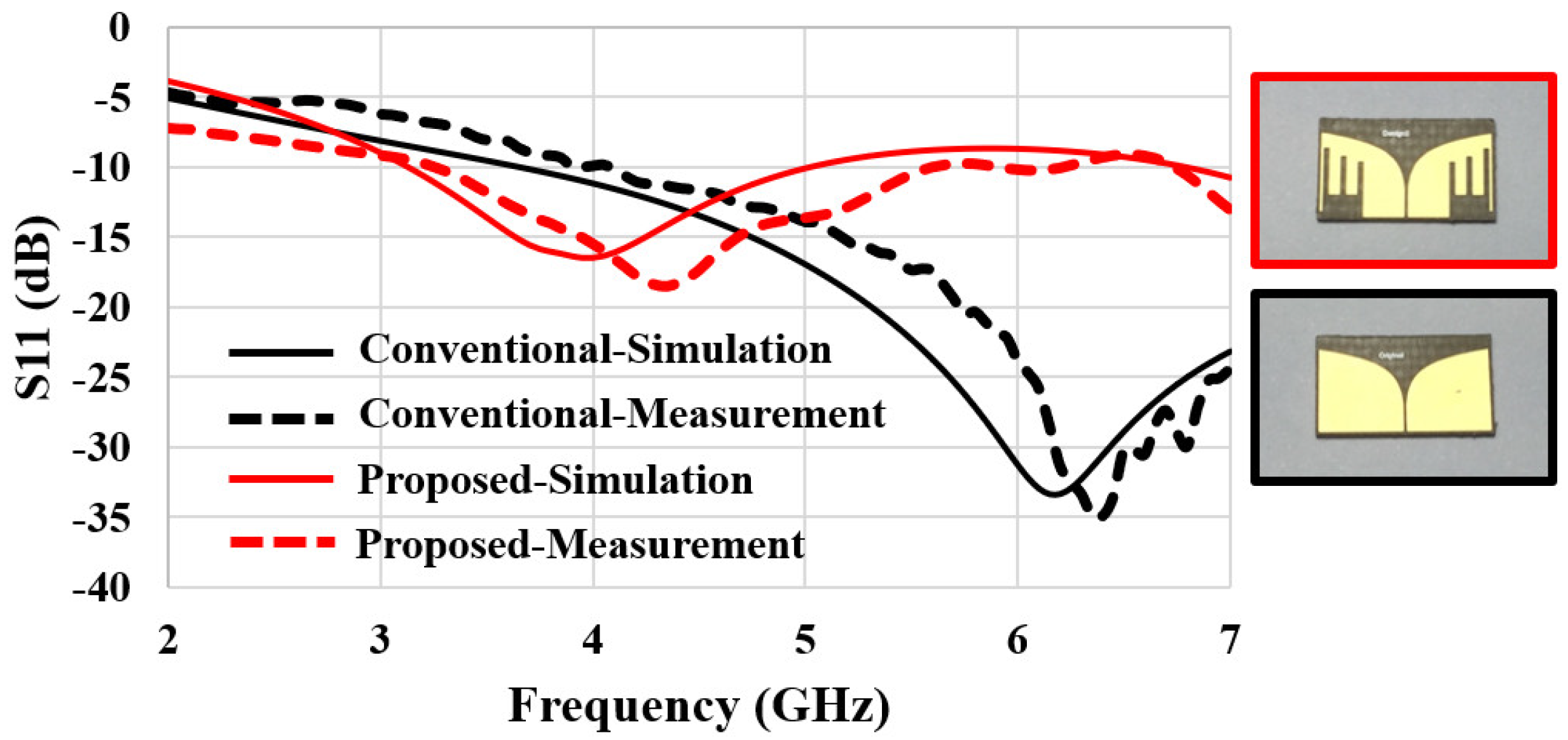
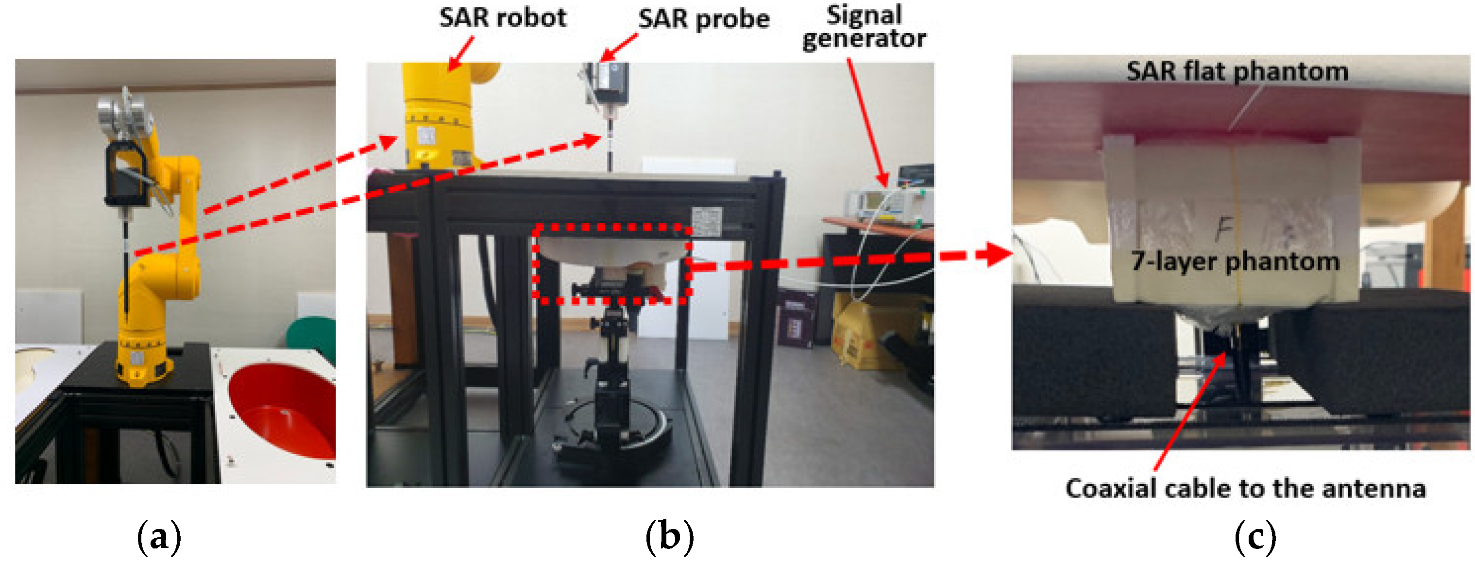
3.3. Measurement of S11
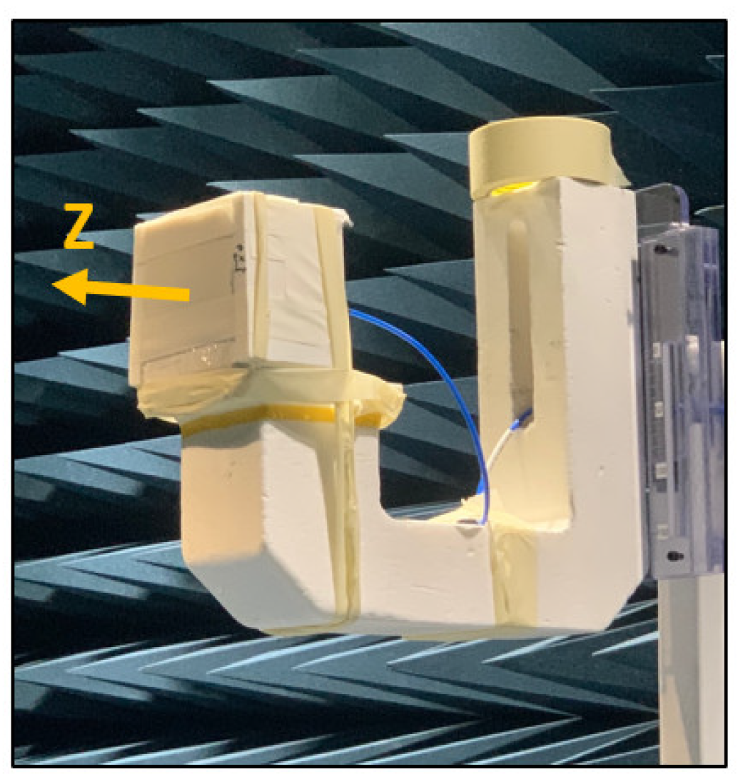
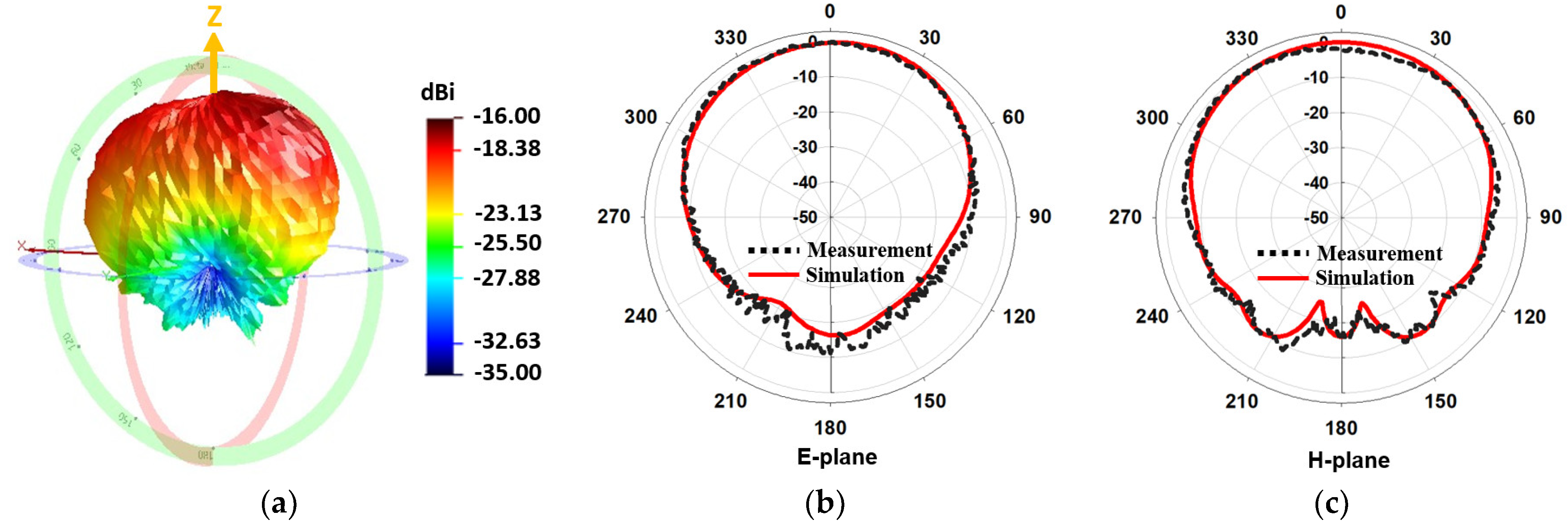
3.4. Measurement of Radiation Pattern
4. Specific Absorption Rate and Link Budget Analysis
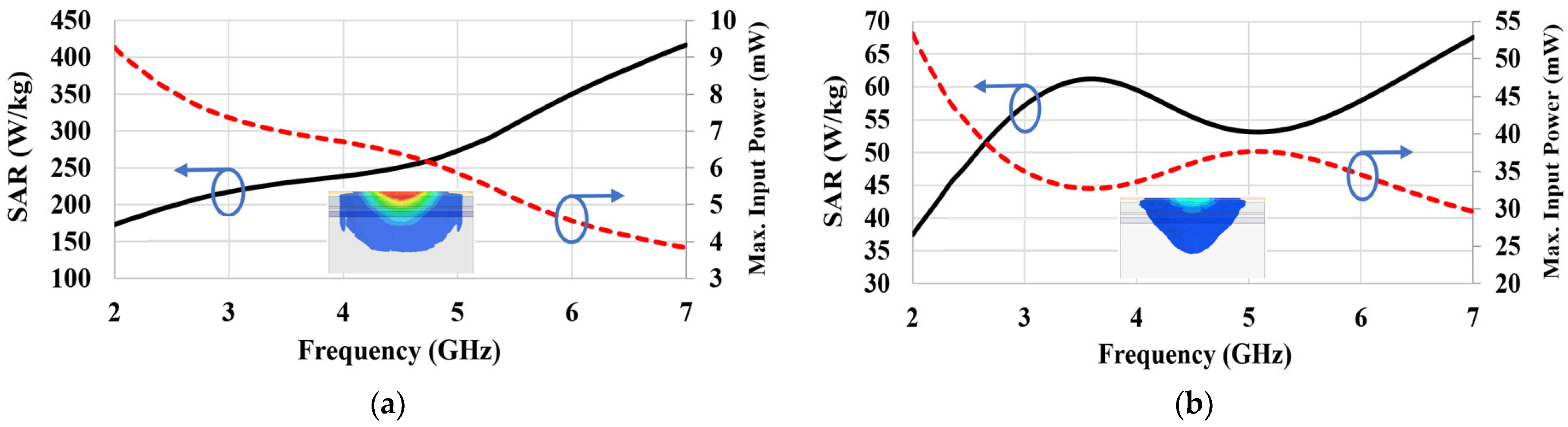
4.1. Specific Absorption Rate
4.2. Link Budget Analysis
5. Conclusions
Author Contributions
Funding
Institutional Review Board Statement
Informed Consent Statement
Data Availability Statement
Conflicts of Interest
References
- Becedas, J. Brain–Machine Interfaces: Basis and Advances. IEEE Trans. Syst. Man Cybern. Part C (Appl. Rev.) 2012, 42, 825–836. [Google Scholar] [CrossRef]
- Mudgal, S.; Sharma, S.; Chaturvedi, J.; Sharma, A. Brain computer interface advancement in neurosciences: Applications and issues. Interdiscip. Neurosurg. 2020, 20, 100694. [Google Scholar] [CrossRef]
- Butt, A.; Alsaffar, H.; Alshareef, M.; Qureshi, K. AI Prediction of Brain Signals for Human Gait Using BCI Device and FBG Based Sensorial Platform for Plantar Pressure Measurements. Sensors 2022, 22, 3085. [Google Scholar] [CrossRef]
- Schalk, G.; Leuthardt, E.C. Brain-Computer Interfaces Using Electrocorticographic Signals. IEEE Rev. Biomed. Eng. 2011, 4, 140–154. [Google Scholar] [CrossRef]
- Ma, S.; Björninen, T.; Sydänheimo, L.; Voutilainen, M.H.; Ukkonen, L. Double Split Rings as Extremely Small and Tuneable Antennas for Brain Implantable Wireless Medical Microsystems. IEEE Trans. Antennas Propag. 2021, 69, 760–768. [Google Scholar] [CrossRef]
- Chen, W.-C.; Lee, C.W.L.; Kiourti, A.; Volakis, J.L. A Multi-Channel Passive Brain Implant for Wireless Neuropotential Monitoring. IEEE J. Electromagn. RF Microw. Med. Biol. 2018, 2, 262–269. [Google Scholar] [CrossRef]
- Lee, C.W.L.; Kiourti, A.; Chae, J.; Volakis, J.L. A High-Sensitivity Fully Passive Neurosensing System for Wireless Brain Signal Monitoring. IEEE Trans. Microw. Theory Tech. 2015, 63, 2060–2068. [Google Scholar] [CrossRef]
- Song, L.; Rahmat-Samii, Y. An End-to-End Implanted Brain–Machine Interface Antenna System Performance Characterizations and Development. IEEE Trans. Antennas Propag. 2017, 65, 3399–3408. [Google Scholar] [CrossRef]
- Blauert, J.; Kang, Y.-S.; Kiourti, A. In Vivo Testing of a Miniature 2.4/4.8 GHz Implantable Antenna in Postmortem Human Subject. IEEE Antennas Wirel. Propag. Lett. 2018, 17, 2334–2338. [Google Scholar] [CrossRef]
- Neuralink approach interfacing with the brain, Neuralink. 2021. Available online: https://neuralink.com (accessed on 1 January 2022).
- Hout, S.; Chung, J.-Y. Design and Characterization of a Miniaturized Implantable Antenna in a Seven-Layer Brain Phantom. IEEE Access 2019, 7, 162062–162069. [Google Scholar] [CrossRef]
- Biswarup, R.; Shim, J.-Y.; Chung, J.-Y. An Implantable Antenna With Broadside Radiation for a Brain–Machine Interface. IEEE Sens. J. 2019, 19, 9200–9205. [Google Scholar]
- Lee, C.W.L.; Kiourti, A.; Volakis, J.L. Miniaturized Fully Passive Brain Implant for Wireless Neuropotential Acquisition. IEEE Antennas Wirel. Propag. Lett. 2016, 16, 645–648. [Google Scholar] [CrossRef]
- Yang, Z.-J.; Zhu, L.; Xiao, S. An Implantable Wideband Microstrip Patch Antenna Based on High-Loss Property of Human Tissue. IEEE Access 2020, 8, 93048–930572020. [Google Scholar] [CrossRef]
- Liapatis, O.; Nikita, K.S. Development of a biocompatible patch antenna for retinal prosthesis: Comparison of biocompatible coatings. In Proceedings of the IEEE 20th International Conference on Bioinformatics and Bioengineering (BIBE), Cincinnati, OH, USA, 26–28 October 2020; pp. 819–825. [Google Scholar]
- Bahrami, H.; Mirbozorgi, S.A.; Nguyen, A.T.; Gosselin, B.; Rusch, L.A. System-Level Design of a Full-Duplex Wireless Transceiver for Brain–Machine Interfaces. IEEE Trans. Microw. Theory Tech. 2016, 64, 3332–3341. [Google Scholar] [CrossRef] [Green Version]
- Lim, H.; Lee, D.-H.; Kim, J.; Hong, S. Spectroscopic Sensing Method of Liquid Permittivity with On-Chip Capacitor. J. Electromagn. Eng. Sci. 2022, 22, 28–33. [Google Scholar] [CrossRef]
- Mahmood, H.U.; Utomo, D.R.; Kim, J.; Lee, S.-G. A 27 dB Sidelobe Suppression, 1.12 GHz BW−10dB UWB Pulse Generator With Process Compensation. IEEE Trans. Circuits Syst. II Express Briefs 2021, 68, 2805–2809. [Google Scholar] [CrossRef]
- Schaubert, D.; Kollberg, E.; Korzeniowski, T.; Thungren, T.; Johansson, J.; Yngvesson, K. Endfire tapered slot antennas on dielectric substrates. IEEE Trans. Antennas Propag. 1985, 33, 1392–1400. [Google Scholar] [CrossRef]
- Gabriel, S.; Lau, R.; Gabriel, C. The dielectric properties of biological tissues: II. Measurements in the frequency range 10 Hz to 20 GHz. Phys. Med. Biol. 1996, 41, 2251–2269. [Google Scholar] [CrossRef] [Green Version]
- Fei, P.; Jiao, Y.-C.; Hu, W.; Zhang, F.-S. A Miniaturized Antipodal Vivaldi Antenna With Improved Radiation Characteristics. IEEE Antennas Wirel. Propag. Lett. 2011, 10, 127–130. [Google Scholar]
- Teni, G.; Zhang, N.; Qiu, J.; Zhang, P. Research on a Novel Miniaturized Antipodal Vivaldi Antenna With Improved Radiation. IEEE Antennas Wirel. Propag. Lett. 2013, 12, 417–420. [Google Scholar] [CrossRef]
- Kim, J. Configuration of a Monopulse Antenna Assembly for Small Diameter Flight Vehicle Applications. J. Electromagn. Eng. Sci. 2021, 21, 246–248. [Google Scholar] [CrossRef]
- Nassar, I.T.; Weller, T.M. A Novel Method for Improving Antipodal Vivaldi Antenna Performance. IEEE Trans. Antennas Propag. 2015, 63, 3321–3324. [Google Scholar] [CrossRef]
- YEl-Saboni; Magil, M.K.; Conway, G.A.; Cotton, S.L.; Scanlon, W.G. Measurement of Deep Tissue Implanted Antenna Efficiency Using a Reverberation Chamber. IEEE J. Electromagn. RF Microw. Med. Biol. 2017, 1, 90–97. [Google Scholar] [CrossRef] [Green Version]
- Felício, J.M.; Fernandes, C.A.; Costa, J.R. Wideband Implantable Antenna for Body-Area High Data Rate Impulse Radio Communication. IEEE Trans. Antennas Propag. 2016, 64, 1932–1940. [Google Scholar] [CrossRef]
- Shim, J.-Y.; Chung, J.-Y. Complex Permittivity Measurement of Artificial Tissue Emulating Material Using Open-Ended Coaxial Probe. IEEE Sens. J. 2020, 20, 4688–4693. [Google Scholar] [CrossRef]
- Electromagnetic Wave Technology Institute. Available online: https://emti.or.kr (accessed on 1 January 2022).
- IEEE Std C95.1, 1999 Edition; IEEE Standard for Safety Levels with Respect to Human Exposure to Radio Frequency Electromagnetic Fields, 3 kHz to 300 GHz. IEEE: New York, NY, USA, 1999; pp. 1–83.
- IEEE Std C95.1-2005; IEEE Standard for Safety Levels with Respect to Human Exposure to Radio Frequency Electromagnetic Fields, 3 kHz to 300 GHz. Revision of IEEE Std C95.1-1991; IEEE: New York, NY, USA, 2006; pp. 1–238.
- Duan, Z.; Guo, Y.-X.; Je, M.; Kwong, D.-L. Design and in Vitro Test of a Differentially Fed Dual-Band Implantable Antenna Operating at MICS and ISM Bands. IEEE Trans. Antennas Propag. 2014, 62, 2430–2439. [Google Scholar] [CrossRef]
- KES Co., Ltd. Available online: http://www.kes.co.kr/ (accessed on 1 January 2022).
- Pozar, D.M. Introduction to Microwave Systems. In Microwave Engineering, 4th Ed; John Wiley & Sons: Hoboken, NJ, USA, 2011; Chapter 4; pp. 671–676. [Google Scholar]
- Bahrami, H.; Mirbozorgi, S.A.; Rusch, L.A.; Gosselin, B. Biological Channel Modeling and Implantable UWB Antenna Design for Neural Recording Systems. IEEE Trans. Biomed. Eng. 2015, 62, 88–98. [Google Scholar] [CrossRef]
- Jeon, G.-H.; Dzagbletey, P.A.; Chung, Y.J. A Cross-Joint Vivaldi Antenna Pair for Dual-Pol and Broadband Testing Capabilities. J. Electromagn. Eng. Sci. 2021, 21, 201–209. [Google Scholar] [CrossRef]


| Layer | Relative Permittivity (εr) | Loss Tangent (tanδ) | Thickness (mm) |
|---|---|---|---|
| Skin | 40.84 | 0.297 | 1 |
| Fat | 5.12 | 0.160 | 2 |
| Skull | 10.53 | 0.310 | 7 |
| Dura | 40.10 | 0.308 | 1.5 |
| CSF | 63.73 | 0.366 | 2 |
| Parameter | Length (mm) |
|---|---|
| s | 0.4 |
| w | 0.8 |
| h | 1.6 |
| l1 | 2.4 |
| l2 | 2.8 |
| l3 | 3.4 |
| Antenna | Frequency (GHz) | Size (mm3) | Gain (dBi) |
|---|---|---|---|
| [11] | 2.40–2.48 | 39.9 | −20.75 |
| [12] | 2.42–2.50 | 50 | −25 |
| [14] | 2.40–2.48 | 101.6 | −17.3 |
| Conventional Vivaldi | 3–5 | 42 | −18.3 |
| Proposed Vivaldi | 3–5 | 42 | −15.7 |
| Parameters | Values at 4 GHz |
|---|---|
| Link margin (LM) | 20 dB |
| Transmit power (Pt) | −25 dBm |
| Tx Ant. realized gain (RGt) | −16.67 dB |
| Rx Ant. realized gain (RGr) | 6.65 dB |
| SNR per bit (Eb/N0) | 9.6 dB |
| Boltzmann’s constant (K) | 1.38 × 10⁻²³ |
| Temperature (T0) | 298 K |
| Bit rate (B) | 256 Mbps |
| Path Loss (L0) |
Publisher’s Note: MDPI stays neutral with regard to jurisdictional claims in published maps and institutional affiliations. |
© 2022 by the authors. Licensee MDPI, Basel, Switzerland. This article is an open access article distributed under the terms and conditions of the Creative Commons Attribution (CC BY) license (https://creativecommons.org/licenses/by/4.0/).
Share and Cite
Sapari, L.; Hout, S.; Chung, J.-Y. Brain Implantable End-Fire Antenna with Enhanced Gain and Bandwidth. Sensors 2022, 22, 4328. https://doi.org/10.3390/s22124328
Sapari L, Hout S, Chung J-Y. Brain Implantable End-Fire Antenna with Enhanced Gain and Bandwidth. Sensors. 2022; 22(12):4328. https://doi.org/10.3390/s22124328
Chicago/Turabian StyleSapari, Lisa, Samnang Hout, and Jae-Young Chung. 2022. "Brain Implantable End-Fire Antenna with Enhanced Gain and Bandwidth" Sensors 22, no. 12: 4328. https://doi.org/10.3390/s22124328
APA StyleSapari, L., Hout, S., & Chung, J.-Y. (2022). Brain Implantable End-Fire Antenna with Enhanced Gain and Bandwidth. Sensors, 22(12), 4328. https://doi.org/10.3390/s22124328