Towards Tomography-Based Real-Time Control of Multiphase Flows: A Proof of Concept in Inline Fluid Separation
Abstract
:1. Introduction
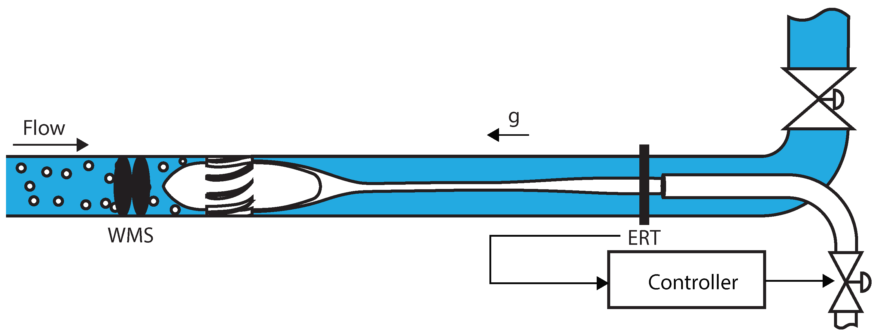
2. A Tomography-Controlled Inline Swirl Separator
3. Experimental Setup
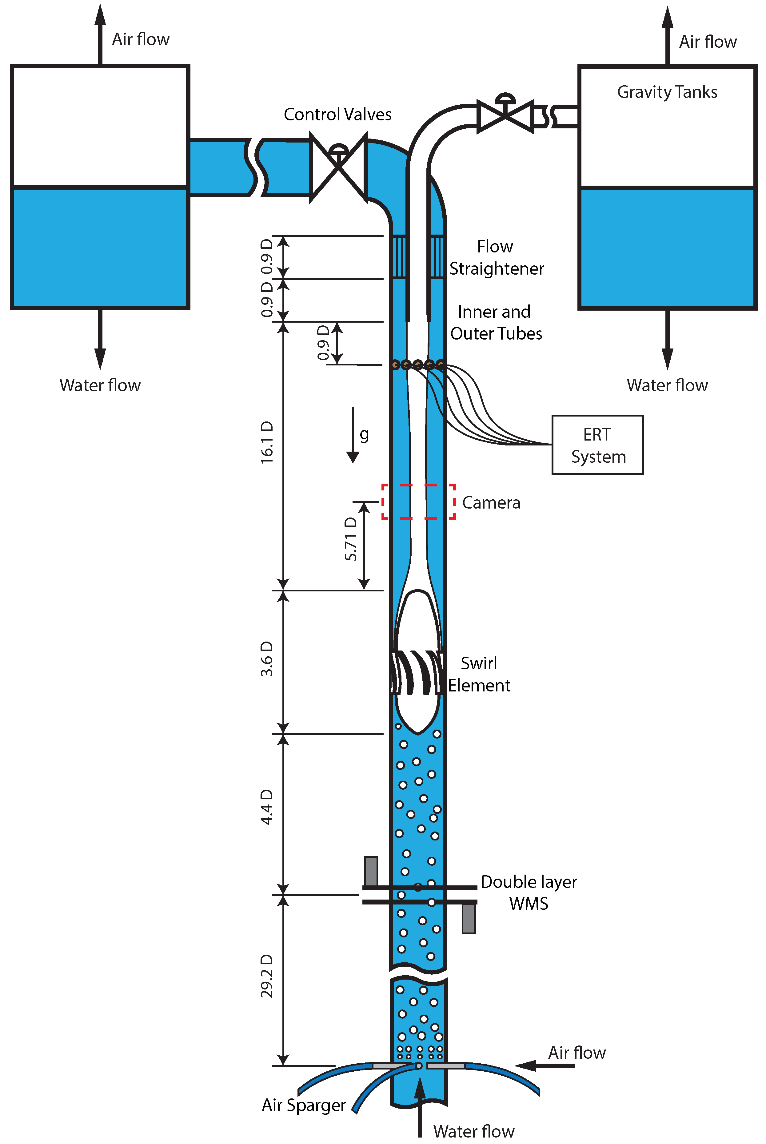
3.1. Flow Loop Facility
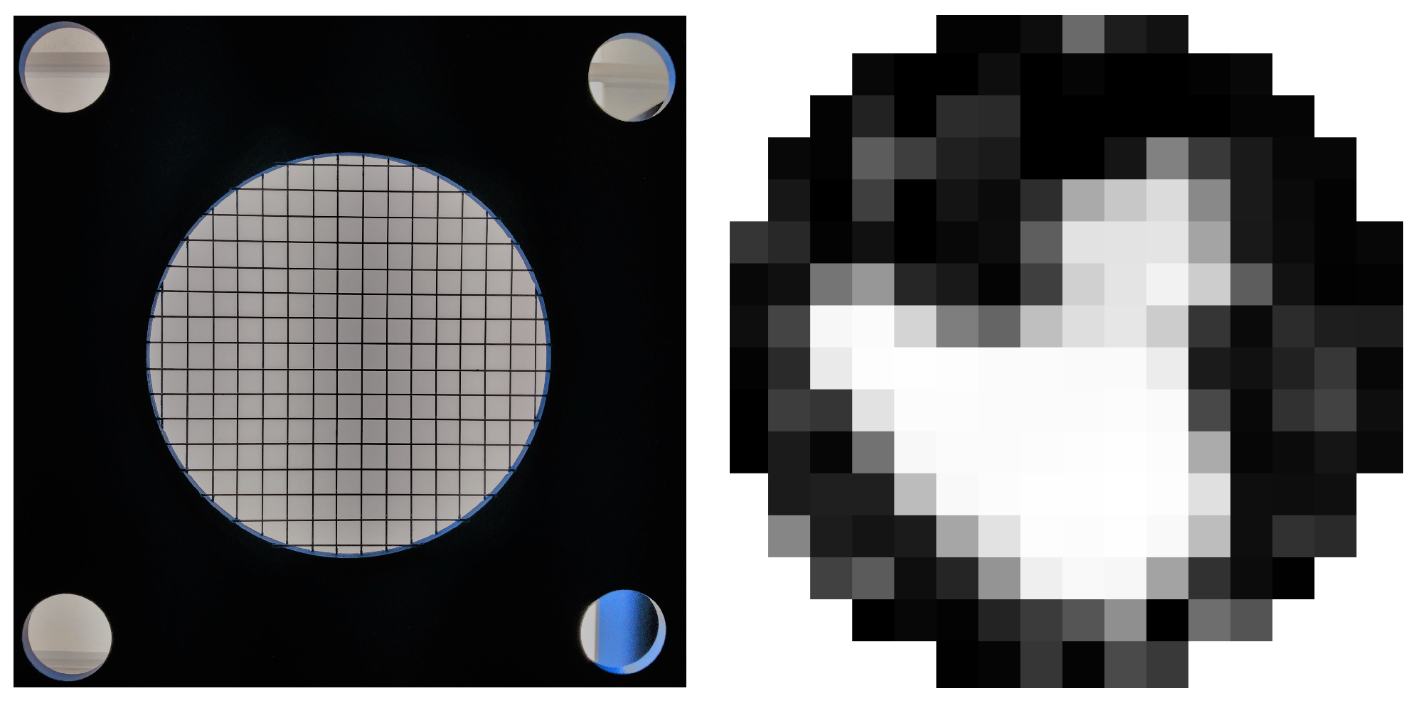
3.2. The Double-Layer Wire-Mesh Sensor
3.3. High-Speed Camera
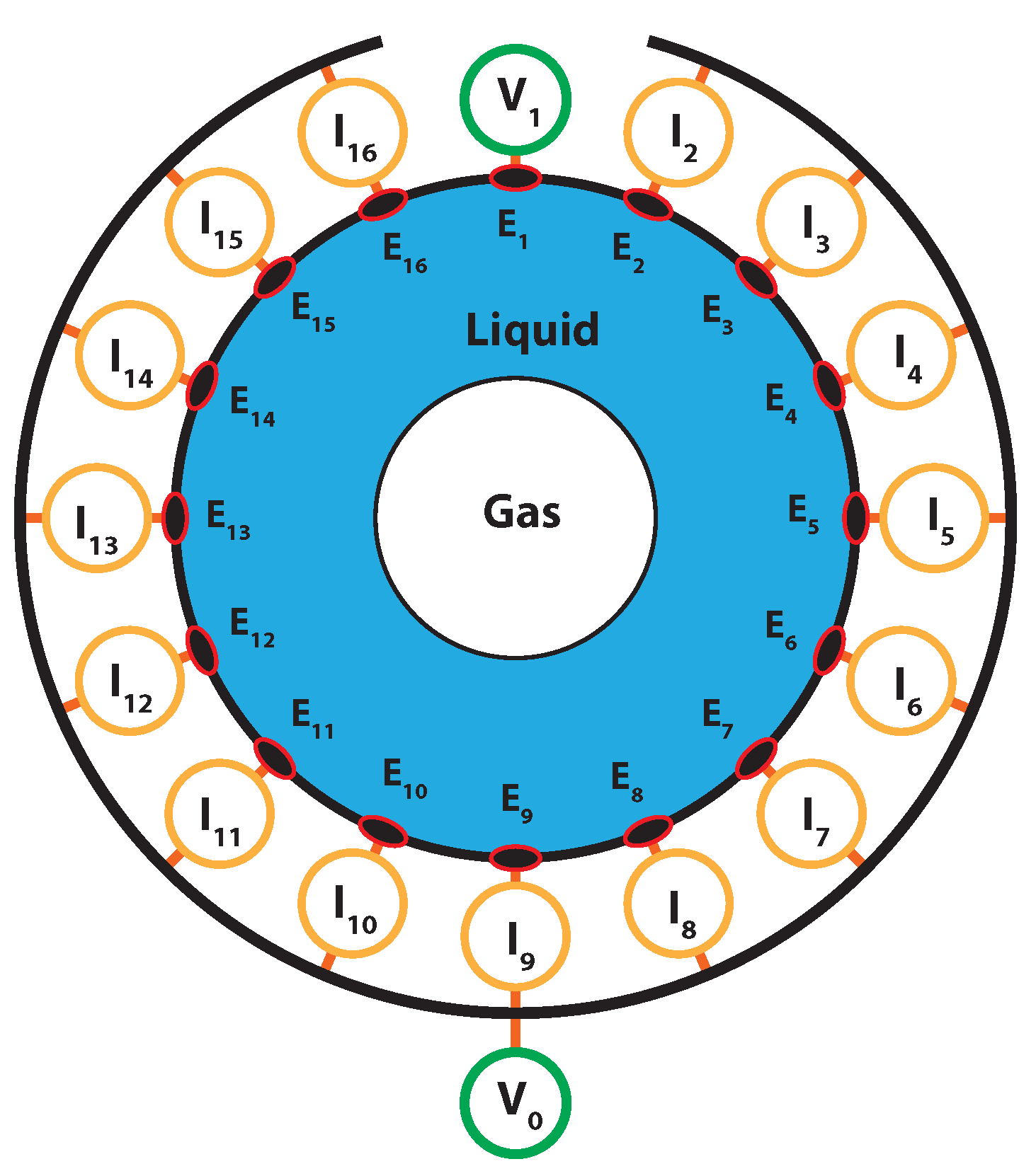
3.4. The Real-Time Electrical Resistance Tomography Sensor
3.5. Actuators and Control
4. Multiphase Flow Dynamics
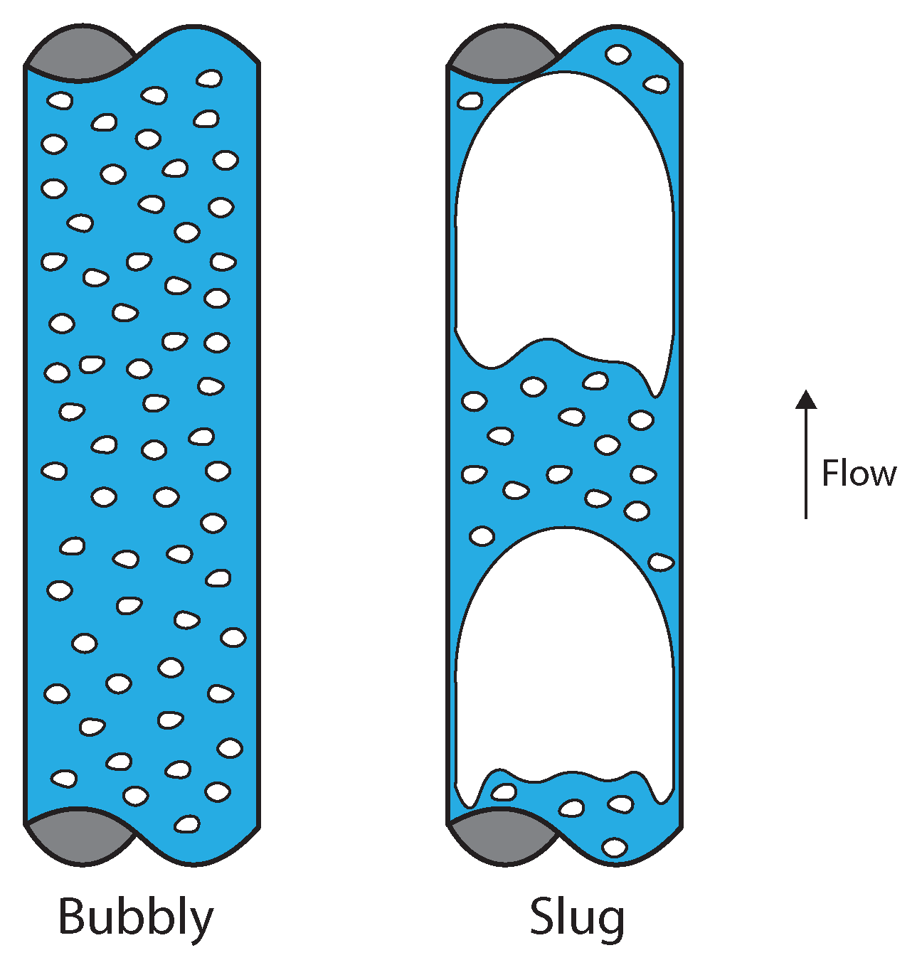
4.1. Vertical Non-Swirling Gas–Liquid Flow Patterns
4.2. Swirling Gas–Liquid Flow Patterns
4.3. Experimental Investigation of the Swirl Effects in the Upstream Flow
4.4. Numerical Simulations of the Separation
5. The Real-Time Control of Multiphase Flows
5.1. Control in the Absence of External Process Disturbances
5.2. Control in the Presence of Process Disturbances
6. Perspective
6.1. Upstream Flow and Predictive Controllers
6.2. The Time Scales of Multiphase Flow Processes and the Design of Real-Time Controllers
- Safety: Fast actions in the flow, matching the time scales of the intrinsic dynamics, can result in dangerous situations, especially when dealing with liquids. As liquids are incompressible and have large densities, sudden changes in valves can cause water hammer effects and pressure spikes in the system, which can damage the equipment and result in cracks and leakages.
- The high inertia of industrial equipment: Industrial equipment typically stores large masses of liquid, which must be accelerated whenever a change is made in the boundary conditions of the system (e.g., a change in the opening of a valve). Therefore, even if an actuator fast enough to match the time scales of the intrinsic dynamics can be used in the application, the high inertia of the system often leads to a flow response too slow in relation to the intrinsic dynamics.
- Nonlinearities and robustness: Multiphase flows are nonlinear by nature, and nonlinearities in industrial equipment are also common. For instance, the control valves of the ISS used in this study have a strong hysteresis and a nonlinear impact on the flow. Therefore, it is hard to design a controller that is stable in practice and operates in the time scales of the intrinsic dynamics, especially without a careful analysis of the physics behind the process.
6.3. The Effects of the Intrinsic Dynamics in the Operating Point of the System and Controller Performance
6.4. Application-Specific Tomography and the Monitoring of Intrinsic Dynamics
7. Conclusions
- The distribution of phases in multiphase flows has two unsteady components: (i) the intrinsic dynamics, connected to the multiphase flow patterns, and (ii) the extrinsic dynamics, associated with external process disturbances.
- The intrinsic dynamics of the distribution of phases inside industrial equipment is connected to the intrinsic dynamics of the flow upstream of the equipment, due to the conservation of mass. Therefore, feedforward actions or model predictive controllers can be designed based on the measurement of the inlet of the equipment, either using tomographic or non-tomographic (as wire-mesh sensor) techniques.
- The choice between controlling the intrinsic dynamics of the flow, or limiting the control to external process disturbances, must be performed based on the knowledge of the time scales of the intrinsic dynamics, the temporal resolution of the sensor, and the time scales of the system in relation to control actions.
- If not controlled, the intrinsic dynamics strongly influences the choice of the operating point of the system and the controller setpoint, weakens the link between the filtered distribution of phases and performance (e.g., efficiency), and limits the improvements in performance that can be achieved by controlling the process.
- Classical tomographic reconstruction techniques are too slow to monitor the intrinsic dynamics of multiphase flows in real-time, and application-specific algorithms must be developed to improve the temporal resolution of the technique in control applications.
- Tomography can be applied in the real-time control of the distribution of phases of quasi-1D multiphase flows, illustrated in this paper by the successful rejection of external disturbances in the gas core by the ERT-based PI controller implemented in the inline swirl separator.
- The control multiphase flow systems using tomography has the potential of substantially increasing the performance of the process; when rejecting external process disturbances, the ERT-based PI controller implemented in the inline swirl separator increased the capture of air by the pickup tube from 76% to 93% of the total flow rate injected in the system (an increase of 17%) and the mean efficiency of the process from 75% to 78%.
Author Contributions
Funding
Institutional Review Board Statement
Informed Consent Statement
Data Availability Statement
Acknowledgments
Conflicts of Interest
Abbreviations
| mv | Measured value |
| CFD | Computational fluid dynamics |
| ERT | Electrical resistance tomography |
| ISS | Inline swirl separator |
| PI | Proportional–integral |
| UDP | User datagram protocol |
| WMS | Wire-mesh sensor |
Appendix A. Experimental Points of the Upstream–Core Connection
| Flow Rate of Water (L/min) | Flow Rate of Air (Ln/min) |
|---|---|
| 80 | 20, 30, 40, 50, 70 |
| 100 | 30, 40, 50, 70, 90 |
| 120 | 40, 50, 70, 90, 110 |
| 140 | 50, 70, 90, 110, 130 |
| 150 | 20, 30, 40, 50, 60 |
| 150 | 70, 90, 110, 130, 150 |
| 160 | 90, 110, 130, 150, 170 |
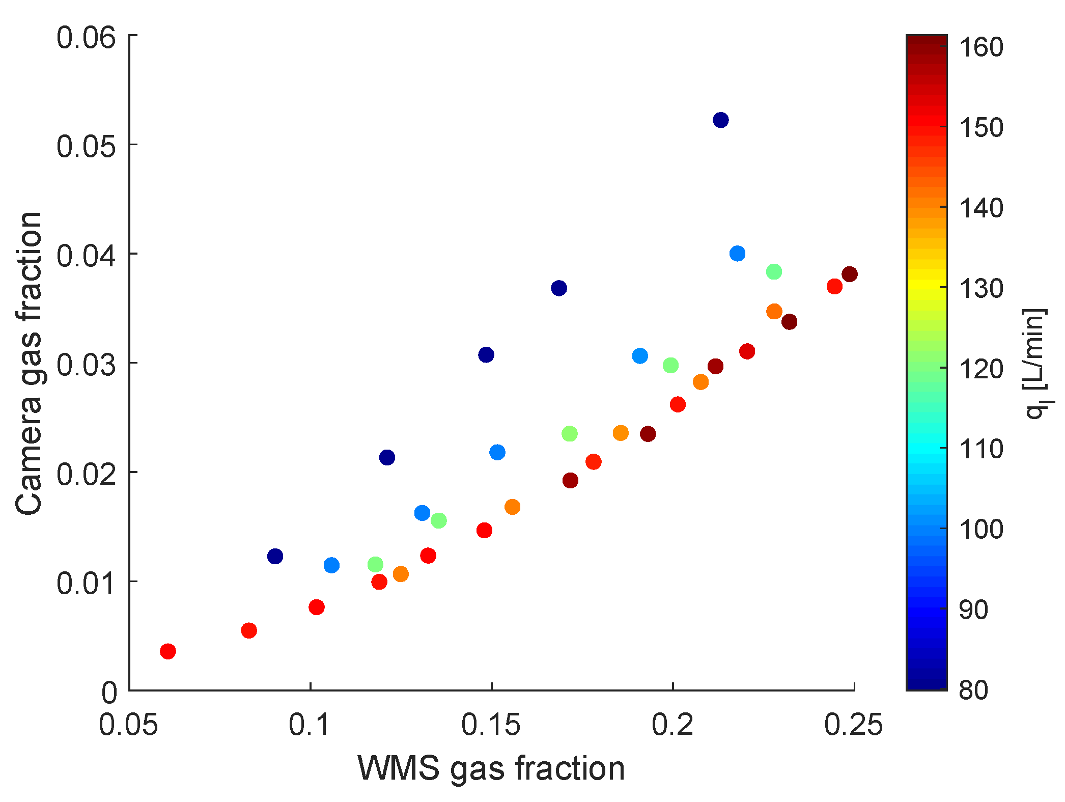
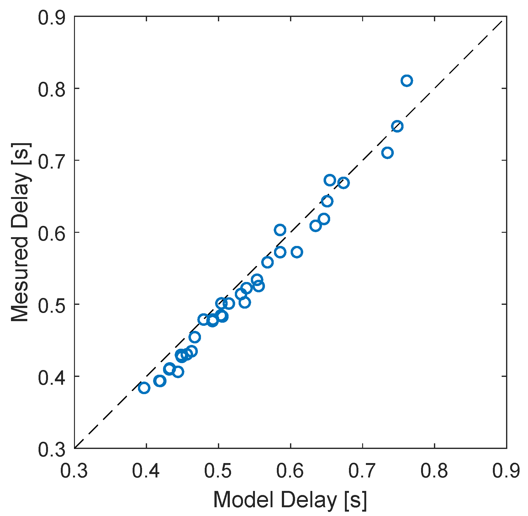
Appendix B. Estimation of the Wire-Mesh Sensor–Camera Delay
- i.
- The gas moves at the speed detected by the wire-mesh sensor () between the wire-mesh sensor and the swirl element, leading to .
- ii.
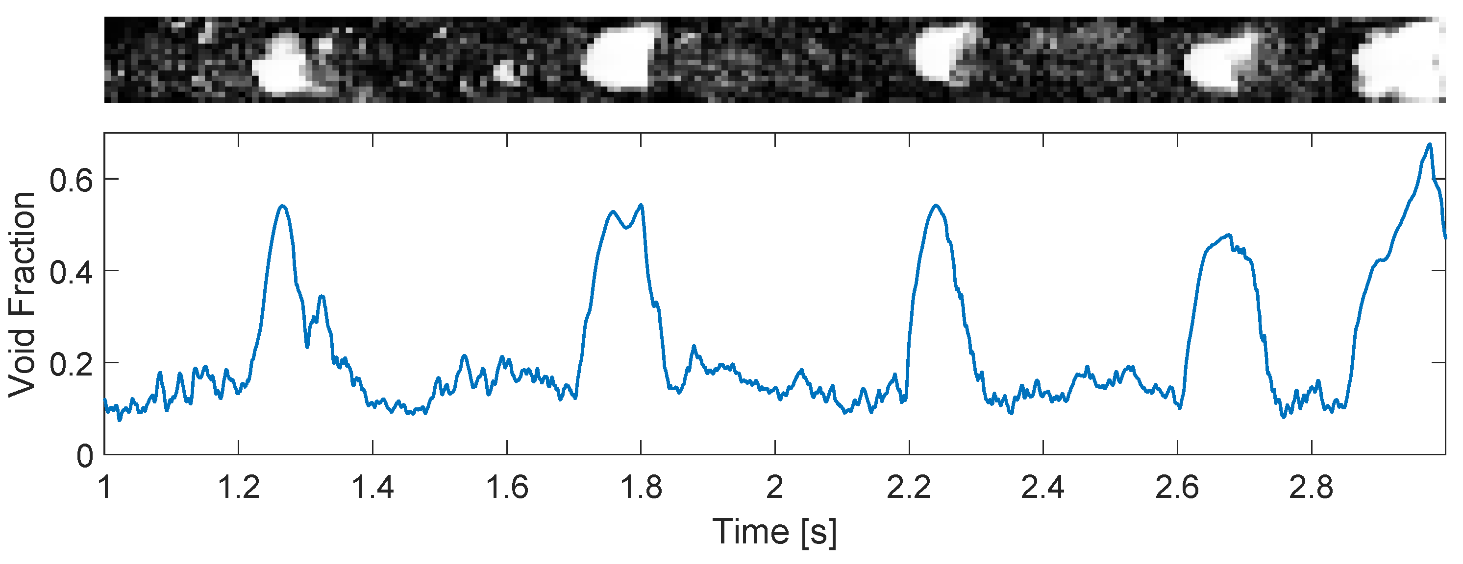
- The body of the swirl element (se) causes a contraction of the flow, which leads to a mixture velocity inside the vanes of the swirl element larger than in the pipe below it. The mixture velocity is defined as the total flow rate divided by the cross-sectional area of the flow. Since the total flow rate is the same both upstream and inside the vanes, the mixture velocity of the two locations are connected by:where A is the cross-sectional area of the pipe, is the cross-sectional area of the flow in the swirl element, and is the mixture velocity in the pipe.Considering a drift-flux model, the velocity of the gas in the flow is given by a term proportional to the mixture velocity plus a slip velocity:where C and are constants, which depend on the flow pattern.Figure A1 shows the relation obtained between gas velocity, detected by the double-layer wire-mesh sensor, and the mixture velocity, calculated based on the flow rates of liquid and gas at the location of the wire-mesh, for the points of Appendix A, in which slug flow is observed in the experiments. A least-squares fit of the graph based on the drift-flux model () leads to and m/s.The flow patterns inside the vanes of the swirl element are unknown, and it is assumed that the upstream flow patterns (typically slug) are maintained during the passage of the flow through the swirl element, which allows computing the gas velocity based on the same drift-flux coefficients of the upstream flow:with and m/s when the slug flow is observed upstream of the swirl element.Instead of using , which is flow pattern dependent, the expression can be manipulated to include the wire-mesh sensor velocity explicitly, making it independent of the flow pattern (as long as the hypothesis of the maintenance of the upstream flow pattern along the vanes of the swirl element is still valid):leading to for the experimental facility (the area ratio is equal to 1.84 from the geometry of the swirl element). The delay across the swirl element is given by its length divided by the gas velocity, i.e., .
- iii.
- The gas moves at speed between the swirl element outlet and the camera, where is the area of the gas core measured by the camera (). Therefore, .


References
- Grabenstein, V.; Polzin, A.E.; Kabelac, S. Experimental investigation of the flow pattern, pressure drop and void fraction of two-phase flow in the corrugated gap of a plate heat exchanger. Int. J. Multiph. Flow 2017, 91, 155–169. [Google Scholar] [CrossRef]
- Amalfi, R.L.; Vakili-Farahani, F.; Thome, J.R. Flow boiling and frictional pressure gradients in plate heat exchangers. Part 1: Review and experimental database. Int. J. Refrig. 2016, 61, 166–184. [Google Scholar] [CrossRef]
- Besagni, G.; Inzoli, F.; Ziegenhein, T. Two-Phase Bubble Columns: A Comprehensive Review. ChemEngineering 2018, 2, 13. [Google Scholar] [CrossRef]
- Zeng, X.; Zhao, L.; Zhao, W.; Hou, M.; Zhu, F.; Fan, G.; Yan, C. Experimental Study on a Novel Axial Separator for Oil–Water Separation. Ind. Eng. Chem. Res. 2020, 59, 21177–21186. [Google Scholar] [CrossRef]
- Liu, S.; Yan, Y.; Gao, Y. Optimization of geometry parameters with separation efficiency and flow split ratio for downhole oil-water hydrocyclone. Therm. Sci. Eng. Prog. 2018, 8, 370–374. [Google Scholar] [CrossRef]
- Yin, J.; Li, J.; Ma, Y.; Li, H.; Liu, W.; Wang, D. Study on the Air Core Formation of a Gas–Liquid Separator. ASME J. Fluids Eng. 2015, 137, 091301. [Google Scholar] [CrossRef]
- Funahashi, H.; Hayashi, K.; Hosokawa, S.; Tomiyama, A. Study on two-phase swirling flows in a gas–liquid separator with three pick-off rings. Nucl. Eng. Des. 2016, 308, 205–213. [Google Scholar] [CrossRef]
- Shah, Y.; Kelkar, B.G.; Godbole, S.; Deckwer, W.D. Design parameters estimations for bubble column reactors. AICHE J. 1982, 28, 353–379. [Google Scholar] [CrossRef]
- Besagni, G.; Inzoli, F. The effect of liquid phase properties on bubble column fluid dynamics: Gas holdup, flow regime transition, bubble size distributions and shapes, interfacial areas and foaming phenomena. Chem. Eng. Sci. 2017, 170, 270–296. [Google Scholar] [CrossRef]
- Bordalo, S.N.; Morooka, C.K. Slug flow induced oscillations on subsea petroleum pipelines. J. Pet. Sci. Eng. 2018, 165, 535–549. [Google Scholar] [CrossRef]
- Klinkenberg, A.M.; Tijsseling, A.S. Stochastic mechanistic modelling of two-phase slug flow forces on bends in horizontal piping. Int. J. Multiph. Flow 2021, 144, 103778. [Google Scholar] [CrossRef]
- Zhang, Z.; Bieberle, M.; Barthel, F.; Szalinski, L.; Hampel, U. Investigation of upward cocurrent gas–liquid pipe flow using ultrafast X-ray tomography and wire-mesh sensor. Flow Meas. Instrum. 2013, 32, 111–118. [Google Scholar] [CrossRef]
- Vieira, R.E.; Kesana, N.R.; Torres, C.F.; McLaury, B.S.; Shirazi, S.A.; Schleicher, E.; Hampel, U. Experimental Investigation of Horizontal Gas–Liquid Stratified and Annular Flow Using Wire-Mesh Sensor. J. Fluids Eng. 2014, 136, 121301. [Google Scholar] [CrossRef]
- Silva, M.J.D.; dos Santos, E.N.; Hampel, U.; Rodriguez, I.H.; Rodriguez, O.M.H. Phase fraction distribution measurement of oil–water flow using a capacitance wire-mesh sensor. Meas. Sci. Technol. 2011, 22, 104020. [Google Scholar] [CrossRef]
- Rodriguez, I.; Velasco Peña, H.; Bonilla Riaño, A.; Henkes, R.; Rodriguez, O. Experiments with a Wire-Mesh Sensor for stratified and dispersed oil-brine pipe flow. Int. J. Multiph. Flow 2015, 70, 113–125. [Google Scholar] [CrossRef]
- dos Santos, E.N.; Vendruscolo, T.P.; Morales, R.E.M.; Schleicher, E.; Hampel, U.; Silva, M.J.D. Dual-modality wire-mesh sensor for the visualization of three-phase flows. Meas. Sci. Technol. 2015, 26, 105302. [Google Scholar] [CrossRef]
- Velasco Peña, H.; Rodriguez, O. Applications of wire-mesh sensors in multiphase flows. Flow Meas. Instrum. 2015, 45, 255–273. [Google Scholar] [CrossRef]
- Liu, S.; Yang, L.-L.; Zhang, D.; Xu, J.-Y. Separation characteristics of the gas and liquid phases in a vane-type swirling flow field. Int. J. Multiph. Flow 2018, 107, 131–145. [Google Scholar] [CrossRef]
- Sharifi, M.; Young, B. Electrical resistance tomography (ERT) applications to chemical engineering. Chem. Eng. Res. Des. 2013, 91, 1625–1645. [Google Scholar] [CrossRef]
- Almutairi, Z.; Al-Alweet, F.M.; Alghamdi, Y.A.; Almisned, O.A.; Alothman, O.Y. Investigating the Characteristics of Two-Phase Flow Using Electrical Capacitance Tomography (ECT) for Three Pipe Orientations. Processes 2020, 8, 51. [Google Scholar] [CrossRef]
- Banasiak, R.; Wajman, R.; Jaworski, T.; Fiderek, P.; Fidos, H.; Nowakowski, J.; Sankowski, D. Study on two-phase flow regime visualization and identification using 3D electrical capacitance tomography and fuzzy-logic classification. Int. J. Multiph. Flow 2014, 58, 1–14. [Google Scholar] [CrossRef]
- Dang, C.; Darnajou, M.; Bellis, C.; Ricciardi, G.; Mylvaganam, S.; Bourennane, S. Improving EIT-Based Visualizations of Two-Phase Flows Using an Eigenvalue Correlation Method. IEEE Trans. Instrum. Meas. 2021, 70, 1–9. [Google Scholar] [CrossRef]
- Daidzic, N.; Schmidt, E.; Hasan, M.; Altobelli, S. Gas–liquid phase distribution and void fraction measurements using MRI. Nucl. Eng. Des. 2005, 235, 1163–1178. [Google Scholar] [CrossRef]
- Gladden, L.F.; Sederman, A.J. Recent advances in Flow MRI. J. Magn. Reson. 2013, 229, 2–11. [Google Scholar] [CrossRef]
- Collins, J.H.; Sederman, A.J.; Gladden, L.F.; Afeworki, M.; Douglas Kushnerick, J.; Thomann, H. Characterising gas behaviour during gas–liquid co-current up-flow in packed beds using magnetic resonance imaging. Chem. Eng. Sci. 2017, 157, 2–14. [Google Scholar] [CrossRef]
- Tan, C.; Murai, Y.; Liu, W.; Tasaka, Y.; Dong, F.; Takeda, Y. Ultrasonic Doppler Technique for Application to Multiphase Flows: A Review. Int. J. Multiph. Flow 2021, 144, 103811. [Google Scholar] [CrossRef]
- Liang, F.; Fang, Z.; Chen, J.; Sun, S. Investigating the liquid film characteristics of gas–liquid swirling flow using ultrasound doppler velocimetry. AIChE J. 2017, 63, 2348–2357. [Google Scholar] [CrossRef]
- Durdevic, P.; Pedersen, S.; Bram, M.; Hansen, D.; Hassan, A.; Yang, Z. Control Oriented Modeling of a De-oiling Hydrocyclone. IFAC Pap. 2015, 48, 291–296. [Google Scholar] [CrossRef]
- Aamo, O.; Eikrem, G.; Siahaan, H.; Foss, B. Observer design for multiphase flow in vertical pipes with gas-lift—Theory and experiments. J. Process. Control 2005, 15, 247–257. [Google Scholar] [CrossRef]
- Nnabuife, S.G.; Tandoh, H.; Whidborne, J.F. Slug flow control using topside measurements: A review. Chem. Eng. J. Adv. 2022, 9, 100204. [Google Scholar] [CrossRef]
- Cheng, H.; Hills, J.; Azzorpardi, B. A study of the bubble-to-slug transition in vertical gas–liquid flow in columns of different diameter. Int. J. Multiph. Flow 1998, 24, 431–452. [Google Scholar] [CrossRef]
- Kaji, R.; Azzopardi, B.; Lucas, D. Investigation of flow development of co-current gas–liquid vertical slug flow. Int. J. Multiph. Flow 2009, 35, 335–348. [Google Scholar] [CrossRef]
- Hampel, U.; Babout, L.; Banasiak, R.; Schleicher, E.; Soleimani, M.; Wondrak, T.; Vauhkonen, M.; Lähivaara, T.; Tan, C.; Hoyle, B.; et al. A Review on Fast Tomographic Imaging Techniques and Their Potential Application in Industrial Process Control. Sensors 2022, 22, 2309. [Google Scholar] [CrossRef] [PubMed]
- Rymarczyk, T.; Sikora, J. Applying industrial tomography to control and optimization flow systems. Open Phys. 2018, 16, 332–345. [Google Scholar] [CrossRef]
- Sattar, M.A.; Garcia, M.M.; Banasiak, R.; Portela, L.M.; Babout, L. Electrical Resistance Tomography for Control Applications: Quantitative Study of the Gas–Liquid Distribution inside A Cyclone. Sensors 2020, 20, 6069. [Google Scholar] [CrossRef]
- Sattar, M.A.; Garcia, M.M.; Portela, L.M.; Babout, L. A Fast Electrical Resistivity-Based Algorithm to Measure and Visualize Two-Phase Swirling Flows. Sensors 2022, 22, 1834. [Google Scholar] [CrossRef]
- Slot, J. Development of a Centrifugal in-Line Separator for Oil-Water Flows. Ph.D. Thesis, University of Twente, Enschede, The Netherlands, 2013. [Google Scholar] [CrossRef]
- Yin, J.; Qian, Y.; Ma, Y.; Wang, D. Experimental study on the bubble trajectory in an axial gas–liquid separator applied for tritium removal for molten salt reactors. Nucl. Eng. Des. 2017, 320, 133–140. [Google Scholar] [CrossRef]
- Ochowiak, M.; Matuszak, M.; Włodarczak, S.; Ancukiewicz, M.; Krupińska, A. The modified swirl sedimentation tanks for water purification. J. Environ. Manag. 2017, 189, 22–28. [Google Scholar] [CrossRef]
- Sahovic, B.; Atmani, H.; Sattar, M.A.; Garcia, M.M.; Schleicher, E.; Legendre, D.; Climent, E.; Zamansky, R.; Pedrono, A.; Babout, L.; et al. Controlled Inline Fluid Separation Based on Smart Process Tomography Sensors. Chem. Ing. Tech. 2020, 92, 554–563. [Google Scholar] [CrossRef]
- Prasser, H.M.; Böttger, A.; Zschau, J. A new electrode-mesh tomograph for gas–liquid flows. Flow Meas. Instrum. 1998, 9, 111–119. [Google Scholar] [CrossRef]
- Alekseenko, S.; Kuibin, P.; Okulov, V.L.; Shtork, S. Helical vortices in swirl flow. J. Fluid Mech. 1999, 382, 195–243. [Google Scholar] [CrossRef]
- Otsu, N. A threshold selection method from gray-level histograms. IEEE Trans. Syst. Man Cybern. 1979, 9, 62–66. [Google Scholar] [CrossRef]
- Taitel, Y.; Bornea, D.; Dukler, A.E. Modelling flow pattern transitions for steady upward gas–liquid flow in vertical tubes. AIChE J. 1980, 26, 345–354. [Google Scholar] [CrossRef]
- Liu, L.; Bai, B. Flow regime identification of swirling gas–liquid flow with image processing technique and neural networks. Chem. Eng. Sci. 2019, 199, 588–601. [Google Scholar] [CrossRef]
- Ammerlaan, D. Swirl Effects on Vertical Gas–Liquid Flow Regimes: Experiments and Modelling. Master’s Thesis, Delft University of Technology, Delft, The Netherlands, 2021. [Google Scholar]
- Atmani, H.; Zamansky, R.; Climent, E.; Legendre, D. CFD approach to simulate two phase flow inline-separator coupling IBM, LES, Lagrangian tracking and VoF methods. In Proceedings of the 14th International Conference on CFD in 6 Oil & Gas, Metallurgical and Process Industries SINTEF, Trondheim, Norway, 12–14 October 2020. [Google Scholar]
- Chouippe, A.; Climent, E.; Legendre, D.; Gabillet, C. Numerical simulations of bubble dispersion in turbulent Taylor Couette flow. Phys. Fluids 2014, 26, 043304. [Google Scholar] [CrossRef]
- Atmani, H. Hybrid CFD Simulations of Two-Phase Flows in Inline Flow Splitters. Ph.D. Thesis, University of Toulouse, Toulouse, France, 2022. [Google Scholar]
- Bigot, B.; Bonometti, T.; Thual, O.; Lacaze, L. A simple immersed boundary method for solid fluid interaction in constant and stratified density flows. J. Comput. Fluids 2014, 97, 126–142. [Google Scholar] [CrossRef]
- Calmet, I.; Magnaudet, J. Large eddy simulation of high Schmidt number mass transfer in a turbulent channel flow. Phys. Fluids 1997, 9, 438–455. [Google Scholar] [CrossRef]
- Atmani, H.; Zamansky, R.; Climent, E.; Legendre, D. Stochastic wall model for turbulent pipe flow using Immersed Boundary Method and Large Eddy Simulation. J. Comput. Fluids 2021, 239, 105419. [Google Scholar] [CrossRef]
- Garcia, M.; Sahovic, B.; Sattar, M.; Atmani, H.; Schleicher, E.; Hampel, U.; Babout, L.; Legendre, D.; Portela, L. Control of a Gas–Liquid Inline Swirl Separator Based on Tomographic Measurements. IFAC-Pap. 2020, 53, 11483–11490. [Google Scholar] [CrossRef]








| Experiment | |||||
|---|---|---|---|---|---|
| Operating Point (Figure 22) | 0.0724 | 0.0146 | 88% | 74% | 81% |
| Control of Intrinsic Dynamics (Figure 23) | 0.0719 | 0.0154 | 92% | 70% | 81% |
| Uncontrolled Disturbance (Figure 24) | 0.0902 | 0.0323 | 76% | 75% | 75% |
| Control of Disturbance (Figure 25) | 0.0801 | 0.0227 | 93% | 63% | 78% |
Publisher’s Note: MDPI stays neutral with regard to jurisdictional claims in published maps and institutional affiliations. |
© 2022 by the authors. Licensee MDPI, Basel, Switzerland. This article is an open access article distributed under the terms and conditions of the Creative Commons Attribution (CC BY) license (https://creativecommons.org/licenses/by/4.0/).
Share and Cite
Garcia, M.M.; Sattar, M.A.; Atmani, H.; Legendre, D.; Babout, L.; Schleicher, E.; Hampel, U.; Portela, L.M. Towards Tomography-Based Real-Time Control of Multiphase Flows: A Proof of Concept in Inline Fluid Separation. Sensors 2022, 22, 4443. https://doi.org/10.3390/s22124443
Garcia MM, Sattar MA, Atmani H, Legendre D, Babout L, Schleicher E, Hampel U, Portela LM. Towards Tomography-Based Real-Time Control of Multiphase Flows: A Proof of Concept in Inline Fluid Separation. Sensors. 2022; 22(12):4443. https://doi.org/10.3390/s22124443
Chicago/Turabian StyleGarcia, Matheus M., Muhammad A. Sattar, Hanane Atmani, Dominique Legendre, Laurent Babout, Eckhard Schleicher, Uwe Hampel, and Luis M. Portela. 2022. "Towards Tomography-Based Real-Time Control of Multiphase Flows: A Proof of Concept in Inline Fluid Separation" Sensors 22, no. 12: 4443. https://doi.org/10.3390/s22124443
APA StyleGarcia, M. M., Sattar, M. A., Atmani, H., Legendre, D., Babout, L., Schleicher, E., Hampel, U., & Portela, L. M. (2022). Towards Tomography-Based Real-Time Control of Multiphase Flows: A Proof of Concept in Inline Fluid Separation. Sensors, 22(12), 4443. https://doi.org/10.3390/s22124443


