
An Underwater Cooperative Spectrum Sharing Protocol for a Centralized Underwater Cognitive Acoustic Network


Abstract
:1. Introduction
- The definition of a CU and an NCU in the underwater acoustic frequency band;
- The strategy of spectrum sharing in the time and frequency domains;
- The strategy of cooperation among CUs or NCUs;
- Network topology.
- A UCAN with a centralized topology, which consisted of a central entity and several CUs, was considered;
- As specified in [8], the underwater acoustic frequency band was divided into multiple channels. Some of the channels are used as a control channel and others are used as a data channel. Hence, a data channel becomes a resource for a CU in UCSS protocol;
- A CU transmits the activity status of its neighboring NCUs occurring at all data channels (e.g., natural or artificial interferers) to a central entity on a control channel. The central entity allocates them into data channels according to their quality of service (QoS).
- The description of considerations for the purpose of designing a spectrum sharing protocol for a UCAN. These considerations can also be commonly employed to propose other protocols for a UCAN (e.g., spectrum mobility or spectrum access);
- The design of a heuristic spectrum sharing protocol that includes both resource allocation and time domain division methods. This work differs from most of the previous works on UCANs, because they have not dealt with practical issues such as setting the ratio of sensing and non-sensing sub-frames, the resource allocation methods such as the priority-based allocation ordering, or the allocation methods (i.e., MRRA or SRRA);
- A performance analysis of the UCSS protocol via extensive simulations and suggesting an efficient resource allocation method for a UCAN as well as the ratio of a sensing sub-frame to a non-sensing sub-frame in the time domain.
2. Previous Works on Spectrum Sharing for a UCAN
- In [19], a dolphin-aware data transmission (DAD-Tx) technique was proposed for a multi-hop underwater communication network. The DAD-Tx is ecofriendly in that it designs the optimized transmission schedules of CUs to maximize the end-to-end throughput as well as to reduce the impact on dolphins. To do so, the authors modeled the stochastic characteristic of dolphins’ communications which is used as a constraint of the optimization problem;
- In [20], a resource allocation method in consideration of the traffic characteristics of neighboring sender CUs under a fixed distributed network topology. In particular, a receiver CU adaptively determines the transmission period of the neighboring sender CUs on the basis of their traffic conditions. The receiver CU also allocates the sender CUs into the channel and transmits power to maximize their transmission rate;
- In [21], a receiver-viewed dynamic borrowing (RvDV) algorithm, a heuristic spectrum decision method among cluster heads in a cluster-based underwater sensor network was proposed. In this algorithm, a cluster head can borrow additional spectrum resources for data transmission from neighboring cluster heads by informing them of its traffic information in the control channel;
- In [22], a dynamic spectrum access considering the CR concept was proposed to utilize the limited acoustic frequency resources more efficiently. Under the assumption that the number of CUs is the same as the number of channels, a heuristic algorithm that determines the CU–channel pairs to maximize the minimum channel capacity per CU by applying graph theory was proposed. Through simulations, it was confirmed that this algorithm improved the fairness and the spectrum’s efficiency, compared to an FDMA which allocates fixed frequency resources;
- In [23], a dynamic control channel (DCC)-MAC was proposed where CUs adaptively adjust the bandwidth used for controlling according to their traffic for a distributed acoustic network. When congestion is detected in the control channel, a CU modifies the bandwidth of the data channel in order to increase the bandwidth for the control channel. The congestion is determined by the frequency of collisions that the CU experiences;
- In [24], an OFDM-based distributed underwater network considering cognitive acoustics was modeled as a noncooperative game. That is, any CU in the network becomes a player and tries to allocate optimal transmit power to each subcarrier of the OFDM system. To do so, each player allocates transmit power to optimize the utility function related to the information rate. It was shown that efficient decentralized spectrum sharing can be achieved when all players use a water-filling strategy against each other;
- In [25], a method for CUs to allocate their own channels unoccupied by NCUs (i.e., natural and artificial interferers) in a distributed underwater network was proposed. A sender CU senses the availability of channels in the current slot and transmits an RTS packet to a receiver CU, and the receiver CU selects an optimal channel that can maximize the channel sharing reward and transmits a CTS packet. If the assigned channel from the receiver CU is still available, the sender CU can transmit data on the allocated channel;
- In [26], a spectrum allocation method in which a CU allocates its own channel among subcarriers unoccupied by all NCUs by itself in an OFDMA-based underwater network. In this method, the CU selects a subcarrier capable of optimizing the overall energy efficiency by considering the spectrum sensing errors and the uncertainty of channel state information (CSI).
- In [27], a joint channel and power allocation method in an OFDM-based UACN was proposed. In this study, the joint channel and power allocation is formulated as an optimization problem to minimize the maximum outage probability. To solve this problem, two proposed algorithms are interchangeably employed: robust distributed power allocation (RDPA) and robust channel selection (RCS) algorithms;
- In [28], an efficient spectrum management scheme was proposed in order to fulfill environmentally friendly and spectrum-efficient communication for UCANs. In this study, a receiver CU assigns the channel and power to a sender CU based on the channel gain information received from the sender CU. That is, the receiver CU determines the joint channel and power of the sender CU to maximize the total channel capacity;
- In [29], a joint relay selection and power allocation method for a UCAN where the data from CUs are forwarded by multiple relays (i.e., AUVs) was presented. In this study, the joint relay and power selection problem is solved by considering the limited feedback of quantized CSI information to obtain the maximum sum rate;
- In [30], another joint relay selection and power allocation method was proposed for a UCAN, which considers a trust parameter to overcome imperfect spectrum sensing. In this study, selecting a relay CU and allocating power are determined to maximize the network throughput, and this optimization problem is reduced to the proposed sub-optimal approach;
- In [31], the joint parameter optimization of cooperative spectrum sensing time, channel allocation, and power for a UCAN was proposed in order to maximize spectral efficiency and energy efficiency at the same time. The optimal solutions are obtained by alternating direction optimization and Dinkelbach’s optimization;
- In [32], a QoS-driven power allocation method for a UCAN was proposed, which helps to allocate a CU into an optimal power by considering the statistical QoS constraints (i.e., delay bounds). That is, a CU adjusts the transmit power adaptively in consideration of QoS in the transmission mode.
- In [33], an efficient bandwidth-aware routing was proposed to improve the throughput and spectral efficiency of a UCAN. In this study, an optimization problem is derived to maximize the spectrum utilization by taking into account the bandwidth requirement of CUs and analyzing the activities of NCUs under the assumption of an ON–OFF channel model;
- In [9], a marine mammal-friendly based high spectral-efficient routing (MF-HER) protocol was proposed to improve spectrum utilization and protect underwater animals for underwater acoustic sensor networks. In this study, the detour route is determined among the multiple routes to exclude the route where any animals are detected;
- In [12], a study was conducted that modeled and analyzed the connectivity and coverage of CUs in a distributed underwater network in order to guarantee their QoS. The analytic model was also verified via simulations, and it was confirmed that the connectivity and coverage of CUs were affected by external factors such as acoustic frequency, spreading factor, wind speed, and the activity of NCUs;
- In [34], a UCAN framework that can improve spectrum utilization by avoiding underwater natural and artificial interferers was proposed. In addition, the strategy to design a framework is specified in terms of sensing, sharing, power control, interferer classification, and spectrum management;
- In [35], an ecofriendly framework to assign spectrum by predicting the interference with underwater animals was proposed. The framework consists of four phases: preliminary knowledge acquisition regarding marine mammals, channel availability prediction, channel assignment, and transmission and channel evaluation. The authors also covered the evaluation metrics and overall implementation challenges of the framework.
3. Considerations and a Scenario of Spectrum Sharing for a UCAN
3.1. A Cognitive User and a Noncognitive User of the Underwater Acoustic Frequency Band
3.2. The Strategy of Spectrum Sharing in Terms of the Time and Frequency Domains
3.3. The Strategy for Cooperation among CUs and NCUs
3.4. Network Topology
3.5. Scenario
3.5.1. Topology and Channels
3.5.2. Spectrum Sharing Processes
- Spectrum sensing is a process where all CUs detect the status of their neighboring NCUs on the acoustic frequency band;
- Gathering sensing information is a process where a CU provides sensing information to a central entity through a control channel, and the central entity receives the sensing information sent by all CUs for resource allocation. To do so, a CU transmits the activity state of its neighboring NCUs to a central entity as shown in Figure 1b. In addition to the activity state information, a CU can send its QoS information which is also employed to allocate its resource;
- Resource allocation is a process where a central entity determines the proper resources of a CU by considering all the received information and informs the CU of the indexes of data channels via a control channel as illustrated in Figure 1c;
- Spectrum use is a process where a CU uses its data channels assigned by a central entity as shown in Figure 1d. If the allocated data channel is no longer available due to the occurrence of new NCUs, the CU should request another data channel from the central entity;
- The state transition diagram of spectrum sharing processes is depicted in Figure 1e, which shows the flow of spectrum sharing in a UCAN.
4. UCSS Protocol
4.1. Division of the Frequency and Time Domains
4.2. Resource Allocation
4.2.1. Information of Resource Allocation
4.2.2. Allocation Orders
- P1 order: Random allocation order. The allocation order of a CU is randomly determined;
- P2 order: Fixed allocation order. Once the allocation order of a CU is initially set, there is no change in the order. Although this rule has low complexity, specific CUs may monopolize the overall resources;
- P3 order: High QoS priority-based allocation order. The allocation order of CUs is set in descending order of the number of required data channel (i.e., ). Namely, the greater the , the more prioritized the CU becomes. If any CUs have the same value of , their allocation order is randomly determined among them. The P3 order is intended to improve network throughput by preventing packet drops and reducing transmission delays. To do this, the P3 order provides more transmission opportunities for CUs with a higher QoS;
- P4 order: Low-channel allocation rate priority-based allocations. The allocation order of CUs is determined in ascending order of the channel allocation rate (i.e., ). The lower the , the higher the CU is prioritized. If any CUs have the same value for , their allocation order is randomly determined, the same as for the P3 order. The P4 order is proposed to increase the fairness of channel use by allocating more data channels to any CUs with lower channel allocation rates.
4.2.3. Resource Allocation Algorithms
- The set of CUs that does not finish resource allocation (i.e., ). Initially, includes the indexes of all CUs as . In addition, , the number of elements in , is applied as a criterion whether a central entity keeps executing on-going resource allocation or not. If , the current resource allocation ends due to the absence of CUs;
- The number of unallocated data channels (i.e., ). Similar to , this parameter is also used as a criterion to decide whether to terminate an ongoing allocation process. If , the resource allocation is over, since there are no allocable data channels;
- The number of required data channels for CU (i.e., ). This parameter is applied to decide the allocation order of CUs (i.e., P3 order);
- The set of the average channel allocate rates of all CUs (i.e., ). This information is also employed to determine the allocation order of a CU (i.e., P4 order);
- The set of available data channels for CU (i.e., ), which is specified in Section 4.2.1;
- The set of CUs allocated to each data channel (i.e., ), which is a () vector. The index of a CU to which the channel is allocated is stored in the element of . For example, if data channel 2 is allocated to CU 3, ) = 3.
- Step 1: There are two inputs (i.e., and ) and one output (i.e., ) for resource allocation;
- Step 2: A central entity assigns a data channel (or data channels) to a CU based on a given allocation order;
- Step 3: For CU , the central entity checks and in order to determine whether at least one of the data channels included in exists in ;
- Step 4: If there is at least one data channel for CU , the central entity allocates a data channel (or multiple data channels) to the CU. Then, the central entity updates the following information. First, if the data channel is assigned to CU , is updated as . Second, the central entity subtracts “1” from and . If the updated is zero, the central entity removes CU from . Third, the central entity adds “1” to . Fourth, the channel allocation rate in is updated using the updated and is expressed as ;
- Step 5: If there is no data channel available for CU , the CU cannot obtain any data channel in this resource allocation process. In this case, the central entity only updates by removing the index of the CU from .
- The procedures of the MRRA are described as follows:
- In this algorithm, only one data channel is assigned to a CU per round. Accordingly, if at least one data channel is unallocated even after finishing one round, the next round begins;
- As illustrated in Figure 3a, at the start of each round, a central entity determines the allocation order of all CUs as specified in Section 4.2.2;
- In one round, the central entity assigns a data channel to a CU by following the aforementioned allocation procedures (Steps 1 to 5);
- After updating the corresponding information, as specified in Steps 4 or 5, the central entity checks and . If or , it finishes the ongoing allocation process. Otherwise, the central entity determines whether the current round is finished.
- If the round is not finished, the central entity conducts the same procedures (i.e., Steps 2 to 5) in order to allocate a data channel to another CU. If the current round ends, the central entity starts to determine the allocation order again as shown in Figure 3a.
- The procedures of SRRA are explained as follows:
- In this algorithm, a central entity assigns as many data channels as its QoS to a CU. In some cases, CUs with lower priority may not be allocated as many data channels as its QoS. Even worse, they may not be allocated a data channel at all;
- As shown in Figure 3b, a central entity determines the allocation order of all CUs just once in the beginning of resource allocation;
- The central entity also allocates data channels corresponding to its QoS to a CU by applying the aforementioned allocation procedures (Steps 1 to 5);
- After updating the corresponding information as per Steps 4 or 5, the central entity checks and . If or , it finishes the ongoing allocation process. Otherwise, the central entity conducts the same procedures for another CU (i.e., Steps 2 to 5).
5. Performance Analysis of the UCSS Protocol
5.1. Modeling a UCAN and the Activity of an NCU
- The number of occurring NCUs (). At a specific data channel, multiple NCUs may occur at the same time, or no NCUs may exist at the data channel. Therefore, we modeled that had a Poisson distribution with an average of . For example, indicates that three NCUs occur on average in a specific data channel during one frame;
- The occurrence time of each NCU (). At the frame, is modeled to have a uniform distribution in the range of as shown in Figure 2. Namely, an NCU may occur at any time within the frame;
- The occurrence time duration of each NCU (). At any frame, is also modeled to have a uniform distribution in the range of , where is the maximum of the occurrence time duration, which may exceed the length of a frame (i.e., ) or not. Let us consider an NCU occurring at the data channel during the frame. If the of the NCU is greater than , the NCU will still occupy the data channel during the next frames such as the or even the frame. In addition, as it is impossible to accurately define the value of in practice, we considered both and cases in simulations;
- The location of each NCU (). It was modeled so that the x, y, and z coordinates of were randomly set in the range of , , and , respectively. This is because only NCUs located in an area twice that of can be sensed by CUs. We also assumed that the mobility of an NCU did not affect the sensing of a CU during one frame. That is, once an NCU is detected by a CU at a frame, the status holds during the frame;
- If any NCU occurs at a sensing sub-frame, it can be sensed. Otherwise, the NCU cannot be detected.
5.2. Sensing Rate Analysis to Set the Ratio of a Sensing Sub-frame to a Non-sensing Sub-frame
5.2.1. The definition of Sensing Rate and Simulation Conditions
- The number of data channels, ;
- The maximum of the occurrence time duration was given as in order to reflect all cases where was less than, equal to, or greater than ;
- The average number of occurring NCUs at a data channel was ;
- The number of CUs was given as ;
- The ratio of a sensing sub-frame to a non-sensing sub-frame was . implies that the length of a sensing sub-frame was twice that of a non-sensing sub-frame;
- The length of a frame was , where the length of a non-sensing sub-frame, , was set arbitrarily as 10 s;
- To investigate the pure effect of on both and , it was assumed that all sensing information was transmitted successfully without errors.
- Case 1: and are obtained according to and by fixing and ;
- Case 2: and are obtained according to by fixing and ;
- Case 3: and are obtained according to by fixing and .
5.2.2. Results
- In both the cooperative and noncooperative spectrum sharing methods, the greater the value of (i.e., the length of a sensing sub-frame was longer than that of a non-sensing sub-frame), the more NCUs could be sensed. This enhanced the overall sensing rate;
- Although the average number of NCUs that occurred at a data channel (i.e., ) was modified, there was no change in the sensing rate pattern according to . As the value of increased, the sensing rate also improved and then saturated, regardless of the value of , as shown in Figure 5a,b;
- The increment in resulted in that both the number of NCUs occurring at a specific data channel and the probability of sensing an NCU increased. That is, the more NCUs occurred, the more probable it was they could be sensed;
- It was verified that cooperative spectrum sharing guarantees a higher sensing rate than noncooperative spectrum sharing. In addition, it was confirmed that the fewer the NCUs that occur (i.e., the smaller the value of ), cooperative spectrum sharing becomes more advantageous.
- The performance patterns of and with respect to in Case 2 were the same as those in Case 1;
- From the aspect of the , the pattern of differed from that of . As increased, also enhanced, while had no change as illustrated in Figure 5c,d. This was because the amount of sensing information increases with respect to in cooperative spectrum sharing. However, as a CU does not share its sensing information with others in noncooperative spectrum sharing, the change in had no effect at all on the sensing rate. Therefore, the greater the number of CUs, the greater the difference between and .
- The performance patterns of and according to in Case 3 were the same as those in Cases 1 and 2;
- As increased, the probability that an NCU occurring in one frame still existed in the next frame became high. This also results in the increase in the number of NCUs occurring in the next frame which, in turn, improves the sensing rate as shown in Figure 5e,f;
- As decreased, the number of NCUs also decreased. In this case, the two methods were disadvantageous for sensing NCUs. Despite this, the sensing rate for cooperative spectrum sharing decreased less than that of noncooperative spectrum sharing. This indicates that cooperation among CUs is more robust with a decrease in .
- Based on the simulation results, the determination of can be concluded as follows:
- It was common among all three cases that the sensing rate did not enhance monotonically but became saturated after a certain value of the ratio was achieved as increased. From this result, the upper limit can be applied by dividing a frame to increase the sensing rate;
- Under the given simulation conditions, the sensing rate change was unremarkable when , regardless of , , and , as shown in Figure 5. This implies that any NCU occurring at a specific data channel can be detected when the value of is set to be less than 5.
- It was confirmed that cooperative spectrum sharing is more preferable when the number of NCUs decreases.
5.3. Performance Analysis of Resource Allocation Algorithms
5.3.1. Performance Metrics
5.3.2. Simulation Conditions
- Within a frame, the mobility of an NCU does not affect the sensing of a CU. That is, it was assumed that a CU sensing the NCU was not changed within one frame in spite of the movement of the NCU;
- Any CUs that were equidistant from an NCU could sense the NCU with the same sensitivity;
- All sensing information was transmitted successfully without errors;
- The timing synchronization in the time domain was assumed to be error free.
- The simulation conditions are described as follows:
- The number of data channels and the length of a frame were given as ;
- The length of a frame was , where was set arbitrarily as 10 s;
- The maximum of the occurrence time duration was given as ;
- The number of occurring NCUs was given as ;
- The number of CUs was ;
- The maximum required data channels for a CU was given as . implies that a CU can request two data channels at maximum from a central entity;
- The ratio of the sensing sub-frame to the non-sensing sub-frame was .
- Case 1: and are obtained according to by fixing and ;
- Case 2: and are obtained according to by fixing and ;
- Case 3: and are obtained according to by fixing and .
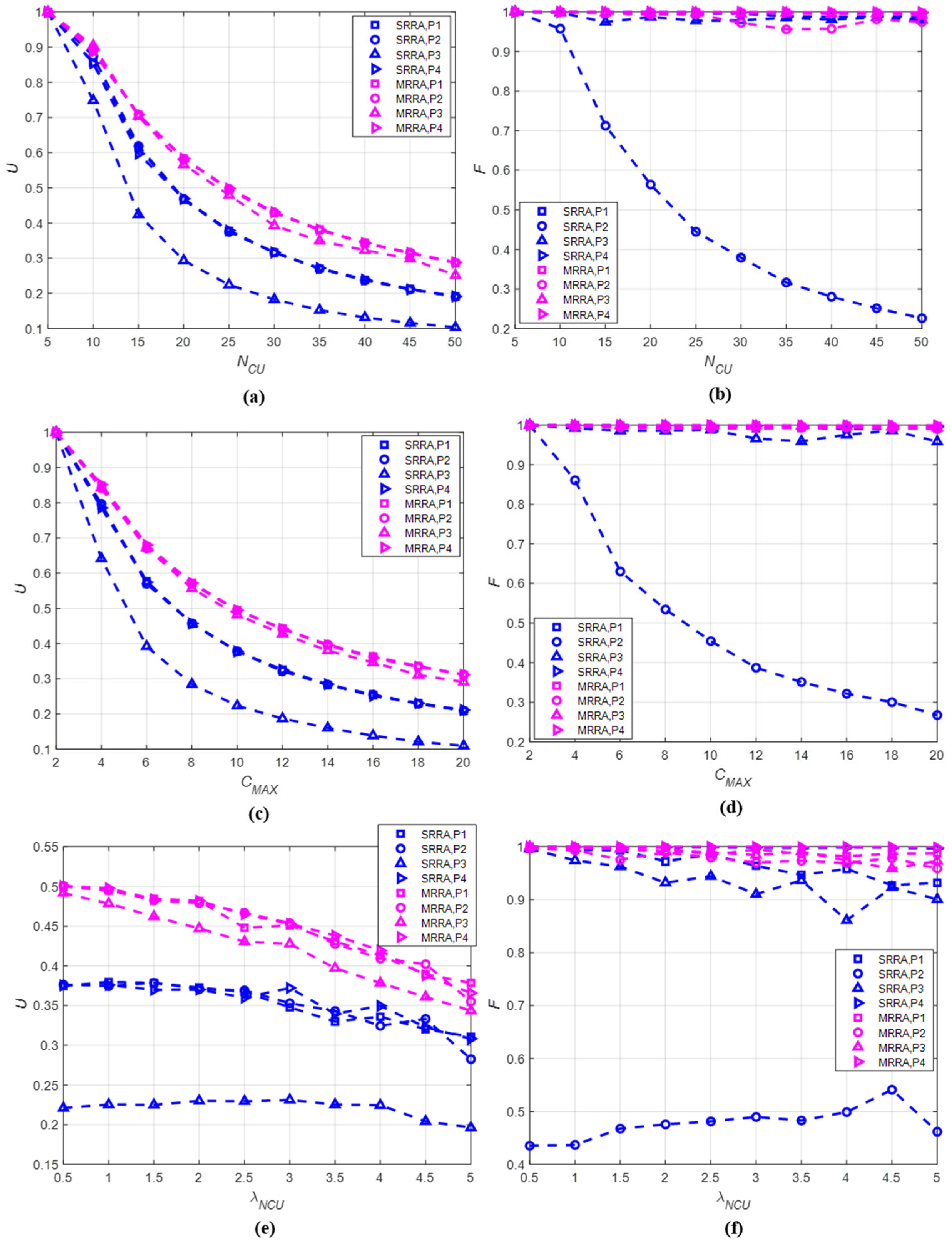
5.3.3. Results
- As shown in Figure 6a, the channel allocation rate of the MRRA was higher than that of the SRRA. This implies that allocating a data channel to a CU one by one can improve the channel allocation rate further;
- As the increased, the channel allocation rate decreased. This was because the number of data channels to be allocated decreased as the number of CUs increased;
- The channel allocation rates of the P1, P2, and P4 orders, except for the P3 order (high QoS-based allocation order), had unremarkable differences. In particular, the SRRA-P3 order resulted in the lowest channel allocation rate;
- As illustrated in Figure 6b, except for the SRRA-P2 order, the fairness index of all pairs was 0.9 or higher. This results from the fact that a CU with high priority can continuously obtain as many data channels as its QoS when the P2 order is applied.
- As for Case 1, the MRRA could guarantee a higher channel allocation rate than the SRRA in Case 2. In addition, the SRRA-P3 order still showed the worst channel allocation rate among all pairs as shown in Figure 6c;
- The increment of caused an increase in the number of data channels required by a CU. This result was the same as that in Case 1. Accordingly, when increased, the channel allocation rate inevitably decreased, regardless of the allocation orders;
- As shown in Figure 6d, the fairness index of Case 2 was also the same as that in Case 1. This resulted in a fairness index of 0.9 or higher in all cases, except for the SRRA-P2 order.
- In this case, the MRRA also guaranteed a higher channel allocation rate than SRRA, regardless of the allocation orders as illustrated in Figure 6e. The SRRA-P3 order resulted in the lowest channel allocation rate;
- As increased, the number of NCUs occurring at each data channel also increased. A data channel where an NCU exists is considered unusable, such that the number of available data channels decreases. Accordingly, the channel allocation rate was inversely proportional to ;
- The fairness index result of Case 3 was also similar to that of Cases 1 and 2, as shown in Figure 6f. However, if many NCUs occur in one data channel due to the increase in , the fairness index of the P3 order, in addition to the P2 order, dropped to 0.9 or lower in the SRRA. From this result, the P2 and P3 orders with the SRRA were inefficient in cases where the number of available data channels decreased due to the increase in .
- By considering the simulation results, we can conclude the analysis as follows:
- It was shown that the performance of all RA allocation order pairs were affected by the given conditions such as , , and . While could not be modified due to the randomness of the activity of an NCU, and were adjustable as network parameters. Thus, the values of and could be determined to satisfy the target performance;
- The MRRA is more appropriate than the SRRA due to the fact of its higher channel allocation rate and fairness index;
- All allocation orders showed unremarkable performance differences when they were applied to the MRRA. However, the SRRA-P2 order resulted in the worst performance in terms of the channel allocation rate and the fairness index;
- From the simulation results, the P1 (random ordering) and P4 (low-channel allocation rate-based priority) allocation orders with the MRRA are preferred for the resource allocation of the UCSS protocol.
6. Conclusions
Funding
Institutional Review Board Statement
Informed Consent Statement
Data Availability Statement
Conflicts of Interest
Nomenclature
| The length of a frame | |
| The length of a sensing sub-frame | |
| The length of a non-sensing sub-frame | |
| The ratio of a sensing sub-frame to a non-sensing sub-frame () | |
| The index of a frame () | |
| The start time of the frame | |
| The midpoint of time of the frame, which is the same as the end time of a sensing sub-frame of the frame | |
| The end time of the frame | |
| The number of CUs | |
| The index of a CU () | |
| The number of data channels | |
| The index of a data channel () | |
| The signal strength detected by CU at the data channel and the frame | |
| The threshold of signal strength | |
| The state of the data channel detected by CU at the frame | |
| The maximum of required data channels of a CU | |
| The number of required data channels of CU at the frame corresponding to its QoS, | |
| The number of data channels assigned to CU at the frame | |
| The set of available data channels for CU at the frame that are not occupied by its neighboring NCUs | |
| The number of remaining data channels while a central entity executes resource allocation procedures | |
| The set of CUs that does not finish their resource allocation | |
| The set of CUs allocated to each data channel | |
| The channel allocation rate of CU at the frame | |
| The set of the channel allocation rate of all CUs, |
References
- Singh, S.; Crispo, M.; Bousquet, J.F.; Aljendi, S. A Janus compatible software-defined underwater acoustic multiple-input multiple-output modem. Int. J. Distrib. Sens. Netw. 2021, 17, 1–13. [Google Scholar] [CrossRef]
- Gazi, F.; Misra, S.; Ahmed, N.; Mukherjee, A.; Kumar, N. UnRest: Underwater reliable acoustic communication for multimedia. In Proceedings of the the IEEE Global Communications Conference, Taipei, Taiwan, 7–11 December 2020. [Google Scholar]
- Ahmad, A.M.; Barbeau, M.; Garcia-Alfaro, J. Doppler effect in the underwater acoustic ultra low frequency band. Mob. Netw. Appl. 2018, 23, 1282–1292. [Google Scholar] [CrossRef]
- Li, X.; Ding, H.; Fang, Y.; Pan, M.; Li, P.; Huang, X.; Glisic, S. Collaborative spectrum trading and sharing for cognitive radio networks. In Handbook of Cognitive Radio; Springer Nature: Singapore, 2017; pp. 1–38. [Google Scholar]
- Murad, M.; Sheikh, A.; Manzoor, M.; Felemban, E.; Qaisar, S. A survey on current underwater acoustic sensor network application. Int. J. Comput. Theory Eng. 2015, 7, 51–56. [Google Scholar] [CrossRef] [Green Version]
- Alfouzan, F.A. Energy-efficient collision avoidance MAC protocols for underwater sensor networks: Survey and challenges. J. Mar. Sci. Eng. 2021, 9, 741. [Google Scholar] [CrossRef]
- Jiang, Z. Underwater acoustic network-Issues and solutions. Int. J. Intell. Control Syst. 2008, 13, 152–161. [Google Scholar]
- Yun, C.; Choi, S. A Study of Standardizing Frequencies Using Channel Raster for Underwater Wireless Acoustic Sensor Networks. Sensors 2021, 21, 5669. [Google Scholar] [CrossRef]
- Liu, J.; Wang, J.; Song, S.; Cui, J.; Wang, X.; Li, B. MMNET: A Multi-Modal Network Architecture for Underwater Networking. Electronics 2020, 9, 2186. [Google Scholar] [CrossRef]
- Schott, D.J.; Gabbrielli, A.; Xiong, W.; Fischer, G.; Höflinger, F.; Wendeberg, J.; Schindelhauer, C.; Rupitsch, S.J. Asynchronous Chirp Slope Keying for Underwater Acoustic Communication. Sensors 2021, 21, 3282. [Google Scholar] [CrossRef]
- Chen, Y.; Zhang, X.; Sun, X.; Tao, Y.; Xu, X. MF-HER: Marine mammal-friendly based high spectral-efficient routing for underwater acoustic sensor networks. IEEE Access 2020, 8, 198624–198636. [Google Scholar] [CrossRef]
- Guqhaiman, A.; Akanbi, O.; Aljaedi, A.; Chow, C.E. A survey on MAC protocol approaches for underwater wireless sensor networks. IEEE Sens. J. 2021, 21, 3916–3932. [Google Scholar] [CrossRef]
- Wei, L.; Guo, Y.; Cai, S. MAC protocol for underwater acoustic sensor network based on belied state space. EURASIP J. Wirel. Commun. Netw. 2018, 2018, 119. [Google Scholar] [CrossRef]
- Mishachandar, B.; Vairamuthu, S. An underwater cognitive acoustic network strategy for efficient spectrum utilization. Appl. Acoust. 2021, 175, 107861. [Google Scholar] [CrossRef]
- Song, H.C.; Hodgkiss, W.S. Efficient use of bandwidth for underwater acoustic communication. J. Acoust. Soc. Am. 2013, 134, 905–908. [Google Scholar] [CrossRef]
- Wang, Q.; Dai, H.-N.; Cheang, C.F.; Wang, H. Link Connectivity and Coverage of Underwater Cognitive Acoustic Networks under Spectrum Constraint. Sensors 2017, 17, 2839. [Google Scholar] [CrossRef] [Green Version]
- Luo, Y.; Pu, L.; Zuba, M.; Peng, Z.; Cui, J.H. Challenges and opportunities of underwater cognitive acoustic networks. IEEE Trans. Emerg. Top. Comput. 2014, 2, 198–211. [Google Scholar] [CrossRef]
- Bicen, A.O.; Sahin, A.B.; Akan, O.B. Spectrum-aware underwater networks: Cognitive acoustic communications. IEEE Veh. Tech. Mag. 2012, 7, 34–40. [Google Scholar] [CrossRef]
- Rai, A.; Sehgal, A.; Singal, T.L.; Agrawal, R. Spectrum sensing and allocation schemes for cognitive radio. In Machine Learning and Cognitive Computing for Mobile Communications and Wireless Networks; John Wiley Online Library: Hoboken, NJ, USA, 2020. [Google Scholar]
- Arjoune, Y.; Kaabouch, N. A Comprehensive Survey on Spectrum Sensing in Cognitive Radio Networks: Recent Advances, New Challenges, and Future Research Directions. Sensors 2019, 19, 126. [Google Scholar] [CrossRef] [PubMed] [Green Version]
- Singh, W.N.; Marchang, N. A review on spectrum allocation in cognitive radio networks. Int. J. Commun. Netw. Distrib. Syst. 2019, 23, 1–22. [Google Scholar]
- Eltom, H.; Kandeepan, S.; Evans, R.J.; Liang, Y.C.; Ristic, B. Statistical spectrum occupancy prediction for dynamic spectrum access: A classification. EURASIP J. Wirel. Commun. Netw. 2018, 2018, 29. [Google Scholar] [CrossRef] [Green Version]
- Piran, M.J.; Pham, Q.V.; Ialam, S.M.R.; Cho, S.; Bae, B.; Suh, D.Y.; Han, Z. Mutlimedia communication over cognitive radio networks from QoS/QoE perspective: A comprehensive survey. J. Netw. Comput. Appl. 2020, 171, 102759. [Google Scholar] [CrossRef]
- Li, X.; Guo, Y.; Fu, X.; Pan, M. Dolphins first: Dolphin-aware communications with multi-hop underwater cognitive acoustic networks. IEEE Trans. Wirel. Commun. 2017, 16, 2043–2056. [Google Scholar] [CrossRef]
- Luo, Y.; Mo, H.; Zhu, Y.; Peng, Z.; Cui, J.H. Receiver-initiated spectrum management for underwater cognitive acoustic network. IEEE Trans. Mob. Comput. 2017, 16, 198–212. [Google Scholar] [CrossRef]
- Wang, D.; Zhang, Y.; Hu, X.; Zhang, R.; Su, W.; Xie, Y. A dynamic spectrum decision algorithm for underwater cognitive acoustic networks. In Proceedings of the 11th ACM International Conference on Underwater Networks & Systems, Shanghai, China, 24–26 October 2016. [Google Scholar]
- Baldo, N.; Casari, P.; Zorzi, M. Cognitive spectrum access for underwater acoustic communications. In Proceedings of the 2008 IEEE International Conference on Communications Workshops, Beijing, China, 25–27 May 2008. [Google Scholar]
- Luo, Y.; Pu, Z.; Peng, J.; Cui, J. Dynamic control channel MAC for underwater cognitive acoustic networks. In Proceedings of the 35th Annual IEEE International Conference on Computer Communications, San Francisco, CA, USA, 10–14 April 2016. [Google Scholar]
- Pottier, A.; Socheleau, F.-X.; Laot, C. Robust noncooperative spectrum sharing game in underwater acoustic interference channels. IEEE J. Ocean. Eng. 2017, 42, 1019–1034. [Google Scholar] [CrossRef] [Green Version]
- Jin, Z.; Li, Y.; Luo, Y.; Yang, Q. Spectrum allocation and protocol based on cognitive acoustic technique in underwater networks. Trans. Tianjin Univ. 2016, 22, 339–344. [Google Scholar] [CrossRef]
- Wu, Y.; Li, Y.; Yao, Q. Adaptive energy efficiency maximization for cognitive underwater acoustic network under spectrum sensing errors and CSI uncertainties. Wirel. Commun. Mob. Comut. 2019, 2019, 2875136. [Google Scholar] [CrossRef]
- Le, A.-M.; Kim, D.-S. Joint channel and power allocation for underwater cognitive acoustic networks. In Proceedings of the 2014 International Conference on Advanced Technologies for Communications (ATC 2014), Hanoi, Vietnam, 15–17 October 2014. [Google Scholar]
- Yan, L.; Li, X.; Ma, K.; Yan, J.; Han, S. Joint relay selection and power allocation in underwater cognitive acoustic cooperative system with limited feedback. In Proceedings of the 2016 IEEE 83rd Vehicular Technology Conference (VTC Spring), Nanjing, China, 15–18 May 2016. [Google Scholar]
- Yan, L.; Li, R.; Li, X.; Wang, J. Joint relay selection and power allocation with trust parameter in an underwater cognitive acoustic cooperative system. Ad-Hoc Sens. Wirel. Netw. 2020, 49, 1–17. [Google Scholar]
- Liu, X.; Jia, M. Cooperative spectrum sensing and data transmission optimization for multichannel cognitive sonar communication network. EURASIP J. Wirel. Commun. Netw. 2017, 2017, 171. [Google Scholar] [CrossRef] [Green Version]
- Mokhtar, R.; Saeed, R.; Khatun, S. Spectrum sharing for cognitive radio and advanced spectrum management. In Proceedings of the SETIT 2009, 5th International Conference: Sciences of Electronic, Technologies of Information and Telecommunications, Hammanet, Tunisia, 22–26 March 2009. [Google Scholar]
- Amin, S.I.; Tarek, M.S.; Sherine, M.A.; Hussein, S.E. Mapping spectrum sharing techniques with cognitive radio applications. Int. J. Appl. Innov. Eng. Manag. 2016, 5, 109–122. [Google Scholar]
- Kour, H.; Jha, R.K.; Jain, S. A comprehensive survey on spectrum sharing: Architecture, energy efficiency and security issues. J. Netw. Compu. Appl. 2018, 103, 29–57. [Google Scholar] [CrossRef]
- Alfourzan, I.; Woodward, M.E. Load balancing—Node transfer trade-off in reconfigurable WDM networks. IEE Proc. Commun. 2006, 153, 469–474. [Google Scholar] [CrossRef]


| Item | CRN | UCAN |
|---|---|---|
| Medium | Radio frequency band supporting a higher bandwidth and a faster data rate than acoustic frequency | Acoustic frequency band (a few hundred kHz to a few hundred kHz) with a narrow bandwidth (less than a few hundred kHz) and long propagation delay (the average propagation velocity is roughly 1500 mps). |
| Channel model | Possible to predict the channel model and the introduction of several channel models | Hard to predict the channel model and the severe multipath environment |
| Channel plan | Strict channel plan according to frequencies, including center frequency, channel number, and bandwidth | Open spectrum where no user has an exclusive right and, thus, the overlapped use of frequencies is inevitable |
| Interferer | Unlicensed users who follow the channel plan | Natural and artificial interferers of which their activities are unpredictable |
| Signals | Standardized signals including modulation, coding scheme (MCS), and message format | Nonstandardized signals that are undecodable and uninterpretable |
Publisher’s Note: MDPI stays neutral with regard to jurisdictional claims in published maps and institutional affiliations. |
© 2022 by the author. Licensee MDPI, Basel, Switzerland. This article is an open access article distributed under the terms and conditions of the Creative Commons Attribution (CC BY) license (https://creativecommons.org/licenses/by/4.0/).
Share and Cite
Yun, C. An Underwater Cooperative Spectrum Sharing Protocol for a Centralized Underwater Cognitive Acoustic Network. Sensors 2022, 22, 5754. https://doi.org/10.3390/s22155754
Yun C. An Underwater Cooperative Spectrum Sharing Protocol for a Centralized Underwater Cognitive Acoustic Network. Sensors. 2022; 22(15):5754. https://doi.org/10.3390/s22155754
Chicago/Turabian StyleYun, Changho. 2022. "An Underwater Cooperative Spectrum Sharing Protocol for a Centralized Underwater Cognitive Acoustic Network" Sensors 22, no. 15: 5754. https://doi.org/10.3390/s22155754
APA StyleYun, C. (2022). An Underwater Cooperative Spectrum Sharing Protocol for a Centralized Underwater Cognitive Acoustic Network. Sensors, 22(15), 5754. https://doi.org/10.3390/s22155754