
A Compact Four-Port MIMO Antenna for UWB Applications


Abstract
:1. Introduction
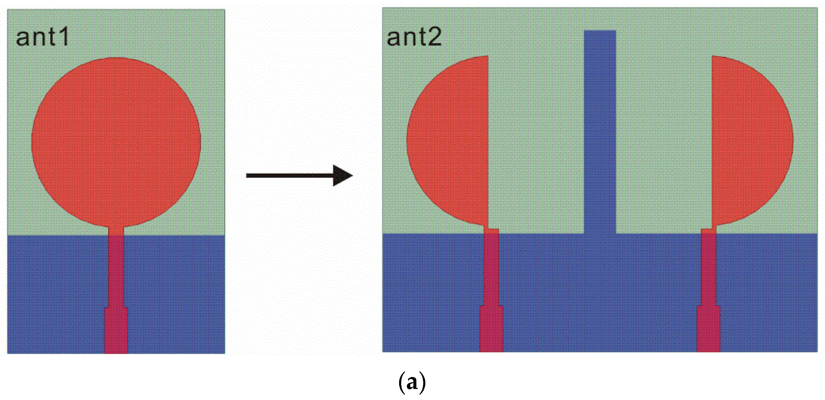
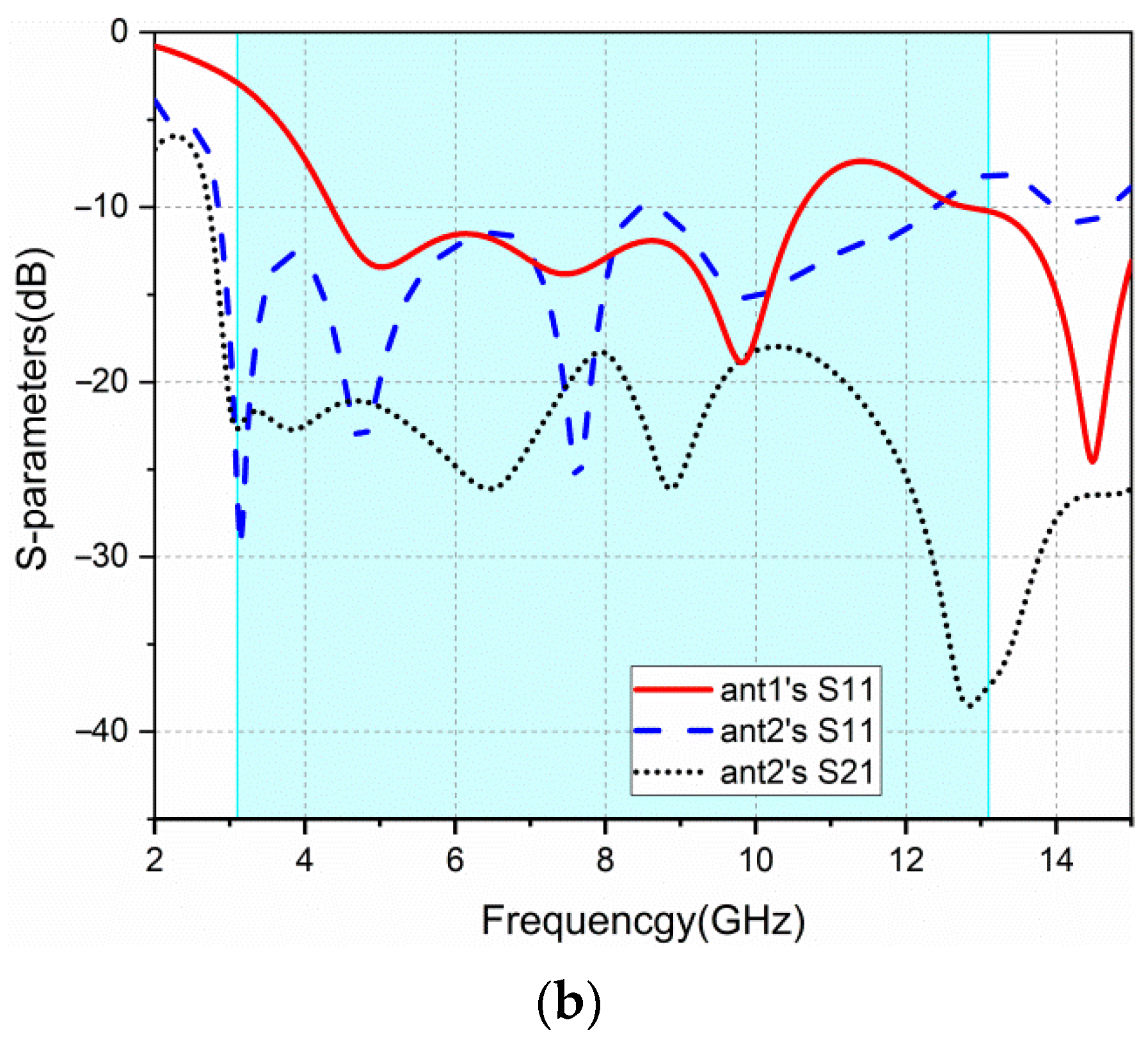
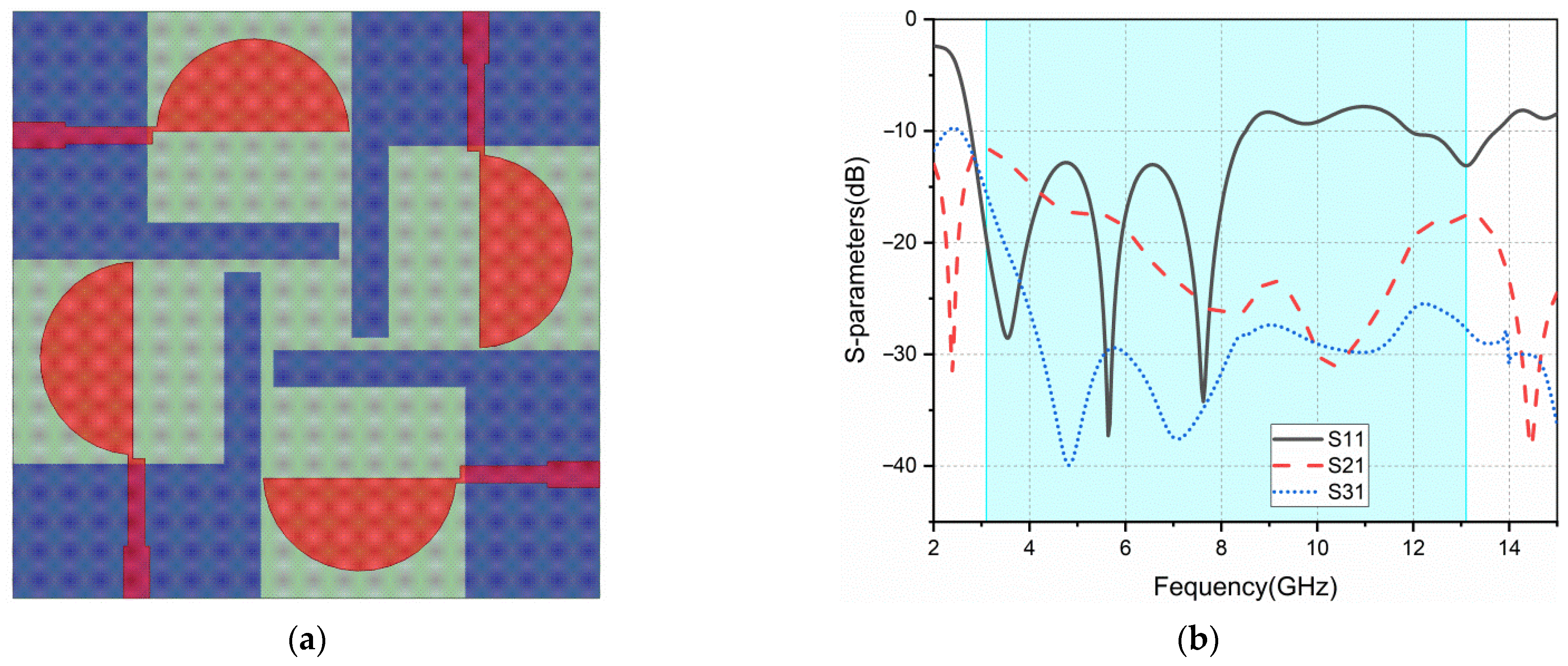
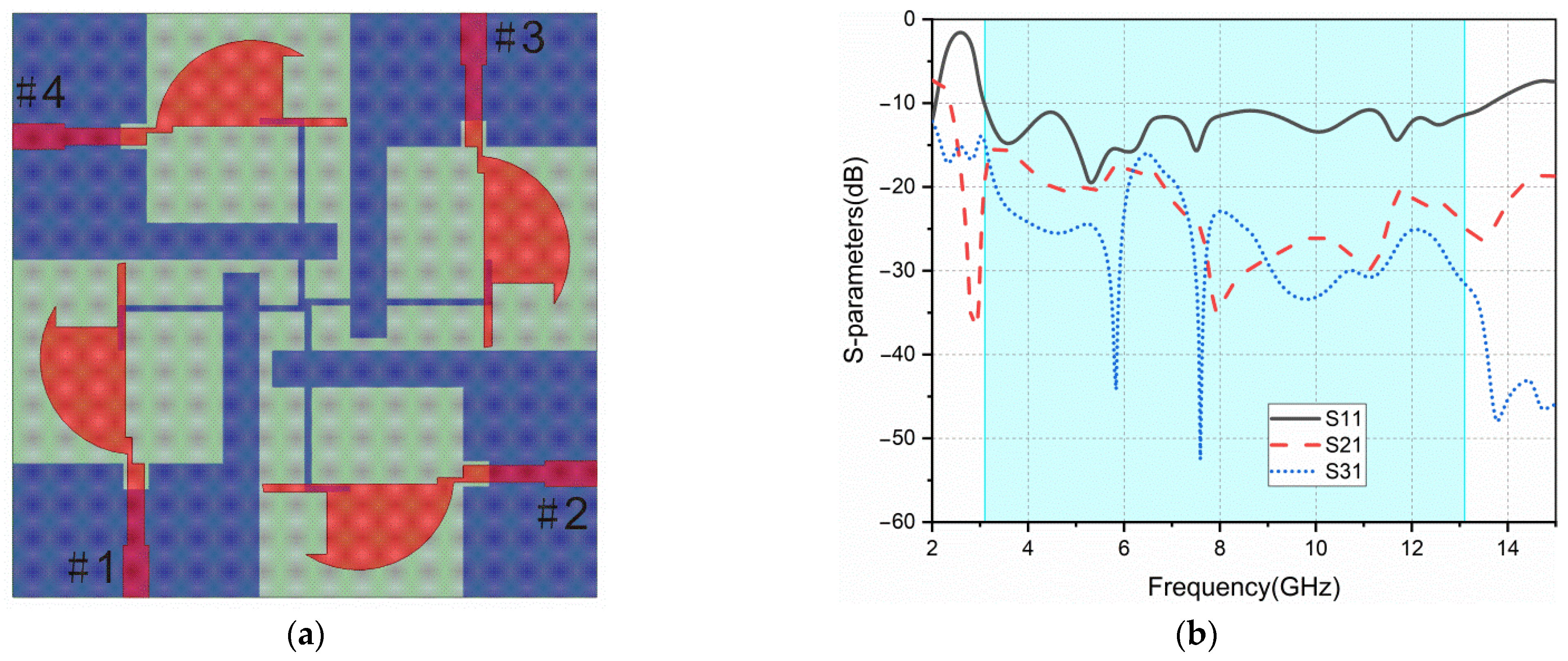
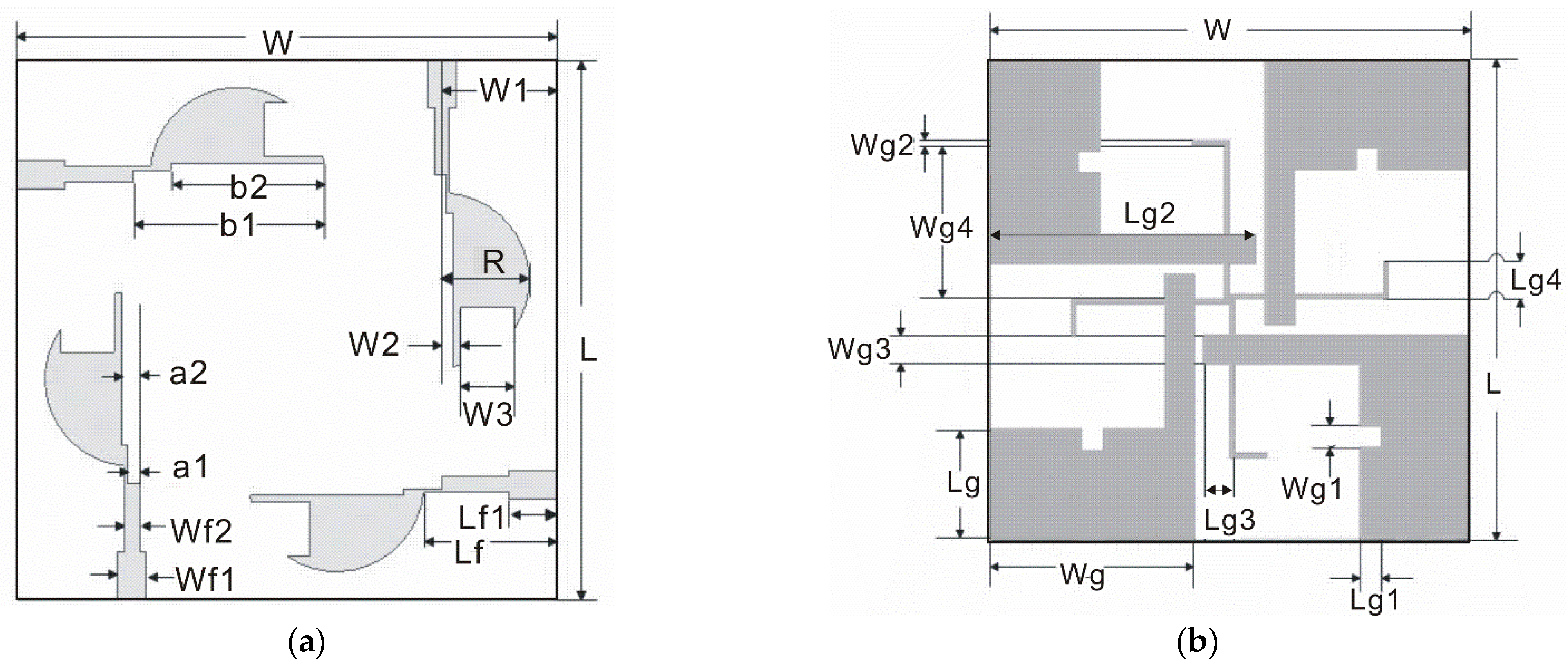
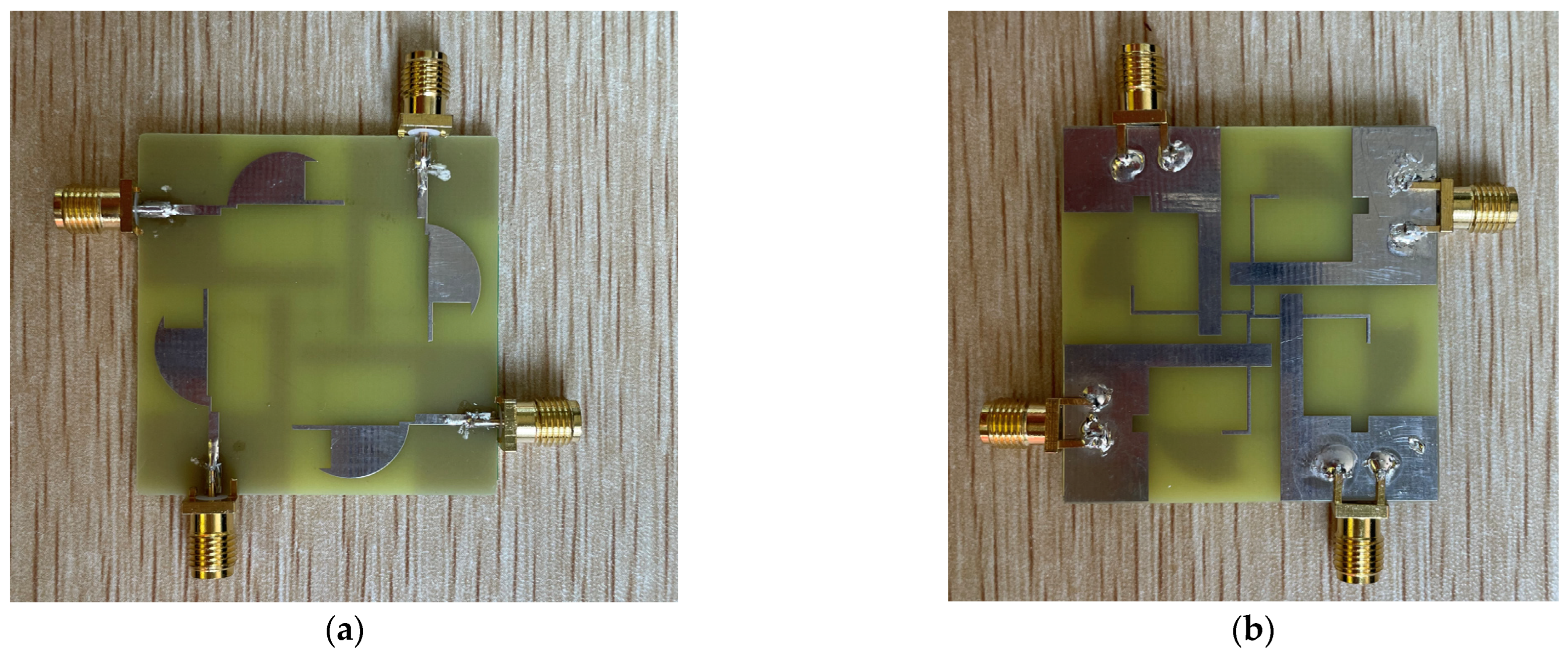
2. Antenna Design
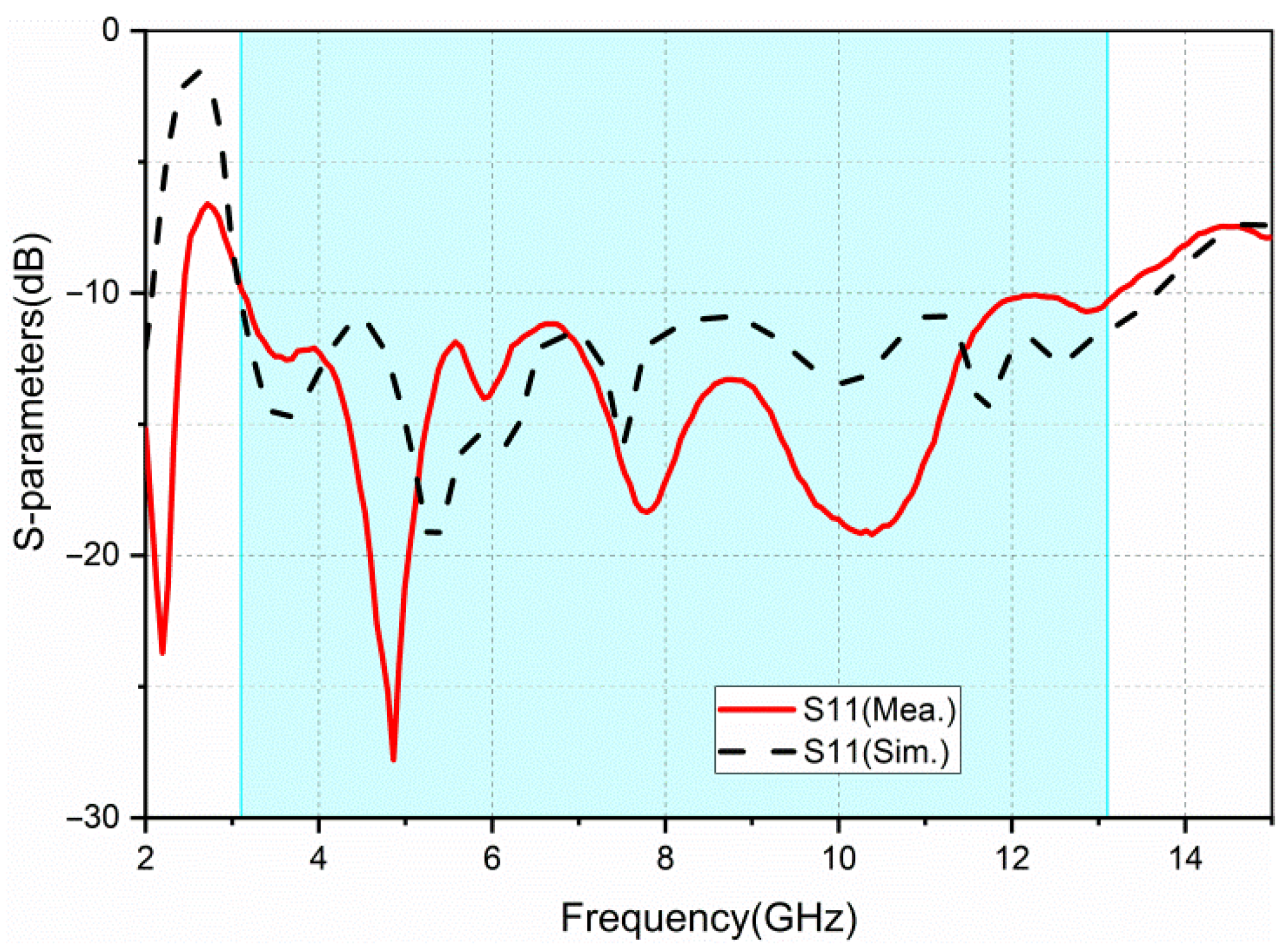
3. Results and Discussion
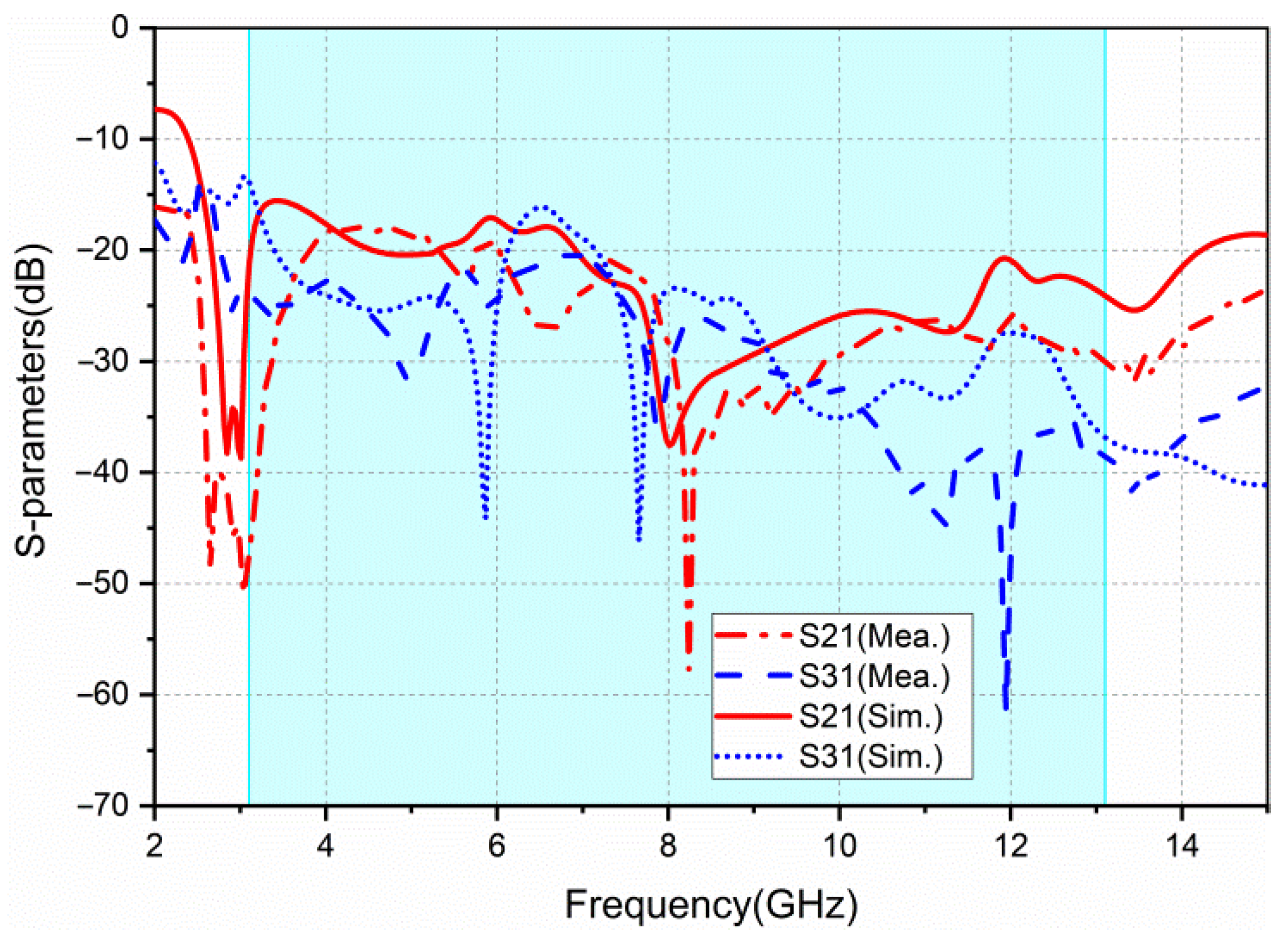
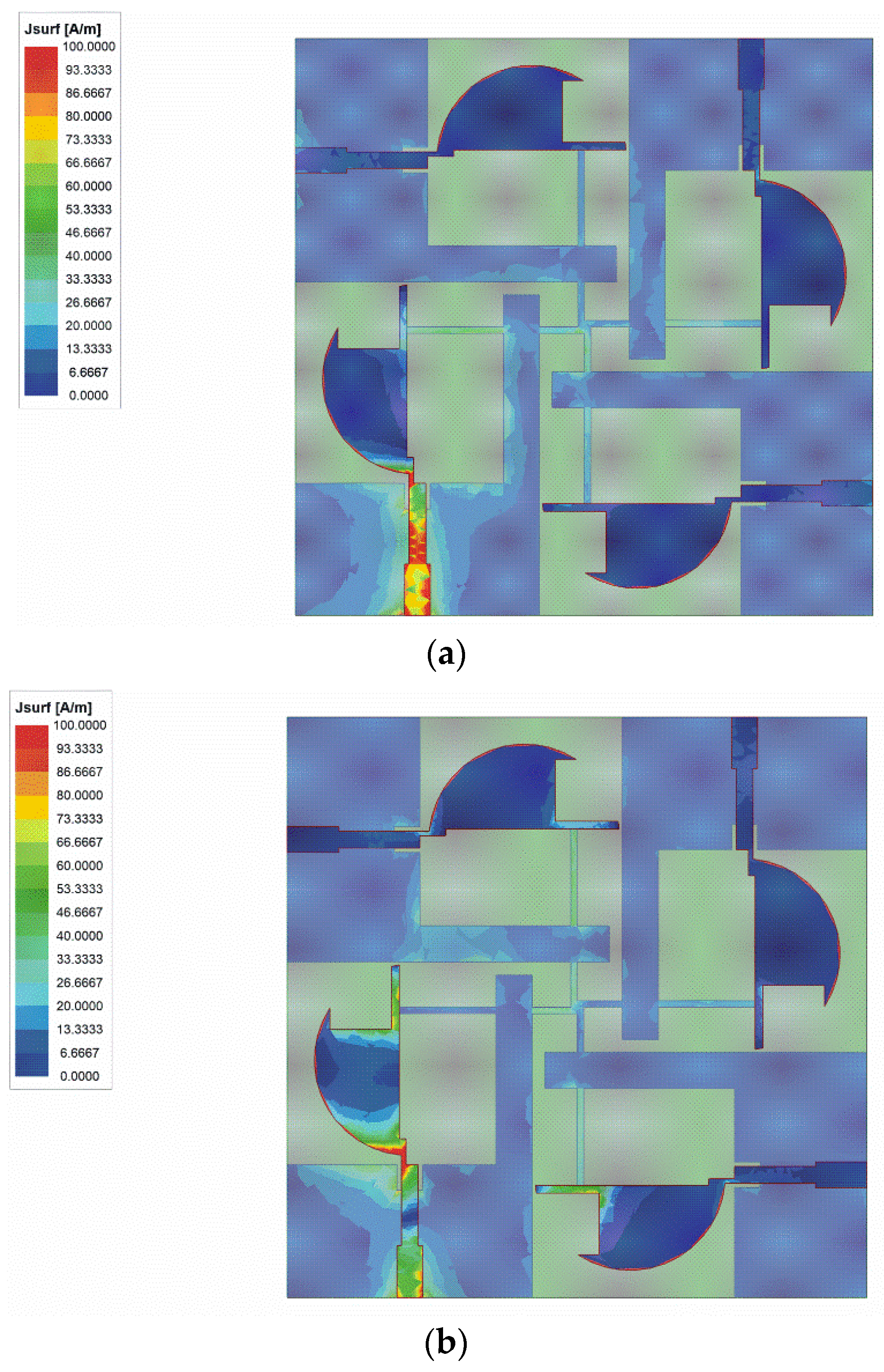
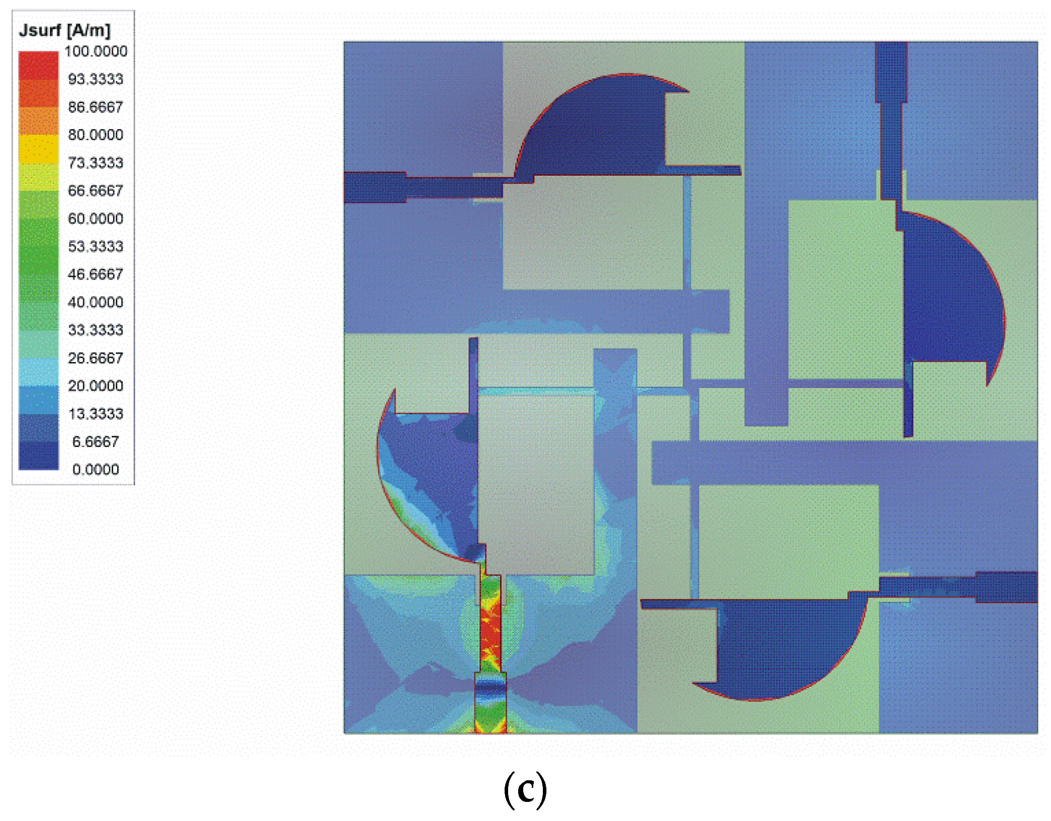
3.1. S-Parameters
3.2. Diversity Performance
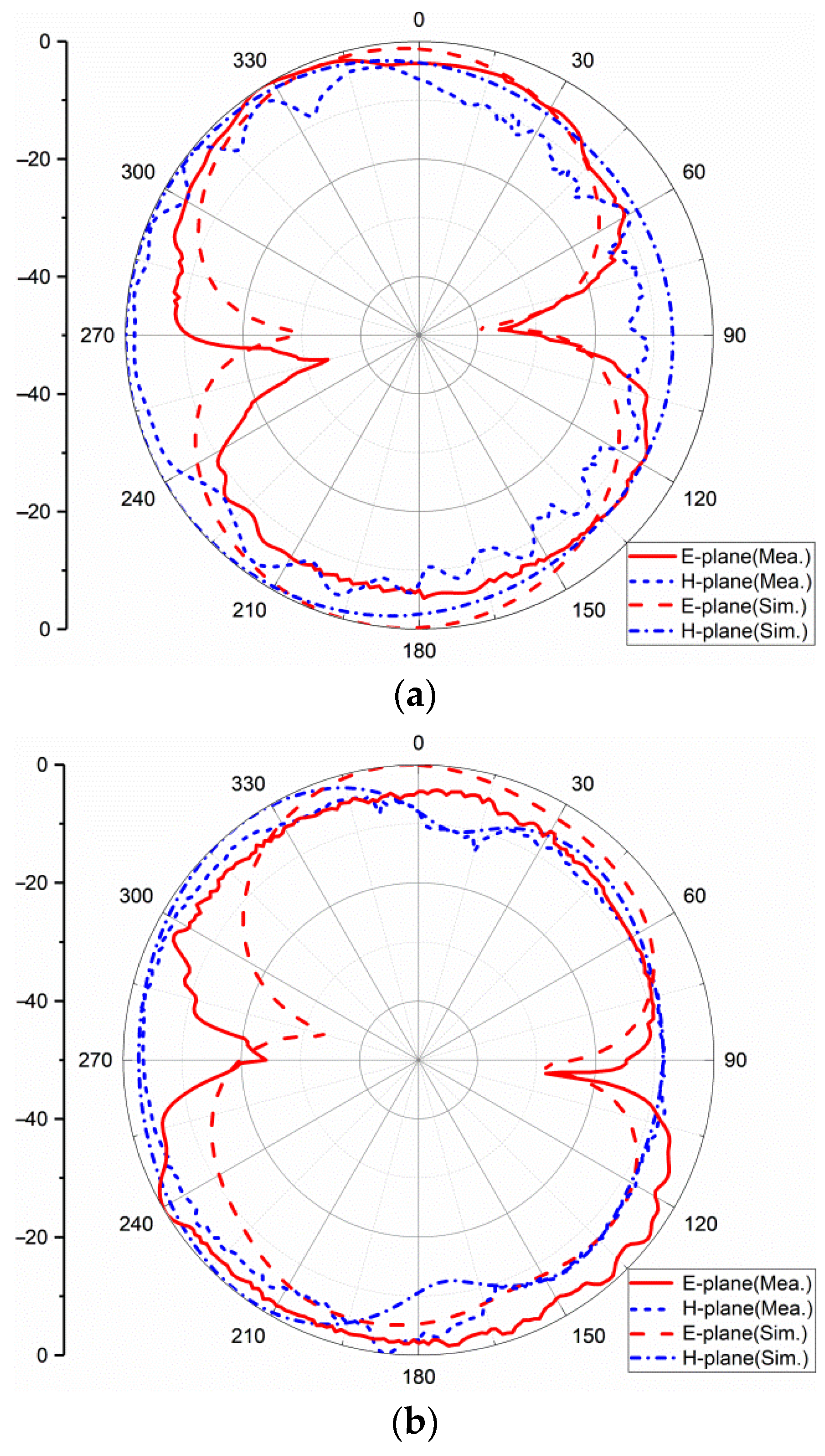
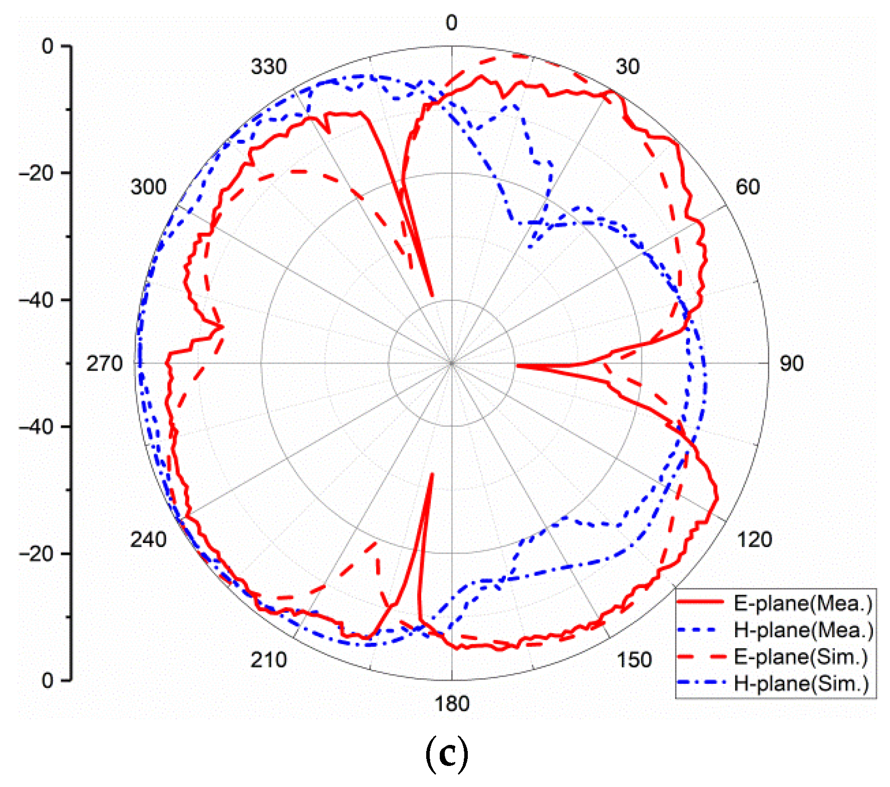
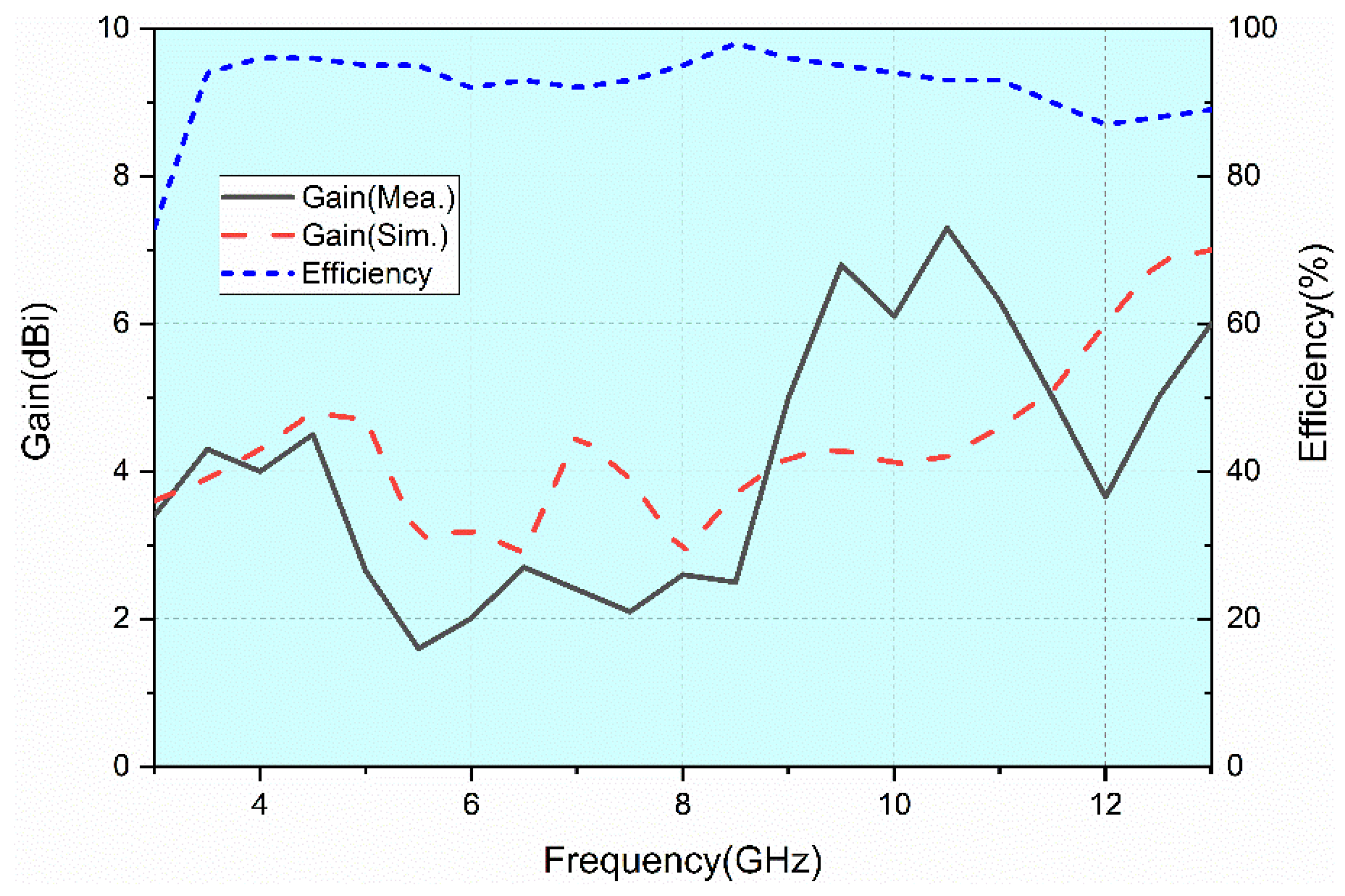
3.3. Radiation Pattern, Gain, and Efficiency
4. Conclusions
Author Contributions
Funding
Institutional Review Board Statement
Informed Consent Statement
Data Availability Statement
Conflicts of Interest
References
- Srivastava, N.; Rao, P.K.; Mishra, R. Decoupling Function for UWB MIMO Antenna to Enhance Bandwidth with Neutralization Line. In Proceedings of the 2019 IEEE 5th International Conference for Convergence in Technology (I2CT), Bombay, India, 29–31 March 2019; pp. 1–3. [Google Scholar] [CrossRef]
- Khan, M.S.; Capobianco, A.D.; Asif, S.; Iftikhar, A.; Braaten, B.D. A 4 element compact Ultra-Wideband MIMO antenna array. In Proceedings of the IEEE International Symposium on Antennas & Propagation & USNC/URSI National Radio Science Meeting, Vancouver, BC, Canada, 19–24 July 2015. [Google Scholar]
- Zhang, K.; Li, J.; Zhai, H.; Wang, Z.; Zeng, Y. UWB-MIMO antenna decoupling based on a wideband parasitic unit structure. In Proceedings of the 2020 International Conference on Microwave and Millimeter Wave Technology (ICMMT), Shanghai, China, 20–23 September 2020; pp. 1–3. [Google Scholar] [CrossRef]
- Pandit, S.; Mohan, A.; Ray, P.; Rana, B. Compact Four-Element MIMO Antenna Using DGS for WLAN Applications. In Proceedings of the 2018 International Symposium on Antennas and Propagation (ISAP), Busan, Korea, 23–26 October 2018; pp. 1–2. [Google Scholar]
- Zhang, S.; Ying, Z.; Xiong, J.; He, S. Ultrawideband MIMO/Diversity Antennas with a Tree-Like Structure to Enhance Wideband Isolation. IEEE Antennas Wirel. Propag. Lett. 2009, 8, 1279–1282. [Google Scholar] [CrossRef]
- Khan, A.; Bashir, S.; Ghafoor, S.; Qureshi, K.K. Mutual Coupling Reduction Using Ground Stub and EBG in a Compact Wideband MIMO-Antenna. IEEE Access 2021, 9, 40972–40979. [Google Scholar] [CrossRef]
- Zhou, W.; Li, Y. A Taichi-Bagua-like Metamaterial Covering High Isolation MIMO for 5G Application. In Proceedings of the 2021 IEEE 4th International Conference on Electronic Information and Communication Technology (ICEICT), Xi’an, China, 18–20 August 2021; pp. 948–949. [Google Scholar] [CrossRef]
- Al-Gburi, A.J.A.; Ibrahim, I.M.; Zakaria, Z.; Abdulhameed, M.K.; Saeidi, T. Enhancing Gain for UWB Antennas Using FSS: A Systematic Review. Mathematics 2021, 9, 3301. [Google Scholar] [CrossRef]
- De Sabata, A.; Matekovits, L.; Buta, A.; Dassano, G.; Silaghi, A. Frequency Selective Surface for Ultra-Wide Band Filtering and Shielding. Sensors 2022, 22, 1896. [Google Scholar] [CrossRef] [PubMed]
- Gurjar, R.; Upadhyay, D.K.; Kanaujia, B.K. Compact four-element 8-shaped self-affine fractal UWB MIMO antenna. In Proceedings of the 2018 3rd International Conference on Microwave and Photonics (ICMAP), Dhanbad, India, 9–11 February 2018. [Google Scholar]
- Ellatif, W.A.; Aziz, D.; Mahmoud, R. A 4-elements performance analysis of compact UWB antenna for MIMO-OFDM systems. In Proceedings of the IEEE International Conference on Wireless for Space and Extreme Environments (WiSEE) 2016, Aachen, Germany, 26–28 September 2016. [Google Scholar]
- Mathur, R.; Dwari, S. A compact 4-port UWB-MIMO/diversity antenna for WPAN application. In Proceedings of the 3rd International Conference on Microwave and Photonics (ICMAP 2018), Dhanbad, India, 9–11 February 2018. [Google Scholar]
- Chen, Z.; Zhou, W.; Hong, J. A Miniaturized MIMO Antenna with Triple Band-Notched Characteristics for UWB Applications. IEEE Access 2021, 9, 63646–63655. [Google Scholar] [CrossRef]
- Tripathi, S.; Mohan, A.; Yadav, S. A Compact Koch Fractal UWB MIMO Antenna with WLAN Band-Rejection. IEEE Antennas Wirel. Propag. Lett. 2015, 14, 1565–1568. [Google Scholar] [CrossRef]
- Ahmad, S.; Khan, S.; Manzoor, B.; Soruri, M.; Alibakhshikenari, M.; Dalarsson, M.; Falcone, F. A Compact CPW-Fed Ultra-Wideband Multi-Input-Multi-Output (MIMO) Antenna for Wireless Communication Networks. IEEE Access 2022, 10, 25278–25289. [Google Scholar] [CrossRef]
- Radhi, A.H.; Nilavalan, R.; Wang, Y.; Al-Raweshidy, H.S.; Eltokhy, A.A.; AbAziz, N. Mutual coupling reduction with a wideband planar decoupling structure for UWB-MIMO antennas. Int. J. Microw. Wirel. Technol. 2018, 10, 1143–1154. [Google Scholar] [CrossRef] [Green Version]
- Kayabasi, A.; Toktas, A.; Yigit, E.; Sabanci, K. Triangular quad-port multi-polarized UWB MIMO antenna with enhanced isolation using neutralization ring. AEU Int. J. Electron. Commun. 2018, 85, 47–53. [Google Scholar] [CrossRef]
- Khac, K.N.; Bao, P.; Ngoc, C.D. Design of Compact 4 × 4 UWB-MIMO Antenna with WLAN Band Rejection. Int. J. Antennas Propag. 2014, 2014, 539094. [Google Scholar]
- Gómez-Villanueva, R.; Jardón-Aguilar, H. Compact UWB Uniplanar Four-Port MIMO Antenna Array with Rejecting Band. IEEE Antennas Wirel. Propag. Lett. 2019, 18, 2543–2547. [Google Scholar] [CrossRef]
- Raheja, D.K.; Kanaujia, B.K.; Kumar, S. Compact four-port MIMO antenna on slotted-edge substrate with dual-band rejection characteristics. Int. J. RF Microw. Comput.-Aided Eng. 2019, 29, e21756. [Google Scholar] [CrossRef]
- Kumar, S.; Lee, G.; Kim, D.; Mohyuddin, W.; Choi, H.; Kim, K. A compact four-port UWB MIMO antenna with connected ground and wide axial ratio bandwidth. Int. J. Microw. Wirel. Technol. 2020, 12, 75–85. [Google Scholar] [CrossRef]


| Dimension | Value (mm) | Dimension | Value (mm) | Dimension | Value (mm) |
|---|---|---|---|---|---|
| W | 45 | Wg4 | 14.4 | W2 | 1.4 |
| L | 45 | Lg | 10.3 | W3 | 4.8 |
| H | 1.6 | Lg1 | 2 | Lf | 11 |
| Wg | 19 | Lg2 | 22.2 | Lf1 | 4 |
| Wg1 | 2 | Lg3 | 2.5 | Wf1 | 2 |
| Wg2 | 0.5 | Lg4 | 3.5 | Wf2 | 1.3 |
| Wg3 | 2.8 | W1 | 9.5 | a1 | 0.95 |
| b1 | 15.5 | a2 | 1.45 | b2 | 13.5 |
| R | 7.4 |
| Ref. | Operating Frequency (GHz) | Bandwidth (%) | Size (λ0) 1 | Gain (dBi) | ECC | Iso. (dB) | Radiation Efficiency | Substrate | No. of Elements |
|---|---|---|---|---|---|---|---|---|---|
| [2] | 2.5~12 | 131% | 0.42λ0 × 0.33λ0 (50 mm × 39.8 mm) | N/A | <0.03 | >17 | N/A | TMM4 | 4 |
| [12] | 3~11 | 114% | 0.42λ0 × 0.42λ0 (42 mm × 42 mm) | 3.5 | <0.05 | >15 | >70% | FR4 | 4 |
| [15] | 3~11 | 114% | 0.6λ0 × 0.6λ0 (60 mm × 60 mm) | 3.4 | <0.02 | >20 | >68% | FR4 | 4 |
| [16] | 3.1~10.6 | 109% | 0.49λ0 × 0.97λ0 (47 mm × 93 mm) | 3.5 | <0.2 | >31 | >70% | FR4 | 2 |
| [17] | 3.1~17.3 | 139% | 0.78λ0 × 0.78λ0 (75.10 mm × 75.19 mm) | 5.5 | <0.1 | >13 | N/A | FR4 | 4 |
| [18] | 2.7~10.6 | 119% | 0.54λ0 × 0.54λ0 (60 mm × 60 mm) | 3.5 | <0.063 | >15 | N/A | FR4 | 4 |
| [19] | 3~13.2 | 126% | 0.383λ0 × 0.383λ0 (38.3 mm × 38.3 mm) | 4.1 | <0.02 | >17 | >72% | Taconic RF-45 | 4 |
| [20] | 3~13.5 | 127% | 0.58λ0 × 0.58λ0 (58 mm × 58 mm) | 2.9 | <0.008 | >22 | N/A | FR4 | 4 |
| [21] | 3.1~11 | 112% | 0.46λ0 × 0.46λ0 (45 mm × 45 mm) | 4.3 | <0.015 | >16 | N/A | FR4 | 4 |
| Pro. | 3.1~13.1 | 123% | 0.46λ0 × 0.46λ0 (45 mm × 45 mm) | 4.0 | <0.02 | >17 | >73% | FR4 | 4 |
Publisher’s Note: MDPI stays neutral with regard to jurisdictional claims in published maps and institutional affiliations. |
© 2022 by the authors. Licensee MDPI, Basel, Switzerland. This article is an open access article distributed under the terms and conditions of the Creative Commons Attribution (CC BY) license (https://creativecommons.org/licenses/by/4.0/).
Share and Cite
Wu, A.; Zhao, M.; Zhang, P.; Zhang, Z. A Compact Four-Port MIMO Antenna for UWB Applications. Sensors 2022, 22, 5788. https://doi.org/10.3390/s22155788
Wu A, Zhao M, Zhang P, Zhang Z. A Compact Four-Port MIMO Antenna for UWB Applications. Sensors. 2022; 22(15):5788. https://doi.org/10.3390/s22155788
Chicago/Turabian StyleWu, Aiting, Mingyang Zhao, Pengquan Zhang, and Zhonghai Zhang. 2022. "A Compact Four-Port MIMO Antenna for UWB Applications" Sensors 22, no. 15: 5788. https://doi.org/10.3390/s22155788