
Research on the Time Drift Stability of Differential Inductive Displacement Sensors with Frequency Output

 , , ,
, , ,
Abstract
:1. Introduction
2. Measurement and Different Operations for Digitalization
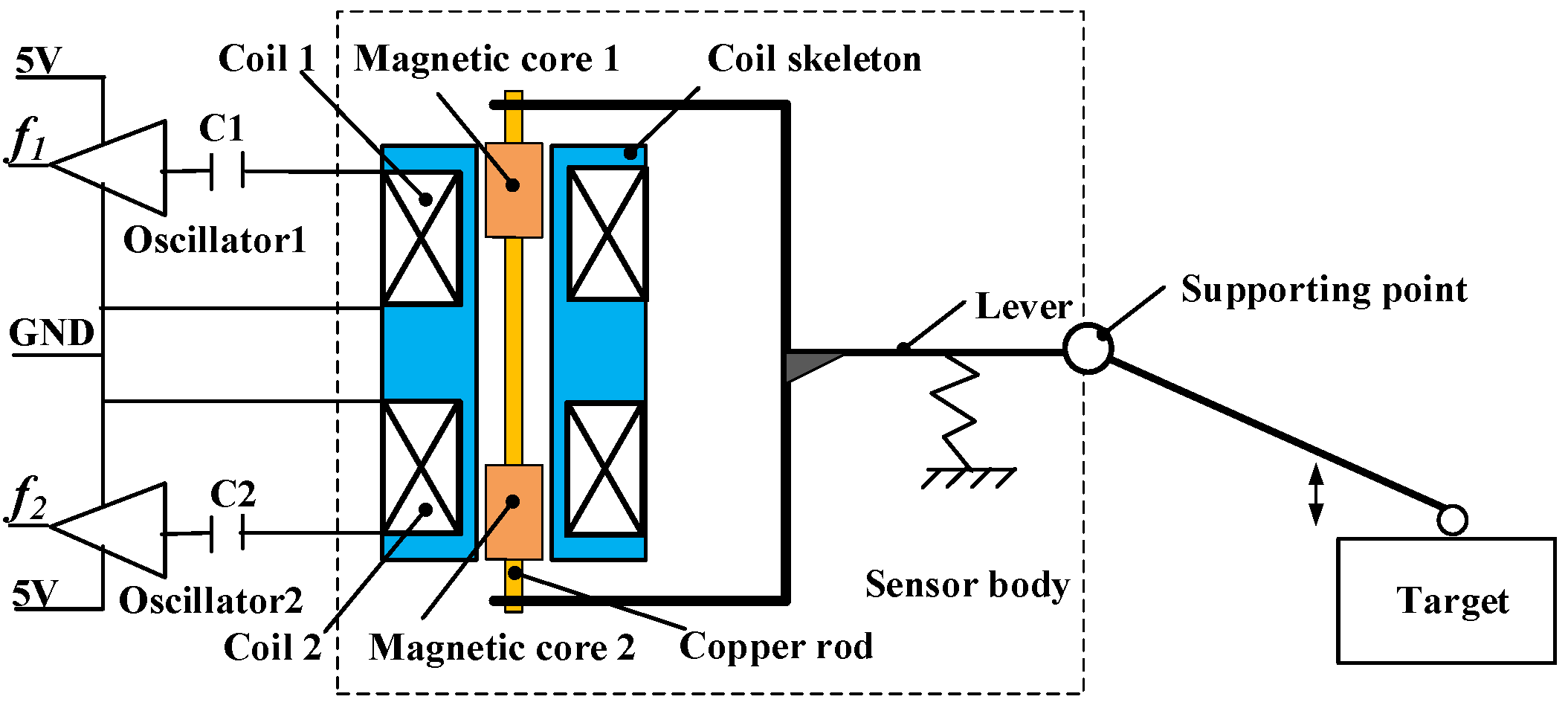
2.1. DIFOD Sensor Measurement Principle
2.2. Differential Operation Principles and Signal Conditioning
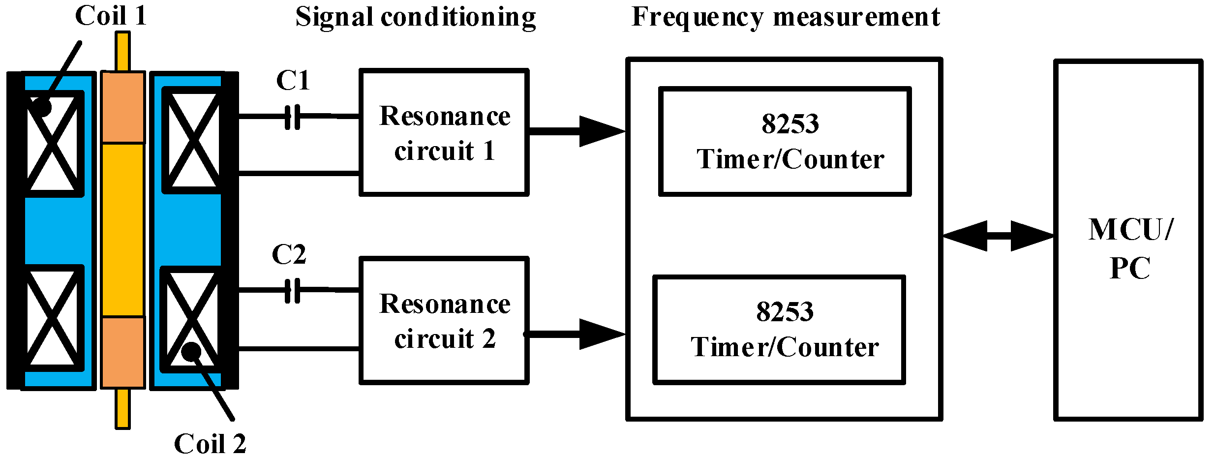
2.2.1. Signal Conditioning and Digitalization Based on Discrete Devices and PCB Boards
2.2.2. Signal Conditioning and Digitalization Based on LDC Chips
3. Experimental Rig and Testing
3.1. Experimental Setup and Different Displacement Sensors
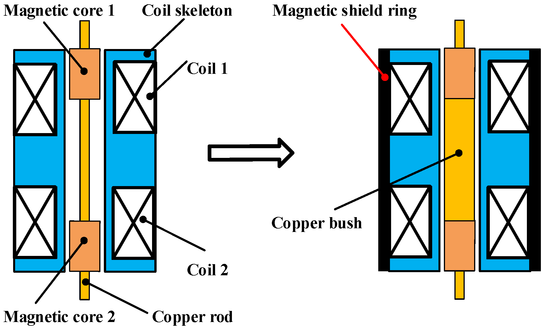
3.2. Sensors Probe Structure and Materials
3.3. Comparison Experiment of Different Signal Conditioning Circuits
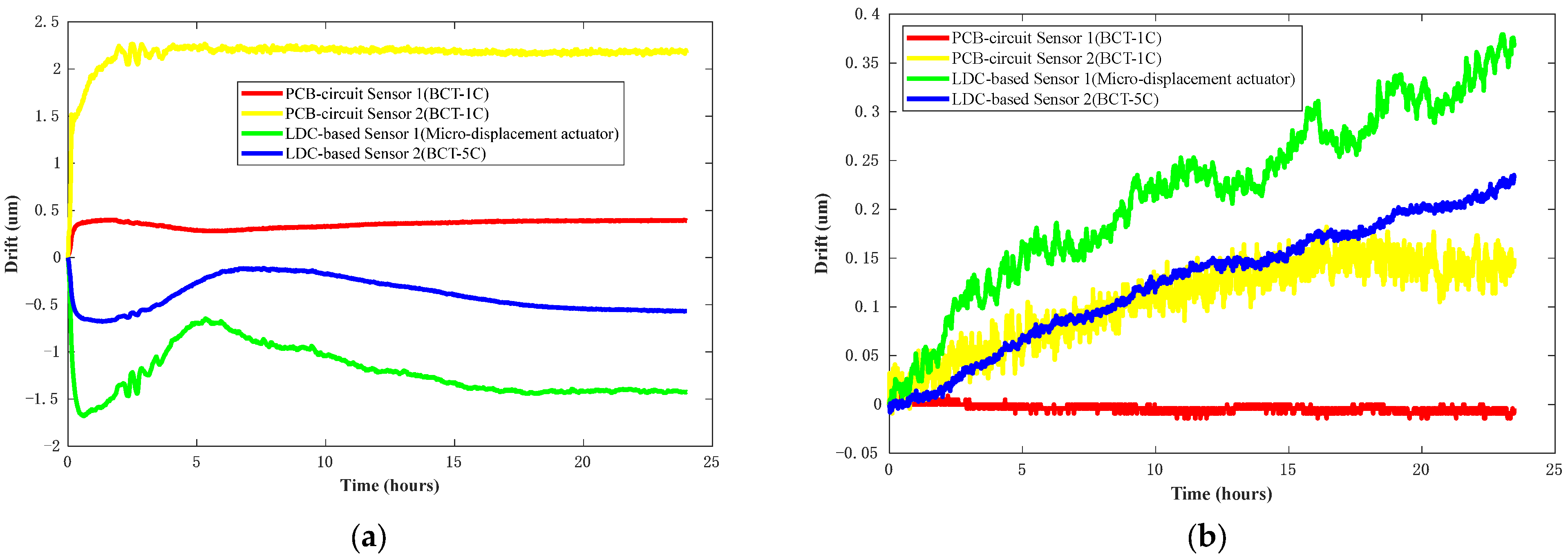
3.3.1. Time Drift or Stability under Controlled Temperatures
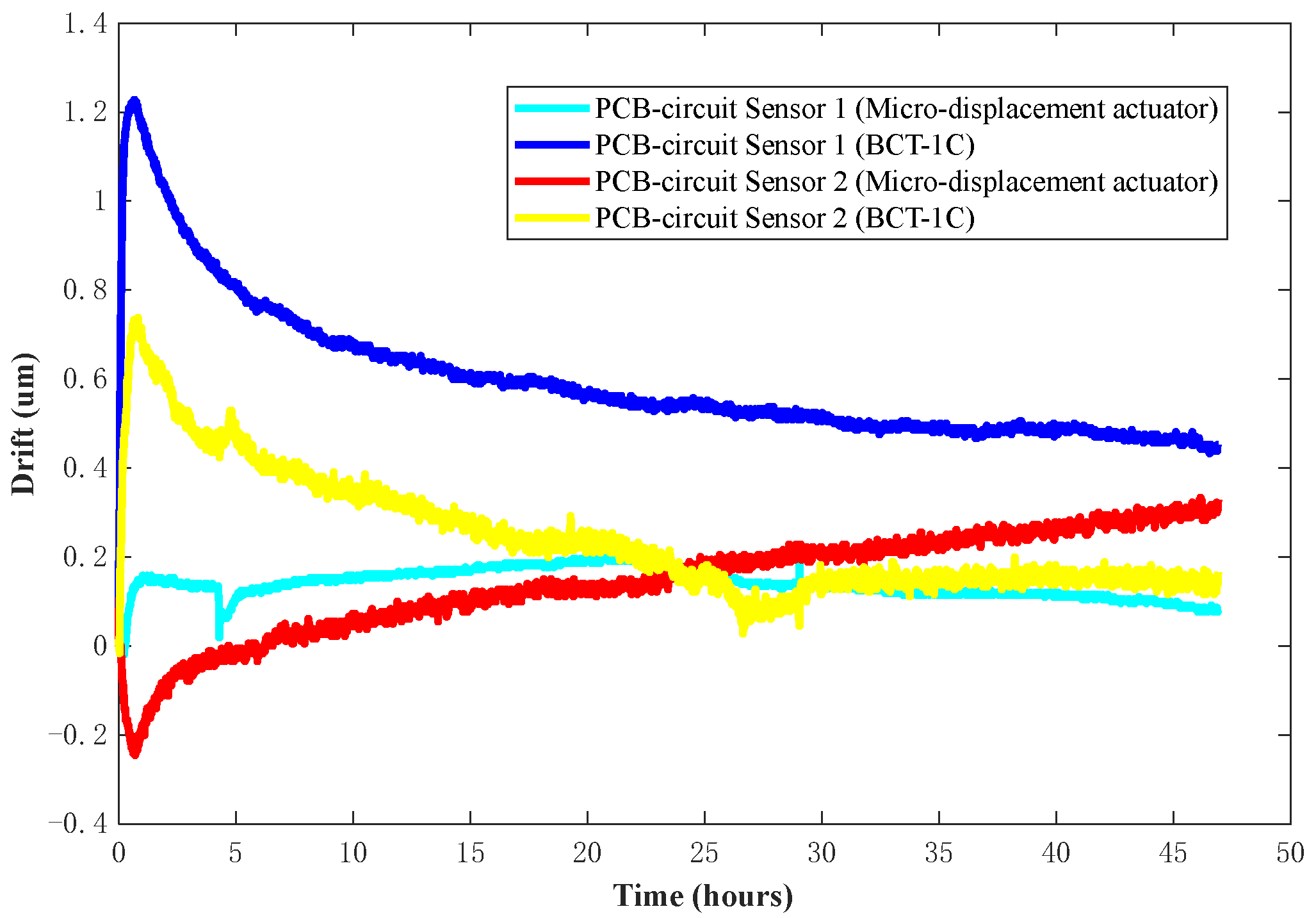
3.3.2. Comparison of Experiments with Different Sensor Fixtures and Different Sensors
4. Conclusions and Future Work
- (1)
- The magnetic field of the two coils is well isolated using the magnetic shield ring and the copper bush. They effectively reduce the traction between the magnetic fields of the two coils and improve the sensitivity and quality factors of the sensor. The probe with improved probe structure and material, using a signal conditioning circuit based on a discrete device, meets the time drift RMS requirement of 0.01 μm/24 h following 24 h after installation.
- (2)
- The time drift stability of the sensor systems, using a signal conditioning circuit based on a discrete device, is better than that of the sensor using LDC chips due to the different sensor coil excitation methods. Sensors using LDC chips can provide better consistency stability due to the chip integrating resonance circuit and frequency measurement module.
- (3)
- The experimental fixture has an impact on the stability or time drift of the DIFOD sensor; the sensor fixed on the BCT-1C takes longer to be stabilized than the sensor fixed on the micro-displacement actuator due to fewer drift factors. This finding is helpful when choosing an experimental fixture for future temperature compensation.
Author Contributions
Funding
Institutional Review Board Statement
Informed Consent Statement
Data Availability Statement
Acknowledgments
Conflicts of Interest
References
- Cui, X.-Q.; Zhao, Y.-H.; Chu, Y.-Q.; Li, G.-P.; Li, Q.; Zhang, L.-P.; Su, H.-J.; Yao, Z.-Q.; Wang, Y.-N.; Xing, X.-Z.; et al. The Large Sky Area Multi-Object Fiber Spectroscopic Telescope (LAMOST). Res. Astron. Astrophys. 2012, 12, 1197–1242. [Google Scholar] [CrossRef]
- Wang, B.; Dai, Y.; Jin, Z.; Yang, D.; Xu, F. Active maintenance of a segmented mirror based on edge and tip sensing. Appl. Opt. 2021, 60, 7421–7431. [Google Scholar] [CrossRef] [PubMed]
- Mast, T.; Chanan, G.; Nelson, J.; Minor, R.; Jared, R. Edge sensor design for the TMT. In Proceedings of the SPIE Astronomical Telescopes + Instrumentation: Ground-Based and Airborne Telescopes, Orlando, FL, USA, 23 June 2006. [Google Scholar] [CrossRef]
- Lefort, B.; Castro, J. The GTC primary mirror control system. In Proceedings of the SPIE Astronomical Telescopes and Instrumentation: Advanced Software and Control for Astronomy II, Marseille, France, 14 July 2008. [Google Scholar] [CrossRef]
- Minor, R.H.; Arthur, A.A.; Gabor, G.; Jackson, J.H.G.; Jared, R.C.; Mast, T.S.; Schaefer, B.A. Displacement sensors for the primary mirror of the W. M. Keck telescope. In Proceedings of the SPIE Astronomical Telescopes and Instrumentation for the 21st Century: Advanced Technology Optical Telescopes IV, Tucson, AZ, USA, 1 July 1990. [Google Scholar] [CrossRef]
- Wasmeier, M.; Hackl, J.; Lévêque, S. Inductive sensors based on embedded coil technology for nanometric inter-segment position sensing of the E-ELT. In Proceedings of the SPIE Astronomical Telescopes + Instrumentation 2014: Ground-Based and Airborne Telescopes V, Montréal, QC, Canada, 22 July 2014. [Google Scholar] [CrossRef]
- Zhang, Y.; Liu, G.-R.; Wang, Y.-F.; Li, Y.-P.; Zhang, Y.-J.; Zhang, L.; Zeng, Y.-Z.; Zhang, J. An experimental indoor phasing system based on active optics using dispersed Hartmann sensing technology in the visible waveband. Res. Astron. Astrophys. 2011, 11, 1111–1122. [Google Scholar] [CrossRef]
- Kumar, A.S.A.; George, B.; Mukhopadhyay, S.C. Technologies and Applications of Angle Sensors: A Review. IEEE Sensors J. 2020, 21, 7195–7206. [Google Scholar] [CrossRef]
- Zhang, N.; Tian, G.Y. Differential Frequency Output Digital Micrometer. China Patent CN 88 2 12744 U, 1988. [Google Scholar]
- Tian, G.; Chang, N.; Liao, J.; Zhao, Z. The research of a frequency-modulated displacement sensor. Sensors Actuators A Phys. 1996, 55, 153–156. [Google Scholar] [CrossRef]
- Tian, G.; Zhao, Z.; Baines, R.; Corcoran, P. The design of miniaturised displacement transducers for deep hole diameter measurement. Mechatronics 1999, 9, 317–327. [Google Scholar] [CrossRef]
- Kose, T.; Azgin, K.; Akin, T. Temperature compensation of a capacitive MEMS accelerometer by using a MEMS oscillator. In Proceedings of the 2016 IEEE International Symposium on Inertial Sensors and Systems, Laguna Beach, CA, USA, 22–25 February 2016. [Google Scholar] [CrossRef]
- Zheng, S.; Liu, X.; Zhang, Y.; Han, B.; Shi, Y.; Xie, J. Temperature Drift Compensation for Exponential Hysteresis Characteristics of High-Temperature Eddy Current Displacement Sensors. IEEE Sens. J. 2019, 19, 11041–11049. [Google Scholar] [CrossRef]
- Wang, H.; Ju, B.; Li, W.; Feng, Z. Ultrastable eddy current displacement sensor working in harsh temperature environments with comprehensive self-temperature compensation. Sens. Actuators A Phys. 2014, 211, 98–104. [Google Scholar] [CrossRef]
- Zhao, G.; Yin, J.; Wu, L.; Feng, Z. Ultrastable and Low-Noise Self-Compensation Method for Circuit Thermal Drift of Eddy Current Sensors Based on Analog Multiplier. IEEE Trans. Ind. Electron. 2019, 67, 8851–8859. [Google Scholar] [CrossRef]
- Cao, H.; Cui, R.; Liu, W.; Ma, T.; Zhang, Z.; Shen, C.; Shi, Y. Dual mass MEMS gyroscope temperature drift compensation based on TFPF-MEA-BP algorithm. Sens. Rev. 2021, 41, 162–175. [Google Scholar] [CrossRef]
- Han, Z.; Hong, L.; Meng, J.; Li, Y.; Gao, Q. Temperature drift modeling and compensation of capacitive accelerometer based on AGA-BP neural network. Measurement 2020, 164, 108019. [Google Scholar] [CrossRef]
- Mariani, S.; Heinlein, S.; Cawley, P. Location Specific Temperature Compensation of Guided Wave Signals in Structural Health Monitoring. IEEE Trans. Ultrason. Ferroelectr. Freq. Control 2019, 67, 146–157. [Google Scholar] [CrossRef] [PubMed]
- Varshney, A.; Garg, N.; Nagla, K.S.; Nair, T.S.; Jaiswal, S.K.; Yadav, S.; Aswal, D.K. Challenges in Sensors Technology for Industry 4.0 for Futuristic Metrological Applications. MAPAN 2021, 36, 215–226. [Google Scholar] [CrossRef]
- Martino, M.; Danisi, A.; Losito, R.; Masi, A.; Spiezia, G. Design of a Linear Variable Differential Transformer With High Rejection to External Interfering Magnetic Field. IEEE Trans. Magn. 2010, 46, 674–677. [Google Scholar] [CrossRef]
- Huang, Q.-A.; Dong, L.; Wang, L.-F. LC Passive Wireless Sensors Toward a Wireless Sensing Platform: Status, Prospects, and Challenges. J. Microelectromech. Syst. 2016, 25, 822–841. [Google Scholar] [CrossRef]
- Tokognon, C.A.; Gao, B.; Yun Tian, G.; Yan, Y. Structural Health Monitoring Framework Based on Internet of Things: A Survey. IEEE Internet Things J. 2017, 4, 619–635. [Google Scholar] [CrossRef]
- Brezulianu, A.; Geman, O.; Zbancioc, M.D.; Hagan, M.; Aghion, C.; Hemanth, D.J.; Son, L.H. IoT Based Heart Activity Monitoring Using Inductive Sensors. Sensors 2019, 19, 3284. [Google Scholar] [CrossRef]
- Dutta, C.; Kumar, J.; Das, T.K.; Sagar, S.P. Recent Advancements in the Development of Sensors for the Structural Health Monitoring (SHM) at High-Temperature Environment: A Review. IEEE Sens. J. 2021, 21, 15904–15916. [Google Scholar] [CrossRef]
- LDC1000/LDC1001/LDC1041/LDC1051 Evaluation Module—User’s Guide SNAU150B; Revised November 2019; Texas Instruments: Dallas, TX, USA, 2013.
- Kasemsadeh, B. LDC1312, LDC1314, LDC1612, LDC1614 Sensor Status Monitoring—Application Report SNOA959; Texas Instruments: Dallas, TX, USA, 2016. [Google Scholar]
- Zhang, W.; Wang, C.; Xie, F.; Zhang, H. Defect imaging curved surface based on flexible eddy current array sensor. Measurement 2019, 151, 107280. [Google Scholar] [CrossRef]
- Giesberts, R.B.; Sluiter, V.I.; Verkerke, G.J. Design and Test of a New Inductive Force Sensor. Sensors 2018, 18, 2079. [Google Scholar] [CrossRef]
- Sandra, K.R.; Kumar, A.S.A.; George, B.; Kumar, V.J. A Linear Differential Inductive Displacement Sensor with Dual Planar Coils. IEEE Sens. J. 2018, 19, 457–464. [Google Scholar] [CrossRef]
- Sophian, A.; Tian, G.Y.; Taylor, D.; Rudlin, J. Design of a pulsed eddy current sensor for detection of defects in aircraft lap-joints. Sens. Actuators A Phys. 2002, 101, 92–98. [Google Scholar] [CrossRef]


| Parts | Parameters | Value |
|---|---|---|
| Coil skeleton | Length (mm) | 14.5 |
| Outer diameter (mm) | 5.2 | |
| material | Aluminum nitride ceramics | |
| Coil distance (mm) | 4.0 | |
| Coil 1 | Wire diameter (mm) | 0.1 |
| Number of turns Material | 90 Copper | |
| Coil 2 | Wire diameter (mm) | 0.1 |
| Number of turns Material | 120 Copper | |
| Magnetic Cores 1 and 2 | Core length (mm) | 3.0 |
| Outer diameter (mm) Material | 2.5 Ferrite core | |
| Magnetic shield ring | Length (mm) | 14.5 |
| Inner diameter (mm) | 5.5 | |
| Outer diameter (mm) Material | 9.5 Nickel Zinc ferrite |
| Parameters | BCT-5C | BCT-1C |
|---|---|---|
| Displacement resolution | 0.2 μm | 1.0 μm |
| Measuring range | 0~0.4 mm | 0~2.0 mm |
| Measuring error | ±0.12~±0.2 μm | ±0.5~±3.0 μm |
| Slope of the inclined block | 1:50 | 1:10 |
| Types of Displacement Sensors | Signal Conditioning (Oscillators) Circuits | Sensor Probes with Differential Structure | Experiment Setup in the Test Chamber |
|---|---|---|---|
| PCB circuit sensor |  | 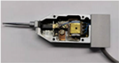 | 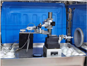 |
| LDC-based sensor | 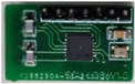 |  | 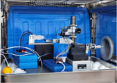 |
Publisher’s Note: MDPI stays neutral with regard to jurisdictional claims in published maps and institutional affiliations. |
© 2022 by the authors. Licensee MDPI, Basel, Switzerland. This article is an open access article distributed under the terms and conditions of the Creative Commons Attribution (CC BY) license (https://creativecommons.org/licenses/by/4.0/).
Share and Cite
Lu, X.; Tian, G.; Wang, Z.; Li, W.; Yang, D.; Li, H.; Wang, Y.; Ni, J.; Zhang, Y. Research on the Time Drift Stability of Differential Inductive Displacement Sensors with Frequency Output. Sensors 2022, 22, 6234. https://doi.org/10.3390/s22166234
Lu X, Tian G, Wang Z, Li W, Yang D, Li H, Wang Y, Ni J, Zhang Y. Research on the Time Drift Stability of Differential Inductive Displacement Sensors with Frequency Output. Sensors. 2022; 22(16):6234. https://doi.org/10.3390/s22166234
Chicago/Turabian StyleLu, Xiaolong, Guiyun Tian, Zongwen Wang, Wentao Li, Dehua Yang, Haoran Li, You Wang, Jijun Ni, and Yong Zhang. 2022. "Research on the Time Drift Stability of Differential Inductive Displacement Sensors with Frequency Output" Sensors 22, no. 16: 6234. https://doi.org/10.3390/s22166234