
Effects of Weak Bedding Plane, Fault, and Extreme Rainfall on the Landslide Event of a High Cut-Slope

Abstract
:1. Introduction
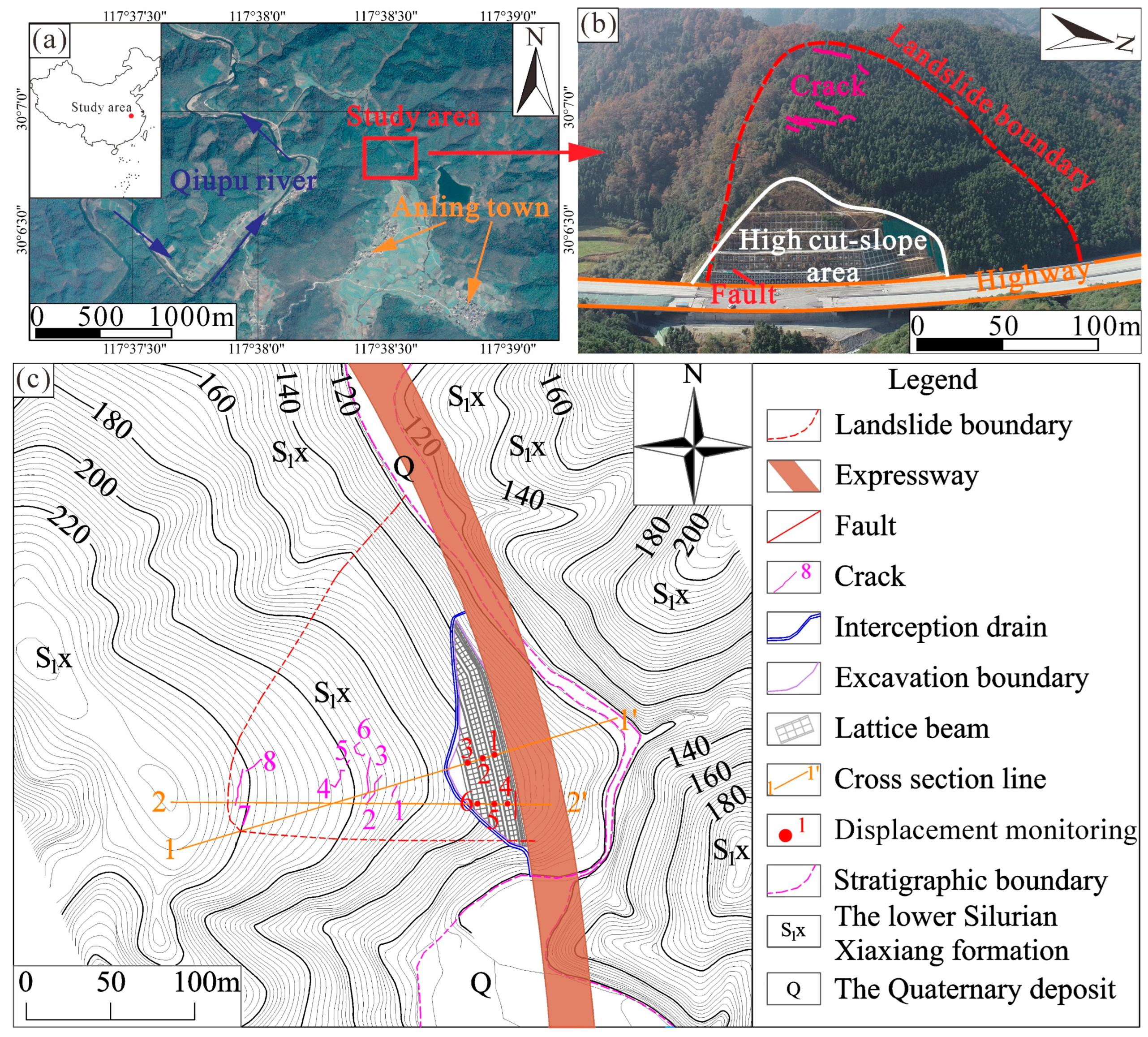
2. Study Area
3. Deformation Characteristics of the Anling Landslide
3.1. Process of the Slope Excavation
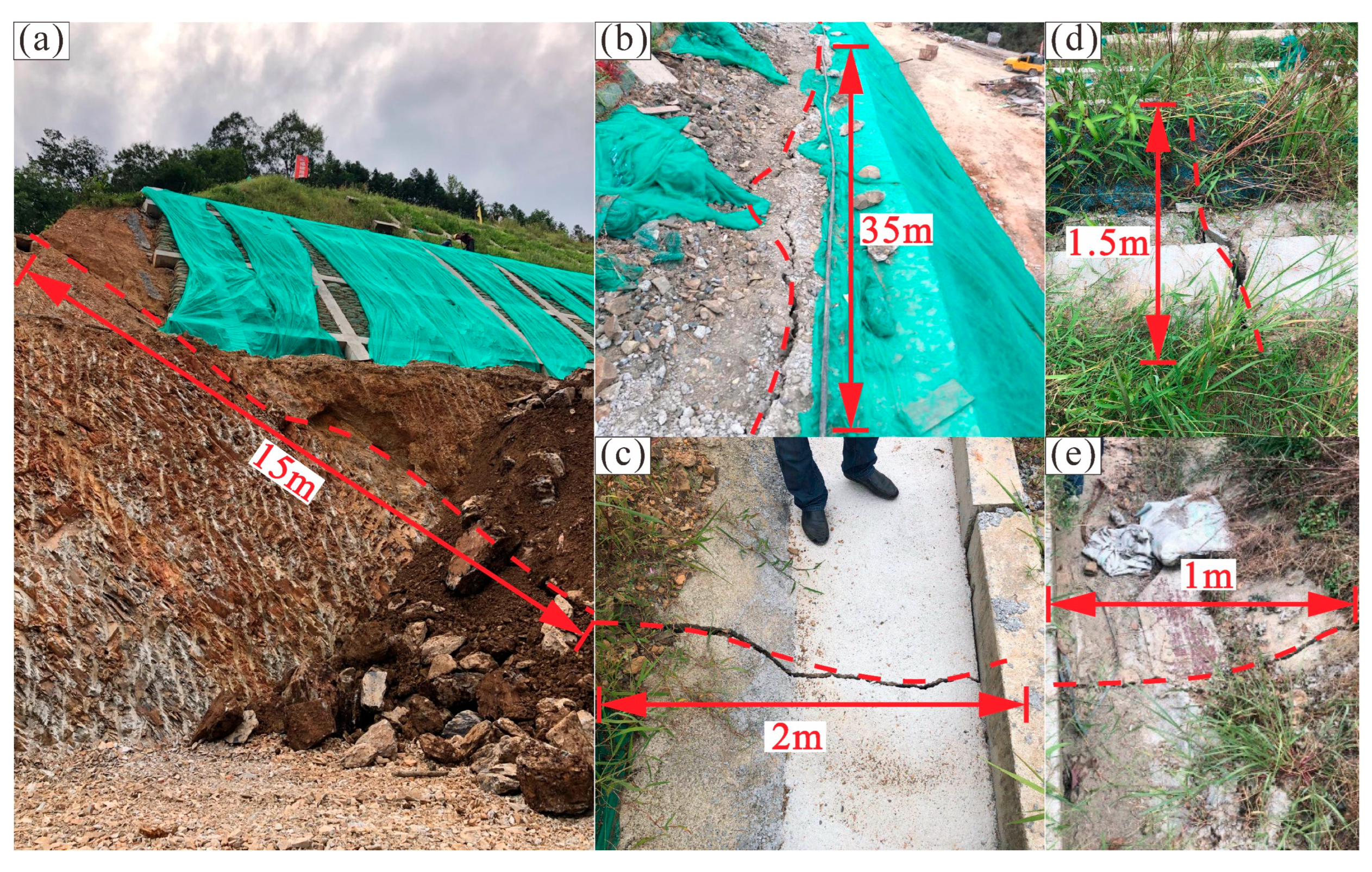
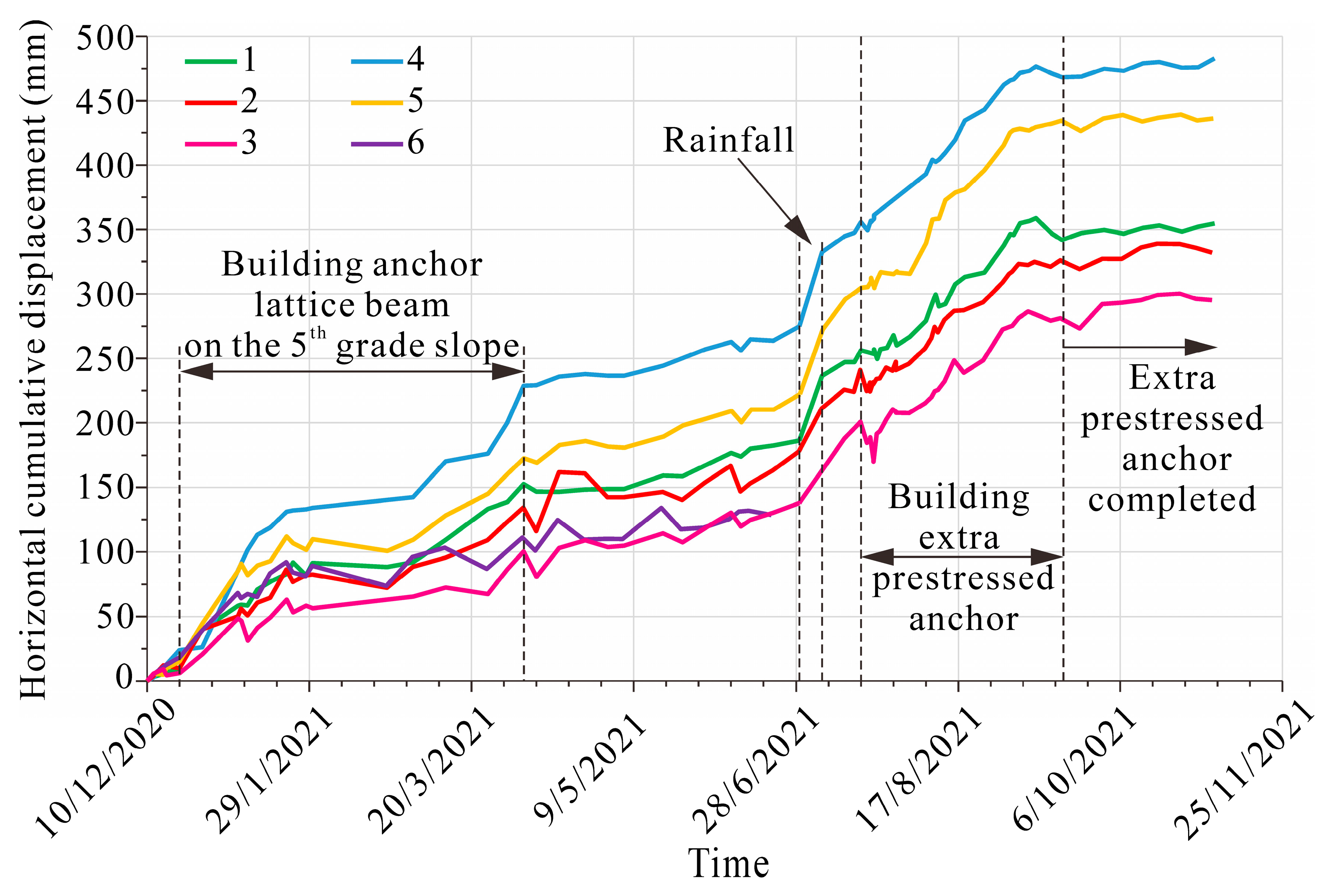
3.2. Deformation Characteristics of the Anling Landslide
4. Numerical Simulation of the Anling Landslide
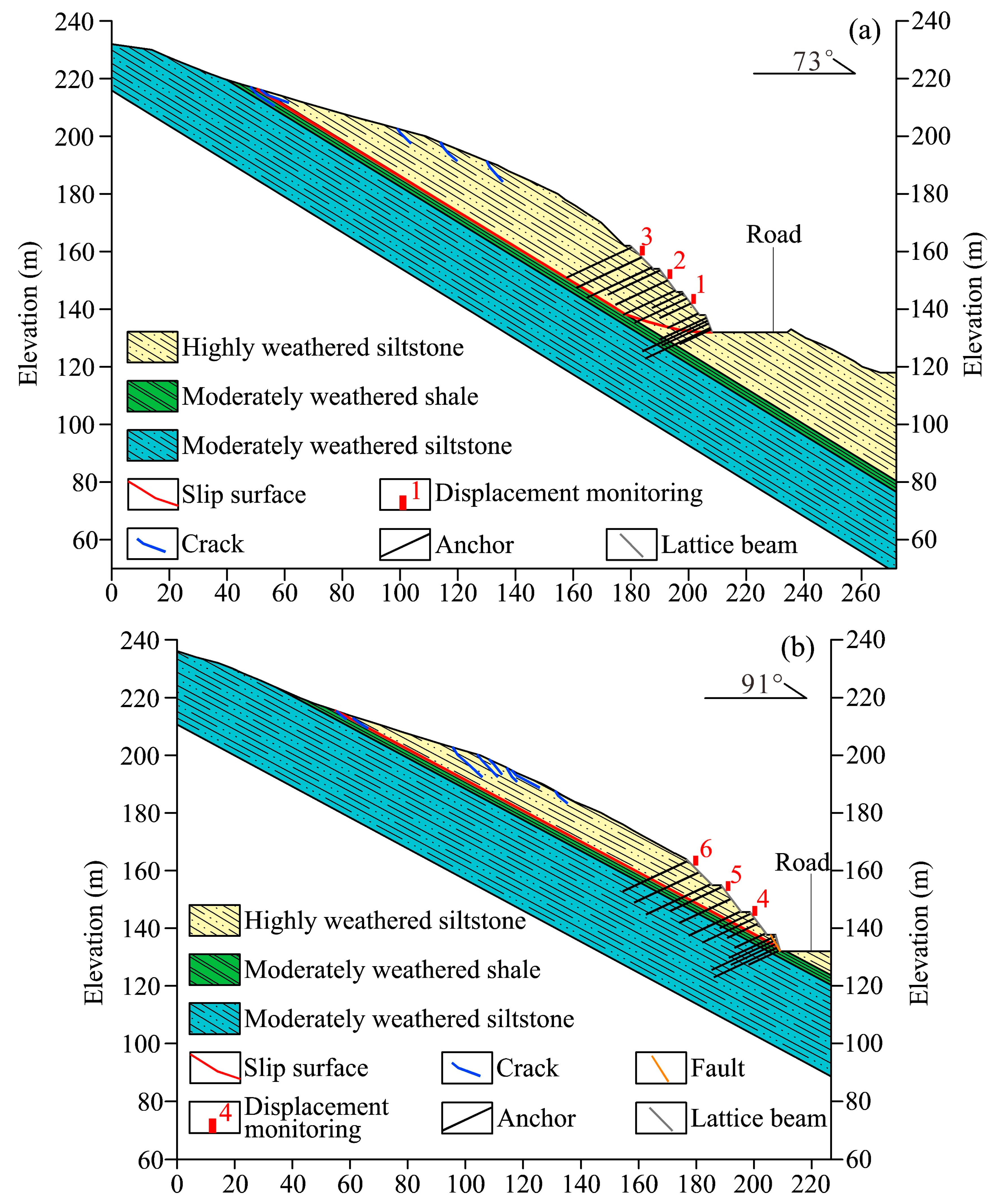
4.1. Numerical Model Descriptions
4.2. Result of Numerical Simulation
4.3. Failure Mechanism of the Anling Landslide
5. Discussion
5.1. Effect of the Fault on the Anling Landslide
5.2. Selection of Appropriate Landslide Protection Measures during Construction
6. Conclusions
- The weak bedding plane resulting in a potential slip surface is the inherent geological reason for the landslide, while the hydro-weakening of moderately weathered shale due to extreme rainfall is the main external triggering factor for the landslide. The combined effect of the two main factors induced the landslide process of the high-cut slope.
- The fault causes a decrease in the mechanical properties of the surrounding rock mass, which is conducive to landslide deformation. The process shall facilitate and accelerate the failure of the landslide.
- Arranging and installing one row of piles in the middle of the landslide is a reliable and economical protection measure to prevent the landslide from deformation when the anchors have been embedded in the toe of the landslide.
Author Contributions
Funding
Institutional Review Board Statement
Informed Consent Statement
Data Availability Statement
Conflicts of Interest
References
- Feng, X.T.; Zhou, Y.Y.; Jiang, Q. Rock mechanics contributions to recent hydroelectric developments in China. J. Rock Mech. Geotech. Eng. 2019, 11, 511–526. [Google Scholar] [CrossRef]
- Chehlafi, A.; Kchikach, A.; Derradji, A.; Mequedade, N. Highway cutting slopes with high rainfall erosion in Morocco: Evaluation of soil losses and erosion control using concrete arches. Eng. Geol. 2019, 260, 105200. [Google Scholar] [CrossRef]
- Kaya, A.; Alemdag, S.; Dag, S.; Gurocak, Z. Stability assessment of high-steep cut slope debris on a landslide (Gumushane, NE Turkey). Bull. Eng. Geol. Environ. 2016, 75, 89–99. [Google Scholar] [CrossRef]
- Postill, H.; Helm, P.R.; Dixon, N.; Glendinning, S.; Smethurst, J.A.; Rouainia, M.; Briggs, K.M.; El-Hamalawi, A.; Blake, A.P. Forecasting the long-term deterioration of a cut slope in high-plasticity clay using a numerical model. Eng. Geol. 2021, 280, 105912. [Google Scholar] [CrossRef]
- Xue, D.; Li, T.; Zhang, S.; Ma, C.; Gao, M.; Liu, J. Failure mechanism and stabilization of a basalt rock slide with weak layers. Eng. Geol. 2018, 233, 213–224. [Google Scholar] [CrossRef]
- Zhang, C.; Su, L.; Chen, W.; Jiang, G. Full-scale performance testing of bored piles with retaining walls in high cutting slope. Transp. Geotech. 2021, 29, 100563. [Google Scholar] [CrossRef]
- Huang, L.; Zeng, X.; Fu, J.; Han, Y.; Chen, H. Safety risk assessment using a BP neural network of high cutting slope construction in high-speed railway. Buildings 2022, 12, 598. [Google Scholar] [CrossRef]
- Dou, H.; Huang, S.; Wang, H.; Jian, W. Repeated failure of a high cutting slope induced by excavation and rainfall: A case study in Fujian, Southeast China. Bull. Eng. Geol. Environ. 2022, 81, 227. [Google Scholar] [CrossRef]
- Li, Q.; Wang, Y.M.; Zhang, K.B.; Yu, H.; Tao, Z.Y. Field investigation and numerical study of a siltstone slope instability induced by excavation and rainfall. Landslides 2020, 17, 1485–1499. [Google Scholar] [CrossRef]
- Sun, D.; Shi, S.; Wen, H.; Xu, J.; Zhou, X.; Wu, J. A hybrid optimization method of factor screening predicated on GeoDetector and Random Forest for Landslide Susceptibility Mapping. Geomorphology 2021, 379, 107623. [Google Scholar] [CrossRef]
- Yin, Y.; Sun, P.; Zhang, M.; Li, B. Mechanism on apparent dip sliding of oblique inclined bedding rockslide at Jiweishan, Chongqing, China. Landslides 2011, 8, 49–65. [Google Scholar] [CrossRef]
- Zhao, L.; Li, D.; Tan, H.; Cheng, X.; Zuo, S. Characteristics of failure area and failure mechanism of a bedding rockslide in Libo County, Guizhou, China. Landslides 2019, 16, 1367–1374. [Google Scholar] [CrossRef]
- Li, L.Q.; Ju, N.P. Effect of the inclined weak interlayers on the rainfall response of a bedded rock slope. J. Mt. Sci. 2016, 13, 1663–1674. [Google Scholar] [CrossRef]
- Rong, P.; Zou, Y.; Lin, J.; Chen, Q.; Zheng, L.; Jin, K. Study of mechanical properties and failure characteristics of combined rock mass with weak interlayer. Geomech. Geophys. Geo-Energy Geo-Resour. 2022, 8, 89. [Google Scholar] [CrossRef]
- Stead, D. The Influence of Shales on Slope Instability. Rock Mech. Rock Eng. 2016, 49, 635–651. [Google Scholar] [CrossRef]
- Wang, J.J.; Zhao, T.L.; Chai, H.J.; Tang, S.C. Failure of a rock slope 16.5 years after excavation in repeated strata of sandstone and mudstone. Environ. Earth Sci. 2016, 75, 1458. [Google Scholar] [CrossRef]
- Sun, C.; Ling, S.; Wu, X.; Li, X.; Chen, J.; Jiang, W. Oxidation of black shale and its deterioration mechanism in the slip zone of the Xujiaping landslide in Sichuan Province, Southwestern China. Catena 2021, 200, 105139. [Google Scholar] [CrossRef]
- Raghuvanshi, T.K. Plane failure in rock slopes—A review on stability analysis techniques. J. King Saud Univ.-Sci. 2019, 31, 101–109. [Google Scholar] [CrossRef]
- Arai, N.; Chigira, M. Distribution of gravitational slope deformation and deep-seated landslides controlled by thrust faults in the Shimanto accretionary complex. Eng. Geol. 2019, 260, 105236. [Google Scholar] [CrossRef]
- Stead, D.; Wolter, A. A critical review of rock slope failure mechanisms: The importance of structural geology. J. Struct. Geol. 2015, 74, 1–23. [Google Scholar] [CrossRef]
- Vick, L.M.; Bohme, M.; Rouyet, L.; Bergh, S.G.; Corner, G.D.; Lauknes, T.R. Structurally controlled rock slope deformation in northern Norway. Landslides 2020, 17, 1745–1776. [Google Scholar] [CrossRef]
- Ehteshami-Moinabadi, M. Properties of fault zones and their influences on rainfall-induced landslides, examples from Alborz and Zagros ranges. Environ. Earth Sci. 2022, 81, 168. [Google Scholar] [CrossRef]
- Miao, F.; Wu, Y.; Torok, A.; Li, L.; Xue, Y. Centrifugal model test on a riverine landslide in the Three Gorges Reservoir induced by rainfall and water level fluctuation. Geosci. Front. 2022, 13, 101378. [Google Scholar] [CrossRef]
- Yeh, P.T.; Lee, K.Z.Z.; Chang, K.T. 3D Effects of permeability and strength anisotropy on the stability of weakly cemented rock slopes subjected to rainfall infiltration. Eng. Geol. 2020, 266, 105459. [Google Scholar] [CrossRef]
- Zhang, Q.; Wang, L.; Zhang, H. Rainfall infiltration process of a rock slope with considering the heterogeneity of saturated hydraulic conductivity. Front. Earth Sci. 2022, 9, 804005. [Google Scholar] [CrossRef]
- Li, D.; Yin, K.; Leo, C. Analysis of Baishuihe landslide influenced by the effects of reservoir water and rainfall. Environ. Earth Sci. 2010, 60, 677–687. [Google Scholar] [CrossRef]
- Xu, Y.; Li, J.; Fan, H.; Chen, L.; Zhao, Y.; Li, L. Stability Analysis of Clastic Rock Slope with Mudstone Interlayer Under Rainfall Infiltration. Geotech. Geol. Eng. 2017, 35, 1871–1883. [Google Scholar] [CrossRef]
- Liu, X.; Xu, M. The unsaturated hydromechanical coupling model of rock slope considering rainfall infiltration using DDA. Geofluids 2017, 2017, 1513421. [Google Scholar] [CrossRef]
- Pan, Y.; Wu, G.; Zhao, Z.; He, L. Analysis of rock slope stability under rainfall conditions considering the water-induced weakening of rock. Comput. Geotech. 2020, 128, 103806. [Google Scholar] [CrossRef]
- Li, D.Y.; Sun, Y.Q.; Yin, K.L.; Miao, F.S.; Glade, T.; Leo, C. Displacement characteristics and prediction of Baishuihe landslide in the Three Gorges Reservoir. J. Mt. Sci. 2019, 16, 2203–2214. [Google Scholar] [CrossRef]
- Peruccacci, S.; Brunetti, M.T.; Gariano, S.L.; Melillo, M.; Rossi, M.; Guzzetti, F. Rainfall thresholds for possible landslide occurrence in Italy. Geomorphology 2017, 290, 39–57. [Google Scholar] [CrossRef]
- Marc, O.; Gosset, M.; Saito, H.; Uchida, T.; Malet, J.P. Spatial Patterns of Storm-Induced Landslides and Their Relation to Rainfall Anomaly Maps. Geophys. Res. Lett. 2019, 46, 11167–11177. [Google Scholar] [CrossRef]
- Chen, H.; Zhang, G.; Chang, Z.; Wen, L.; Gao, W. Failure Analysis of a Highway Cut Slope with Anti-Slide Piles. Geofluids 2021, 2021, 6622214. [Google Scholar] [CrossRef]
- Yang, H.; White, D.J.; Schaefer, V.R. In-situ Borehole Shear Test and Rock Borehole Shear Test for Slope Investigation. In Proceedings of the GeoShanghai International Conference 2006, Shanghai, China, 6–8 June 2006; pp. 293–298. [Google Scholar] [CrossRef]
- Beavis, F.C.; Roberts, F.I.; Minskaya, L. Engineering aspects of weathering of low grade metapelites in an arid climatic zone. Q. J. Eng. Geol. 1982, 15, 29–45. [Google Scholar] [CrossRef]
- Li, B.; Huang, D. Complex Failure Simulation of Underinclined Shale Slope Based on Discrete Element Method. Earth Sci. Res. J. 2020, 24, 83–89. [Google Scholar] [CrossRef]
- Hou, Z.; Gutierrez, M.; Wang, A.; Almrabat, A.; Yang, C. Mechanical properties and brittleness of shale with different degrees of fracturing-fluid saturation. Curr. Sci. 2018, 115, 1163–1173. [Google Scholar] [CrossRef]
- Bian, K.; Liu, J.; Zhang, W.; Zheng, X.; Ni, S.; Liu, Z. Mechanical Behavior and Damage Constitutive Model of Rock Subjected to Water-Weakening Effect and Uniaxial Loading. Rock Mech. Rock Eng. 2019, 52, 97–106. [Google Scholar] [CrossRef]
- Ali, F.; Farooq, K.; Mujtaba, H.; Riaz, A.; Ulhaq, E. Influence of Saturation on Rainfall Generated Landslides in Shale along Murree-Kohala Road, Pakistan. J. Geol. Soc. India 2016, 88, 718–724. [Google Scholar] [CrossRef]
- Xu, J.; Tang, X.; Wang, Z.; Feng, Y.; Bian, K. Investigating the softening of weak interlayers during landslides using nanoindentation experiments and simulations. Eng. Geol. 2020, 277, 105801. [Google Scholar] [CrossRef]
- Bian, K.; Chen, Y.A.; Liu, J.; Cui, D.S.; Li, Y.R.; Liang, W.D.; Han, X. The unloading failure characteristics of shale under different water absorption time using the PFC numerical method. Rock Soil Mech. 2020, 41, 355–367. [Google Scholar] [CrossRef]
- Agliardi, F.; Crosta, G.B.; Meloni, F.; Valle, C.; Rivolta, C. Structurally-controlled instability, damage and slope failure in a porphyry rock mass. Tectonophysics 2013, 605, 34–47. [Google Scholar] [CrossRef]
- Wang, X.; Crosta, G.B.; Clague, J.J.; Stead, D.; Sun, J.; Qi, S.; Liu, H. Fault controls on spatial variation of fracture density and rock mass strength within the Yarlung Tsangpo Fault damage zone (southeastern Tibet). Eng. Geol. 2021, 291, 106238. [Google Scholar] [CrossRef]
- Bauer, J.F.; Meier, S.; Philipp, S.L. Architecture, fracture system, mechanical properties and permeability structure of a fault zone in Lower Triassic sandstone, Upper Rhine Graben. Tectonophysics 2015, 647, 132–145. [Google Scholar] [CrossRef]
- Yin, Q.; Jing, H.; Su, H.; Zhao, H. Experimental Study on Mechanical Properties and Anchorage Performances of Rock Mass in the Fault Fracture Zone. Int. J. Geomech. 2018, 18, 04018067. [Google Scholar] [CrossRef]


| Material | Density (kg/m3) | Cohesion (kPa) | Internal Friction Angle (°) | Young’s Modulus (MPa) | Poisson’s Ratio | Permeability Coefficient (cm/s) | Porosity | Initial Force (kN) |
|---|---|---|---|---|---|---|---|---|
| Highly weathered siltstone | 2150 | 38 | 30 | 5800 | 0.33 | 1.0 × 10⁻⁴ | 0.3 | - |
| Moderately weathered shale | 2250 | 43 | 20 | 2000 | 0.29 | 1.0 × 10⁻⁹ | 0.1 | - |
| Moderately weathered siltstone | 2350 | 40 | 35 | 9100 | 0.19 | 3.0 × 10⁻⁷ | 0.1 | - |
| Weakening moderately weathered shale | 2250 | 20 | 17 | 1500 | 0.29 | 1.0 × 10⁻⁹ | 0.1 | - |
| Highly weathered siltstone in damage zone | 2150 | 30.4 | 24 | 4640 | 0.33 | 1.0 × 10⁻⁴ | 0.3 | - |
| Moderately weathered shale in damage zone | 2250 | 34.4 | 16 | 1600 | 0.29 | 1.0 × 10⁻⁹ | 0.1 | - |
| Moderately weathered siltstone in damage zone | 2350 | 32 | 28 | 7280 | 0.19 | 3.0 × 10⁻⁷ | 0.1 | - |
| Weakening moderately weathered shale in damage zone | 2250 | 16 | 13.6 | 1200 | 0.29 | 1.0 × 10⁻⁹ | 0.1 | - |
| Non-prestressed anchor | - | - | - | 200,000 | - | - | - | - |
| Prestressed anchor | - | - | - | 195,000 | - | - | - | 400 |
| Lattice beam | - | - | - | 30,000 | 0.25 | - | - | - |
| Pile | - | - | - | 30,000 | 0.25 | - | - | - |
Publisher’s Note: MDPI stays neutral with regard to jurisdictional claims in published maps and institutional affiliations. |
© 2022 by the authors. Licensee MDPI, Basel, Switzerland. This article is an open access article distributed under the terms and conditions of the Creative Commons Attribution (CC BY) license (https://creativecommons.org/licenses/by/4.0/).
Share and Cite
Sun, Y.; Li, D.; Miao, F.; She, X.; Yang, S.; Xie, X. Effects of Weak Bedding Plane, Fault, and Extreme Rainfall on the Landslide Event of a High Cut-Slope. Sensors 2022, 22, 6790. https://doi.org/10.3390/s22186790
Sun Y, Li D, Miao F, She X, Yang S, Xie X. Effects of Weak Bedding Plane, Fault, and Extreme Rainfall on the Landslide Event of a High Cut-Slope. Sensors. 2022; 22(18):6790. https://doi.org/10.3390/s22186790
Chicago/Turabian StyleSun, Yiqing, Deying Li, Fasheng Miao, Xiangjie She, Shuo Yang, and Xiaoxu Xie. 2022. "Effects of Weak Bedding Plane, Fault, and Extreme Rainfall on the Landslide Event of a High Cut-Slope" Sensors 22, no. 18: 6790. https://doi.org/10.3390/s22186790