A Frequency Reconfigurable MIMO Antenna with Bandstop Filter Decoupling Network for Cognitive Communication
Abstract
:1. Introduction
2. Antenna Configuration and Design Process
- A.
- Single antenna design;
- B.
- MIMO antenna design;
- C.
- Reconfigurable bandstop filter design as a decoupling structure;
- D.
- MIMO antenna with reconfigurable bandstop filter design.
2.1. Single Antenna Design
2.2. MIMO Antenna Design
2.3. Reconfigurable Bandstop Filter Design as Decoupling Structure
2.4. MIMO Antenna with Reconfigurable Bandstop Filter Design
3. Parametric Analysis
4. Results and Discussion
- A.
- Scattering parameters;
- B.
- Gain, efficiency, and radiation patterns;
- C.
- Diversity parameters.
4.1. Scattering Parameters
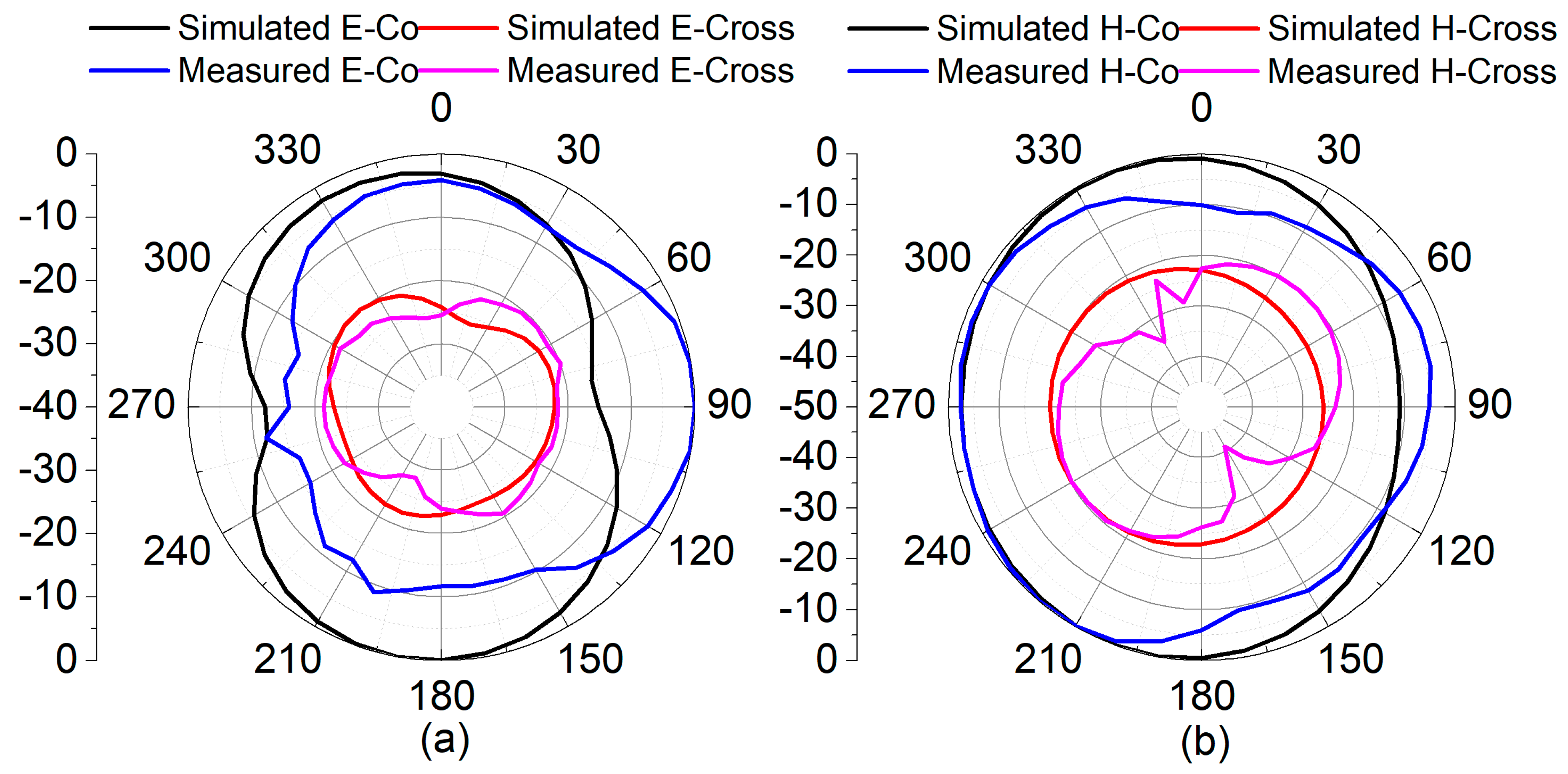
4.2. Gain, Efficiency, and Radiation Patterns
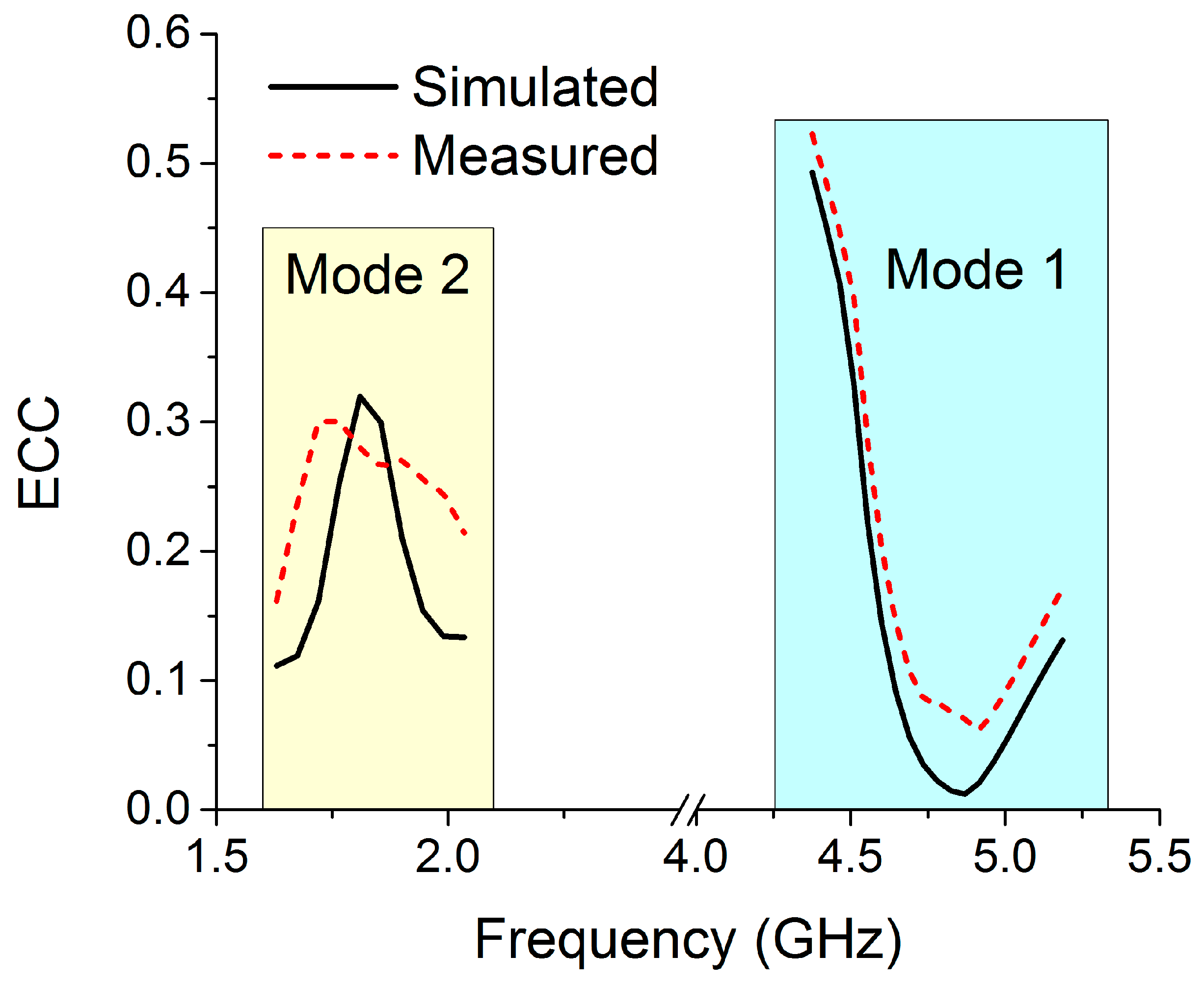
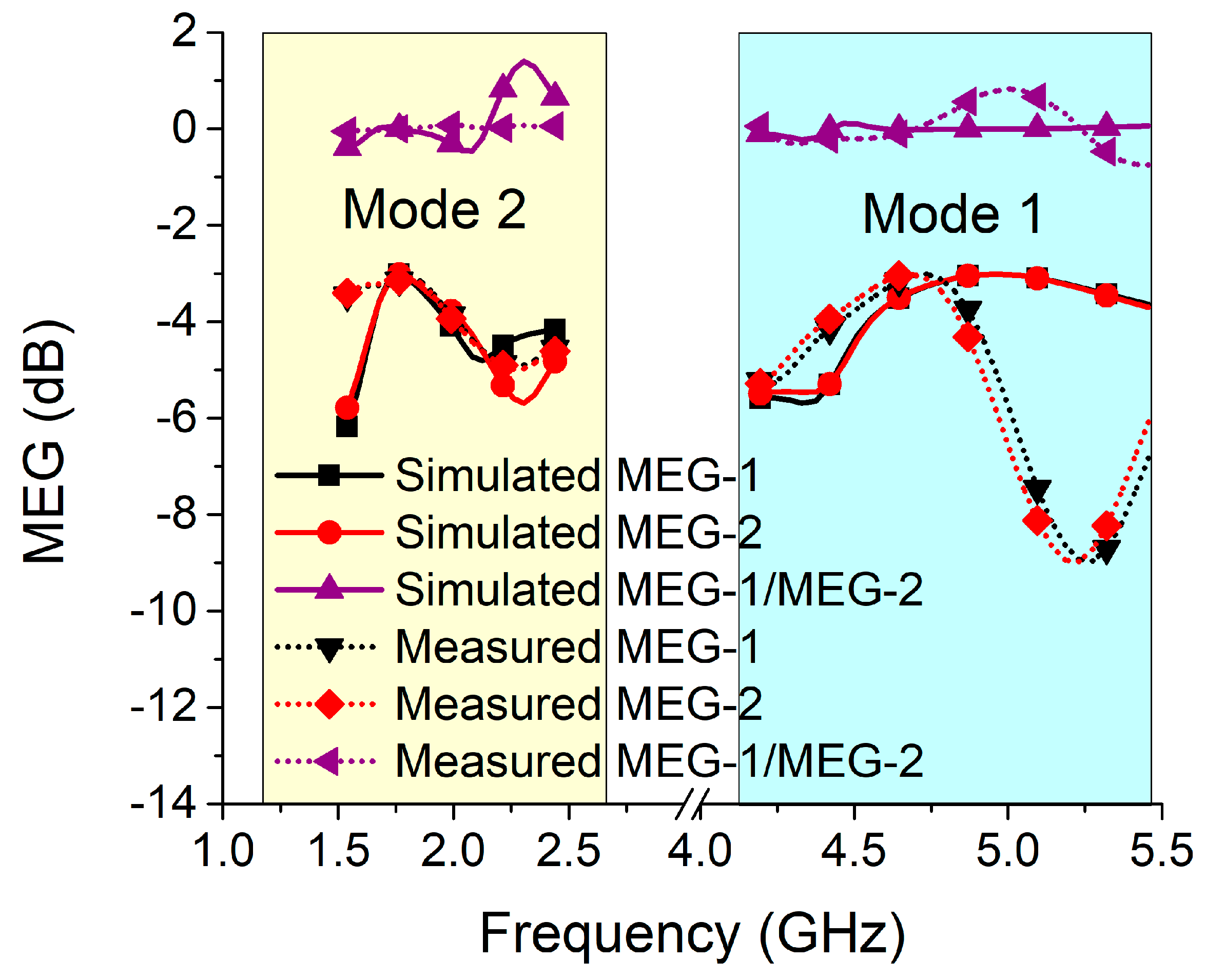
4.3. Diversity Parameters
5. Comparative Analysis
6. Conclusions
Author Contributions
Funding
Informed Consent Statement
Data Availability Statement
Acknowledgments
Conflicts of Interest
References
- Mitola, J. Cognitive radio architecture evolution. Proc. IEEE 2009, 97, 626–641. [Google Scholar] [CrossRef]
- Huang, H.; Li, X.; Liu, Y. A low-profile, dual-polarized patch antenna for 5G MIMO application. IEEE Trans. Antennas Propag. 2018, 67, 1275–1279. [Google Scholar] [CrossRef]
- Li, Q.; Cheung, S.; Zhou, C. A low-profile dual-polarized patch antenna with stable radiation pattern using ground-slot groups and metallic ground wall. IEEE Trans. Antennas Propag. 2017, 65, 5061–5068. [Google Scholar] [CrossRef]
- Li, Z.; Du, Z.; Gong, K. Compact reconfigurable antenna array for adaptive MIMO systems. IEEE Antennas Wirel. Propag. Lett. 2009, 8, 1317–1320. [Google Scholar]
- Sharawi, M.S.; Numan, A.B.; Aloi, D.N. Isolation improvement in a dual-band dual-element MIMO antenna system using capacitively loaded loops. Prog. Electromagn. Res. 2013, 134, 247–266. [Google Scholar] [CrossRef]
- Chen, S.-C.; Wang, Y.-S.; Chung, S.-J. A decoupling technique for increasing the port isolation between two strongly coupled antennas. IEEE Trans. Antennas Propag. 2008, 56, 3650–3658. [Google Scholar] [CrossRef]
- Lee, H.; Lee, B. Compact broadband dual-polarized antenna for indoor MIMO wireless communication systems. IEEE Trans. Antennas Propag. 2015, 64, 766–770. [Google Scholar] [CrossRef]
- Su, S.-W.; Lee, C.-T.; Chang, F.-S. Printed MIMO-antenna system using neutralization-line technique for wireless USB-dongle applications. IEEE Trans. Antennas Propag. 2011, 60, 456–463. [Google Scholar] [CrossRef]
- Alibakhshikenari, M.; Babaeian, F.; Virdee, B.S.; Aïssa, S.; Azpilicueta, L.; See, C.H.; Althuwayb, A.A.; Huynen, I.; Abd-Alhameed, R.A.; Falcone, F.; et al. A comprehensive survey on “Various decoupling mechanisms with focus on metamaterial and metasurface principles applicable to SAR and MIMO antenna systems”. IEEE Access 2020, 8, 192965–193004. [Google Scholar] [CrossRef]
- Bait-Suwailam, M.M.; Boybay, M.S.; Ramahi, O.M. Electromagnetic coupling reduction in high-profile monopole antennas using singlenegative magnetic metamaterials for MIMO applications. IEEE Trans. Antennas Propag. 2010, 58, 2894–2902. [Google Scholar] [CrossRef]
- Luo, C.-M.; Hong, J.-S.; Zhong, L.-L. Isolation enhancement of a very compact UWB-MIMO slot antenna with two defected ground structures. IEEE Antennas Wirel. Propag. Lett. 2015, 14, 1766–1769. [Google Scholar] [CrossRef]
- Islam, H.; Das, S.; Ali, T.; Kumar, P.; Dhar, S.; Bose, T. Split ring resonator-based bandstop filter for improving isolation in compact mimo antenna. Sensors 2021, 21, 2256. [Google Scholar] [CrossRef]
- Palsokar, A.A.; Lahudkar, S. Frequency and pattern reconfigurable rectangular patch antenna using single PIN diode. AEU-Int. J. Electron. Commun. 2020, 125, 153370. [Google Scholar] [CrossRef]
- Parchin, N.O.; Basherlou, H.J.; Al-Yasir, Y.I.; AbdAlhameed, R.A.; Abdulkhaleq, A.M.; Noras, J.M. Recent developments of reconfigurable antennas for current and future wireless communication systems. Electronics 2019, 8, 128. [Google Scholar]
- Lim, J.-H.; Jin, Z.-J.; Song, C.-W.; Yun, T.-Y. Simultaneous frequency and isolation reconfigurable MIMO PIFA using PIN diodes. IEEE Trans. Antennas Propag. 2012, 60, 5939–5946. [Google Scholar] [CrossRef]
- Jin, Z.-J.; Lim, J.-H.; Yun, T.-Y. Frequency reconfigurable multipleinput multiple-output antenna with high isolation. IET Microw. Antennas Propag. 2012, 6, 1095–1101. [Google Scholar] [CrossRef]
- Quddus, A.; Saleem, R.; Shafique, M.F. Compact Electronically Reconfigurable WiMAX Band-Notched Ultra-wideband MIMO Antenna. Radioengineering 2018, 27, 998–1005. [Google Scholar] [CrossRef]
- Pandit, S.; Mohan, A.; Ray, P. Compact frequency-reconfigurable MIMO antenna for microwave sensing applications in WLAN and WiMAX frequency bands. IEEE Sens. Lett. 2018, 2, 3500804. [Google Scholar] [CrossRef]
- Bharathi, A.; Gosula, R.S.R. A novel compact multiband reconfigurable WLAN MIMO antenna. IETE J. Res. 2021, 1–9. [Google Scholar] [CrossRef]
- Islam, H.; Das, S.; Ali, T.; Bose, T.; Kumari, S.; Prakash, O.; Kumar, P. Bandstop Filter Decoupling Technique for Miniaturized Reconfigurable MIMO Antenna. IEEE Access 2022, 10, 19060–19071. [Google Scholar] [CrossRef]
- Yadav, A.; Tewari, M.; Yadav, R.P. Pixel shape ground inspired frequency reconfigurable antenna. Prog. Electromagn. Res. C 2019, 89, 75–85. [Google Scholar] [CrossRef]
- Rodrigo, D.; Jofre, L. Frequency and radiation pattern reconfigurability of a multi-size pixel antenna. IEEE Trans. Antennas Propag. 2012, 60, 2219–2225. [Google Scholar] [CrossRef]
- Hong, J.S.G.; Lancaster, M.J. Microstrip Filters for RF/Microwave Applications; John Wiley & Sons: Hoboken, NJ, USA, 2004. [Google Scholar]
- Blanch, S.; Romeu, J.; Corbella, I. Exact representation of antenna system diversity performance from input parameter description. Electron. Lett. 2003, 39, 705–707. [Google Scholar] [CrossRef]
- Iqbal, A.; Saraereh, O.A.; Ahmad, A.W.; Bashir, S. Mutual coupling reduction using F-shaped stubs in UWB-MIMO antenna. IEEE Access 2017, 6, 2755–2759. [Google Scholar] [CrossRef]
- Sharawi, M.S. Printed MIMO antenna systems: Performance metrics, implementations and challenges. In Forum for Electromagnetic Research Methods and Application Technologies (FERMAT); FERMAT, University of Central Florida: Orlando, FL, USA, 2014; Volume 1, pp. 1–11. [Google Scholar]
- Kumari, T.; Das, G.; Sharma, A.; Gangwar, R.K. Design approach for dual element hybrid MIMO antenna arrangement for wideband applications. Int. J. RF Microw. Comput.-Aided Eng. 2019, 29, e21486. [Google Scholar] [CrossRef]
- Das, G.; Sharma, A.; Gangwar, R.K. Dielectric resonator based circularly polarized MIMO antenna with polarization diversity. Microw. Opt. Technol. Lett. 2018, 60, 685–693. [Google Scholar] [CrossRef]
- Sarkar, G.A.; Ballav, S.; Chatterjee, A.; Ranjit, S.; Parui, S.K. Four element MIMO DRA with high isolation for WLAN applications. Prog. Electromagn. Res. Lett. 2019, 84, 99–106. [Google Scholar] [CrossRef]
- Pant, A.; Singh, M.; Parihar, M.S. A frequency reconfigurable/switchable MIMO antenna for LTE and early 5G applications. AEU-Int. J. Electron. Commun. 2021, 131, 153638. [Google Scholar] [CrossRef]

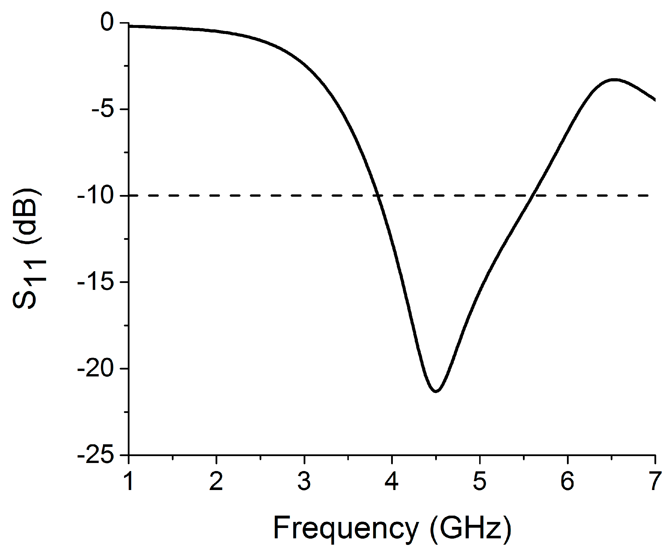
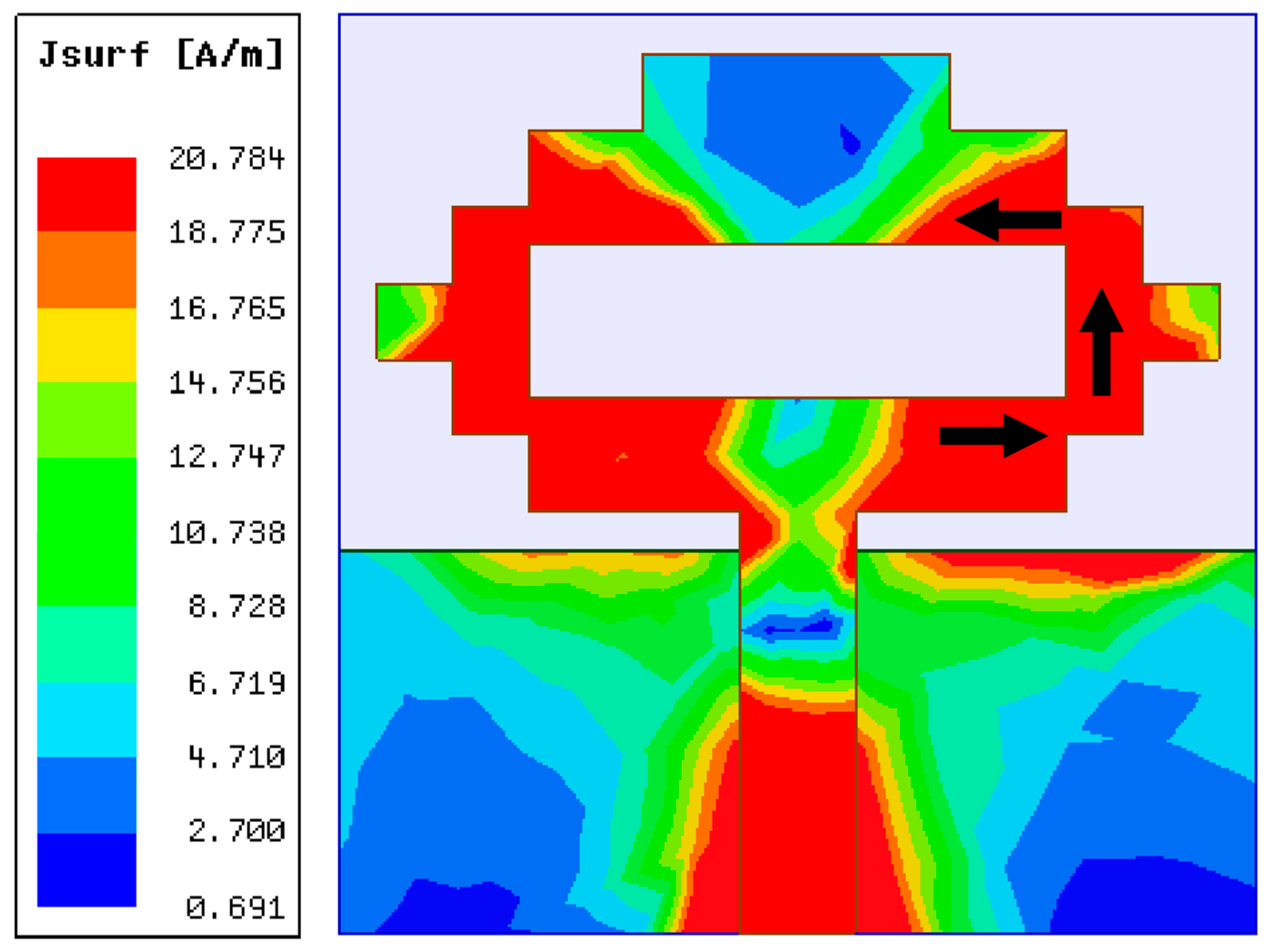
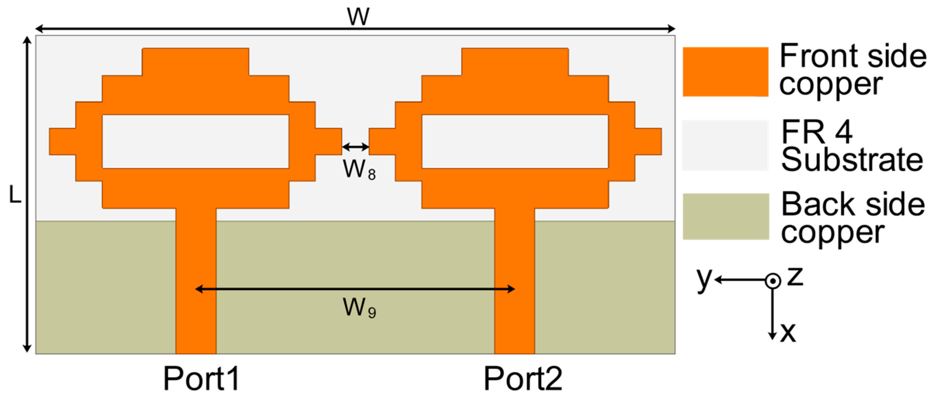
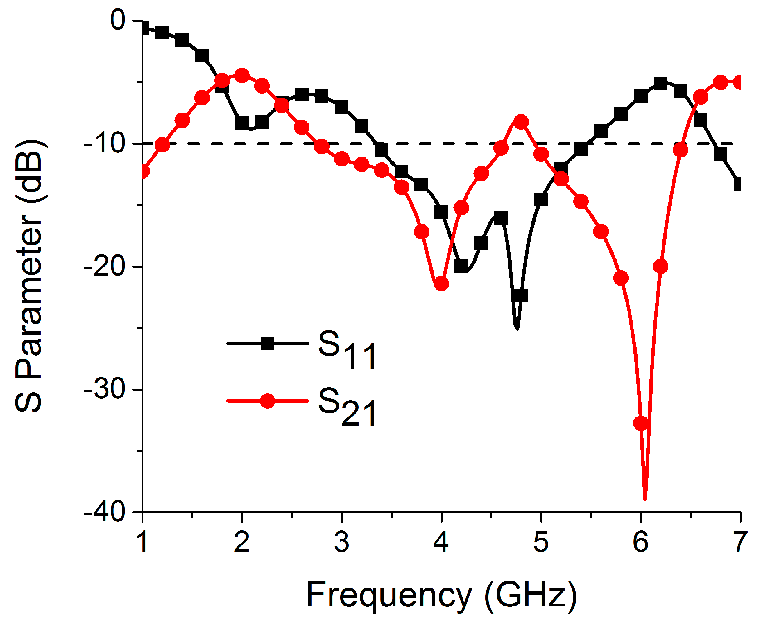
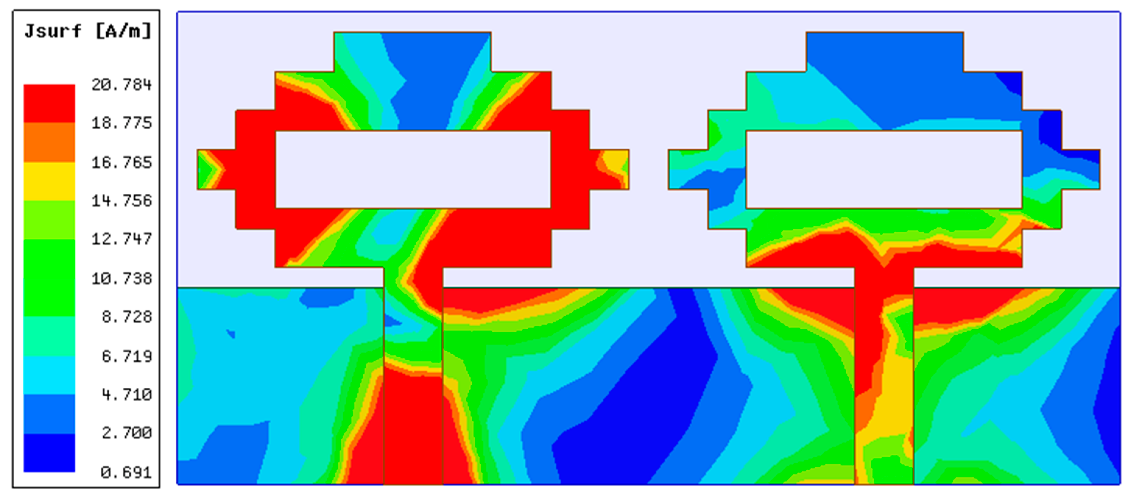
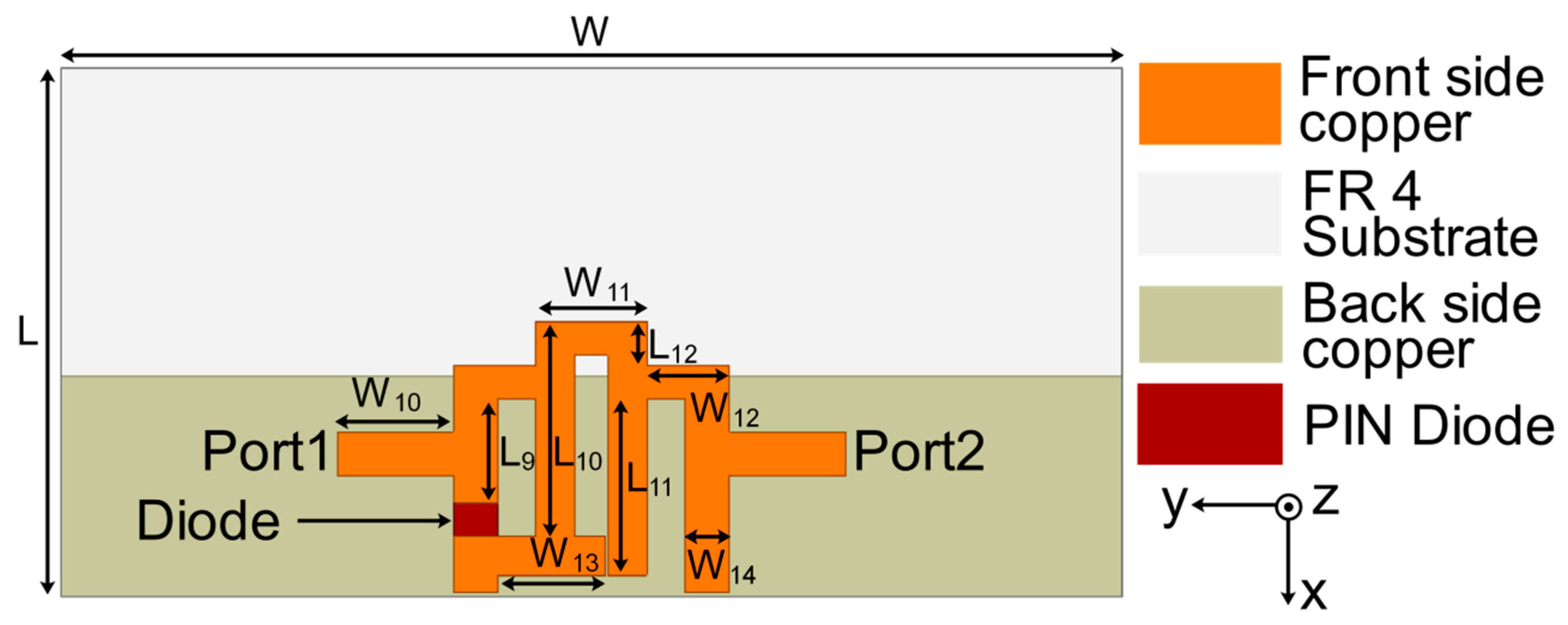
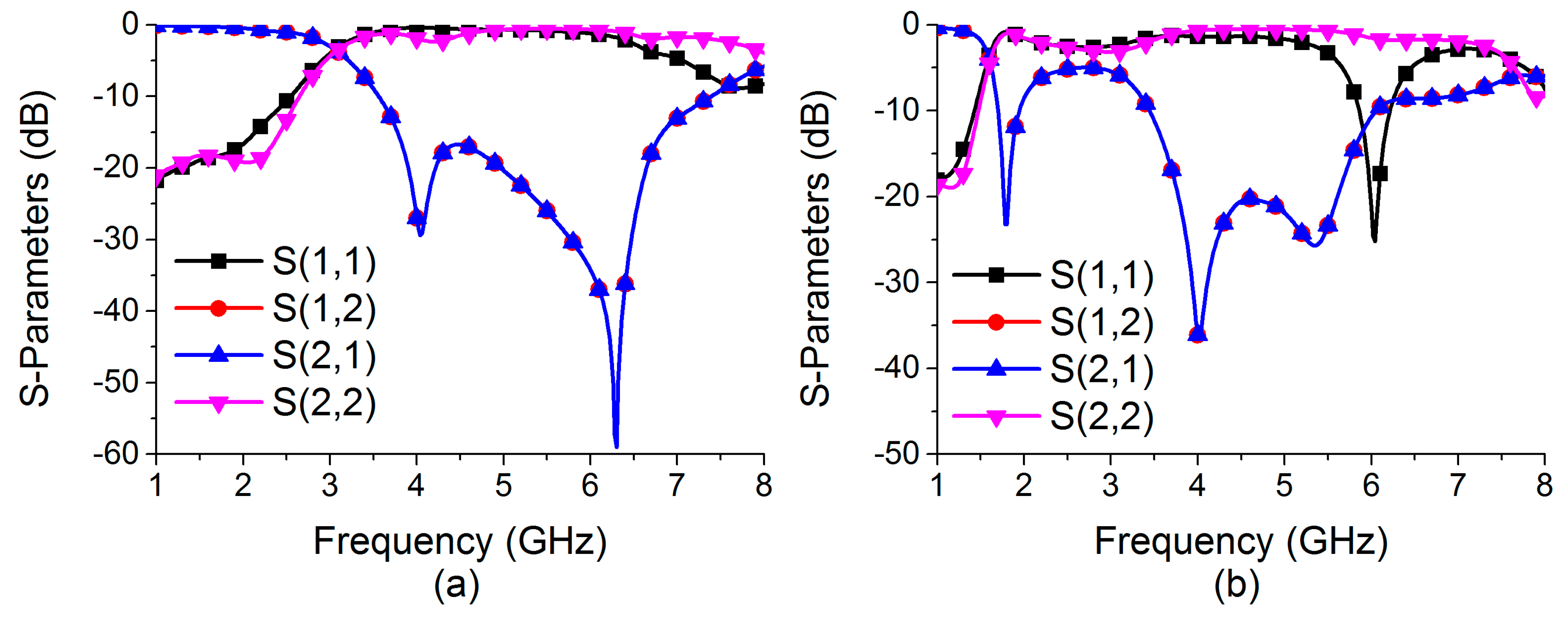
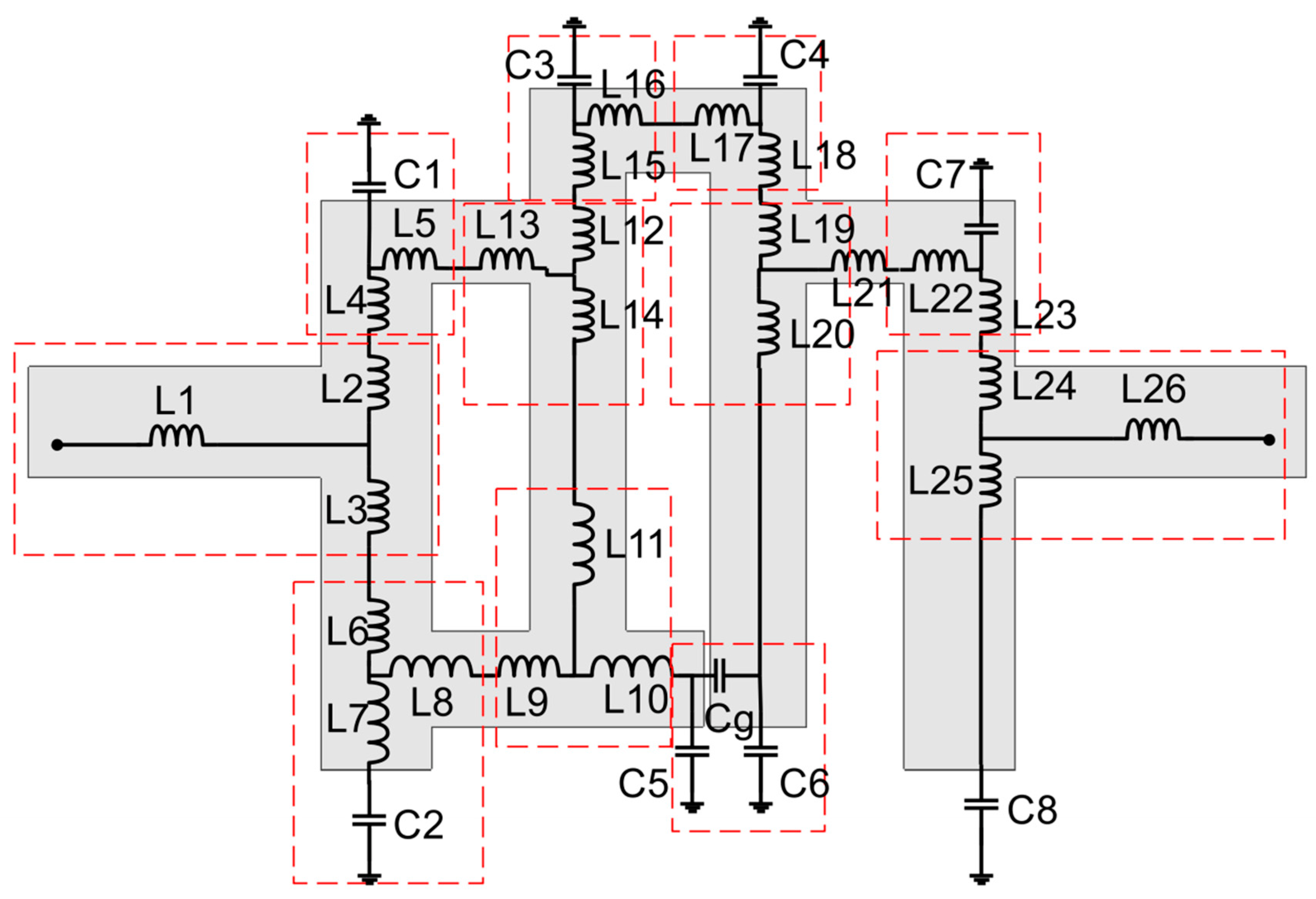




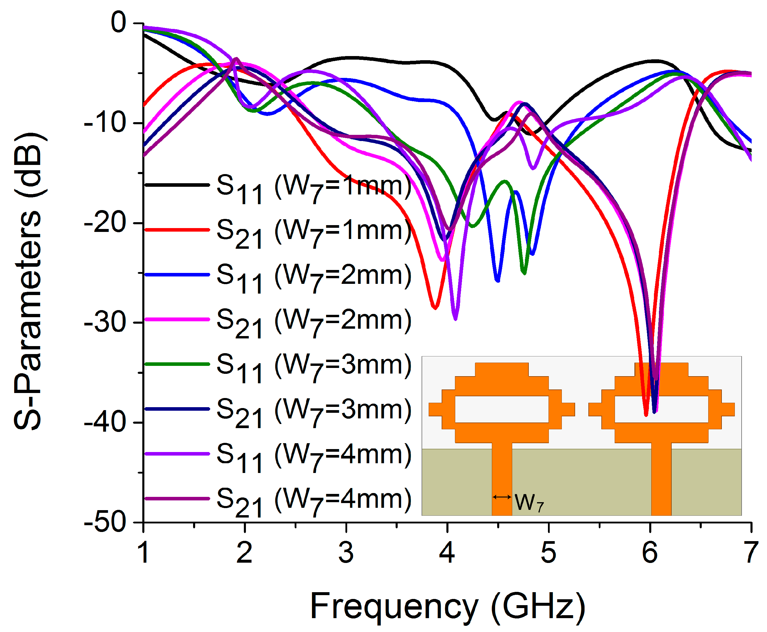
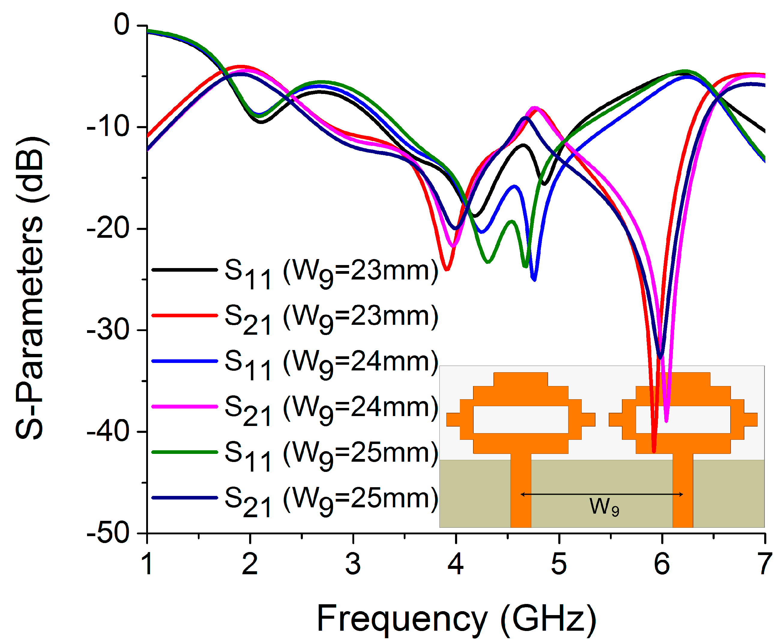
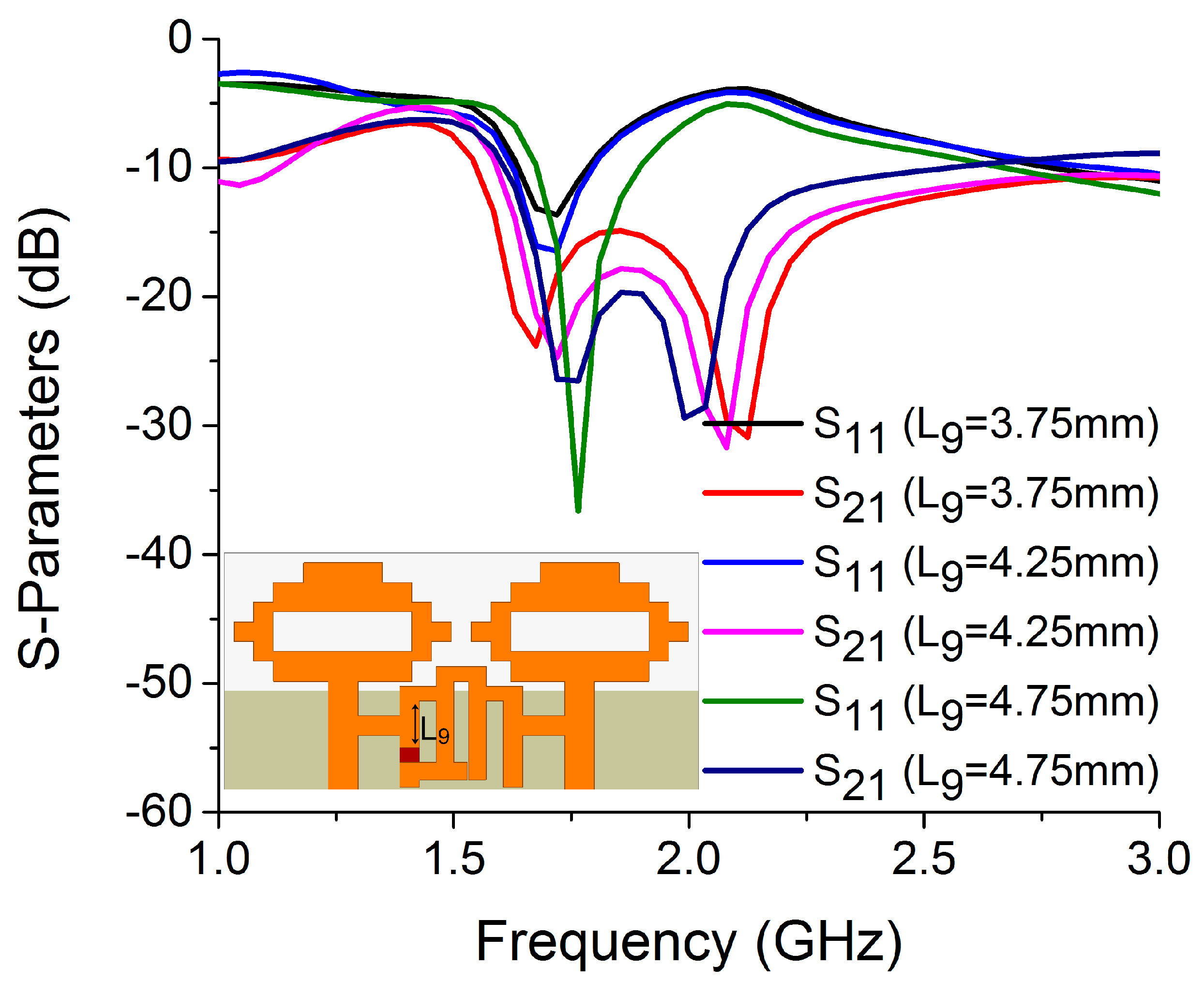
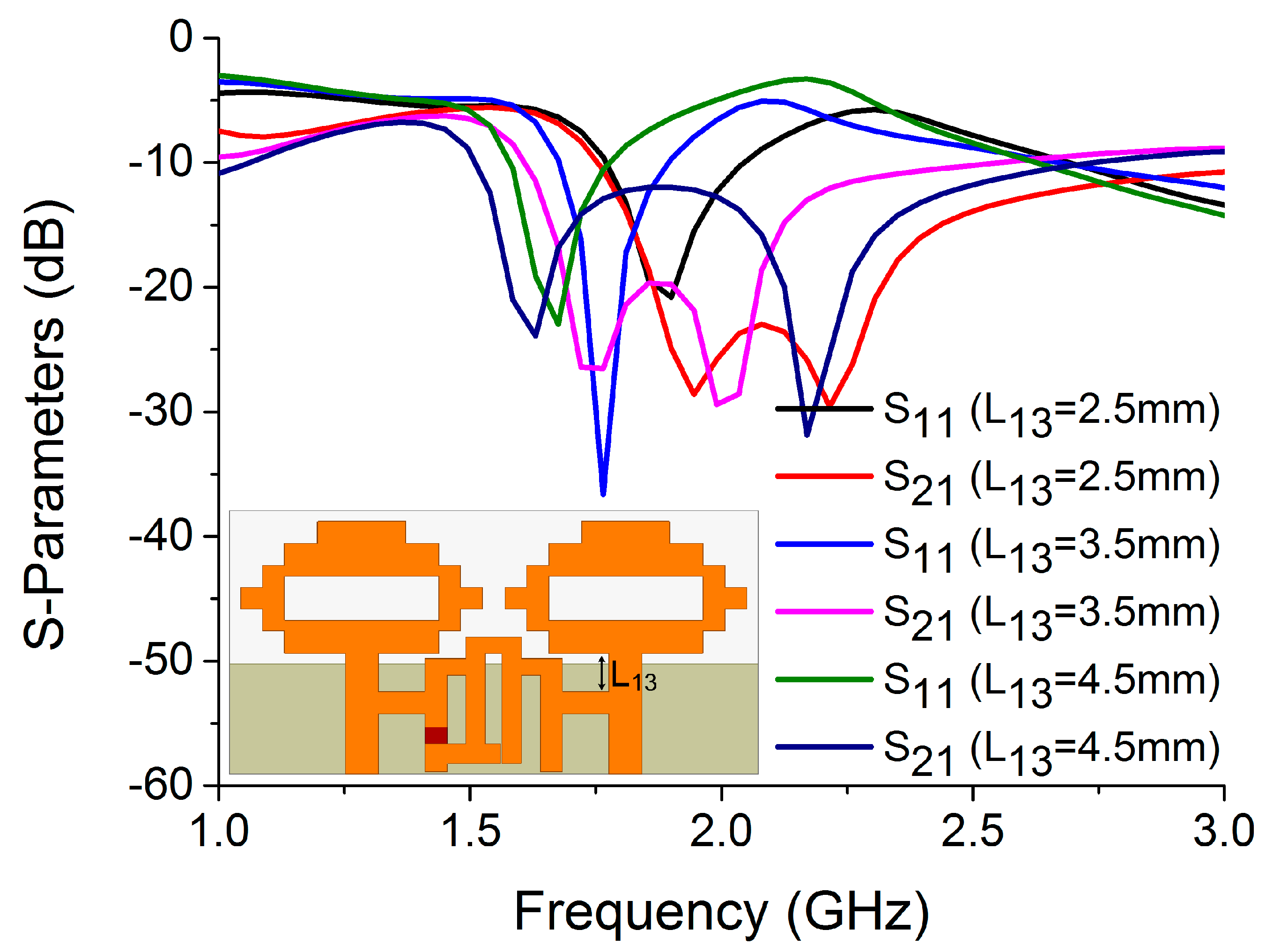




| Filter Metrics | Mode 1 | Mode 2 |
|---|---|---|
| 10 dB Band (S21) | 3.56–7.39 GHz | 1.69–1.93 GHz, 3.44–6.06 GHz |
| Filtering frequency | 4.75 GHz | 1.77 GHz |
| Return loss (S11) | 0.67 dB | 0.86 dB |
| Isolation (S21) | 18.07 dB | 23.27 dB |
| Modes | Inductor (nH) | Capacitor (pF) |
|---|---|---|
| Mode 1 | L1 = 0.1, L2 = 0.09, L3 = 1.86, L4 = 0.51, L5 = 0.1, L6 = 05, L7 = 0.5, L8 = 0.8, L9 = 3.7, L10 = 3.7, L11 = 31, L12 = 0.18, L13 = 0.11, L14 = 9, L15 = 0.5, L16 = 0.8, L17 = 1.2, L18 = 0.01, L19 = 0.01, L20 = 0.57, L21 = 0.15, L22 = 0.15, L23 = 0.35, L24 = 0.27, L25 = 0.92, L26 = 0.1 | C1 = 0.75, C2 = 0.91, C3 = 0.55, C4 = 1.17, C5 = 1.2, C6 = 1.2, Cg = 16.68, C7 = 0.06, C8 = 0.7 |
| Mode 2 | L1 = 0.1, L2 = 0.09, L3 = 2, L4 = 0.51, L5 = 0.44, L6 = 0.4, L7 = 0.8, L8 = 0.37, L9 = 0.17, L10 = 3.3, L11 = 0.18, L12 = 0.18, L13 = 0.11, L14 = 0.57, L15 = 0.8, L16 = 1.2, L17 = 0.01, L18 = 0.01, L19 = 0.57, L20 = 0.15, L21 = 0.15, L22 = 0.86, L23 = 0.01, L24 = 0.01, L25 = 0.1 | C1 = 0.55, C2 = 0.91, C3 = 0.44, C4 = 1.17, C5 = 1.25, C6 = 1.25, Cg = 16.68, C7 = 0.31, C8 = 0.7, C9 = 0.55, C10 = 0.55, Cg1 = 0.31 |
| Ref. | Dimension | No. of Diodes | No. of Ports | Reconfiguration Technique | Isolation Technique | Frequency Reconfigurability Options | Isolation (dB) | Gain (dBi) | ECC | CCL (bits/s/ Hz) |
|---|---|---|---|---|---|---|---|---|---|---|
| [15] | (f = 2.35 GHz) | 4 | 2 | PIN diodes | Band-notched quarter-wave slot line on the ground plane is used between the two reconfigurable antennas. | I. 2.3–2.4 GHz II. 2.5–2.7 GHz III. 3.4–3.6 GHz | 47 43 30.8 | 1.39 1.99 2.78 | 0.1108 0.0788 0.0056 | 10.29 10.61 11.45 (SNR Of 20 dB per port) |
| [16] | (f = 2.4 GHz) | 2 | 2 | PIN diodes | An isolation improvement structure (IIS) is constructed on the ground plane. | I. 2.4–2.483 GHz, 5.15–5.35 GHz II. 3.4–3.6 GHz | 3.81, 1.87 5.15 | <0.02 <0.002 <0.002 | --- | |
| [17] | (f = 3 GHz) | 2 | 2 | PIN diodes | Decoupling structure on the ground plane | I. 3–12 GHz II. 3.2–3.8 GHz | >25 dB | 2.8 −1.1 | <0.001 | <0.5 >0.5 |
| [18] | (f = 2.45 GHz) | 4 | 2 | PIN diodes | T slot and meander line resonator | I. 2.4–2.48 GHz, 3.4–3.6 GHz II. 5.3–5.9 GHz | >25, >28 >26 | 1.06, 1.02 2.46 | <0.08, <0.02 <0.02 | --- |
| [19] | (f = 2.4 GHz) | 2 | 2 | PIN diodes | T slot and meander line resonator | I. 2.4, 5.2 and 5.8 GHz II. 5.2 GHz, 5.8 GH | 20, 20, 20 20, 20 | 2.31, 3.5, 3.7 3.6, 3.75 | --- | --- |
| [20] | (f = 2.5 GHz) | 2 | 2 | PIN diodes | BSF decoupling n/w | I. 3.51–3.79 GHz II. 2.43–2.6 GHz | 42.77 37.49 | 2.92 2.98 | 0.067 0.154 | 0.04812 0.02853 |
| [30] | (f = 2.4 GHz) | 2 | 2 | PIN diodes | Self-isolated | I. 2.0–2.7 GHz II. 3.3–4.02 GHz | 16 19 | 3.7 4.2 | 0.0056 0.0009 | 11.1 10.2 |
| Prop. work | (f = 1.77 GHz) | 1 | 2 | PIN diode | BSF decoupling n/w | I. 4.61–5.53 GHz II. 1.67–1.9 GHz | 42.68 26.52 | 6.63 4.41 | 0.031 0.253 | 0.00144 0.06528 |
Publisher’s Note: MDPI stays neutral with regard to jurisdictional claims in published maps and institutional affiliations. |
© 2022 by the authors. Licensee MDPI, Basel, Switzerland. This article is an open access article distributed under the terms and conditions of the Creative Commons Attribution (CC BY) license (https://creativecommons.org/licenses/by/4.0/).
Share and Cite
Islam, H.; Das, S.; Ali, T.; Bose, T.; Prakash, O.; Kumar, P. A Frequency Reconfigurable MIMO Antenna with Bandstop Filter Decoupling Network for Cognitive Communication. Sensors 2022, 22, 6937. https://doi.org/10.3390/s22186937
Islam H, Das S, Ali T, Bose T, Prakash O, Kumar P. A Frequency Reconfigurable MIMO Antenna with Bandstop Filter Decoupling Network for Cognitive Communication. Sensors. 2022; 22(18):6937. https://doi.org/10.3390/s22186937
Chicago/Turabian StyleIslam, Hashinur, Saumya Das, Tanweer Ali, Tanushree Bose, Om Prakash, and Pradeep Kumar. 2022. "A Frequency Reconfigurable MIMO Antenna with Bandstop Filter Decoupling Network for Cognitive Communication" Sensors 22, no. 18: 6937. https://doi.org/10.3390/s22186937
APA StyleIslam, H., Das, S., Ali, T., Bose, T., Prakash, O., & Kumar, P. (2022). A Frequency Reconfigurable MIMO Antenna with Bandstop Filter Decoupling Network for Cognitive Communication. Sensors, 22(18), 6937. https://doi.org/10.3390/s22186937


